2
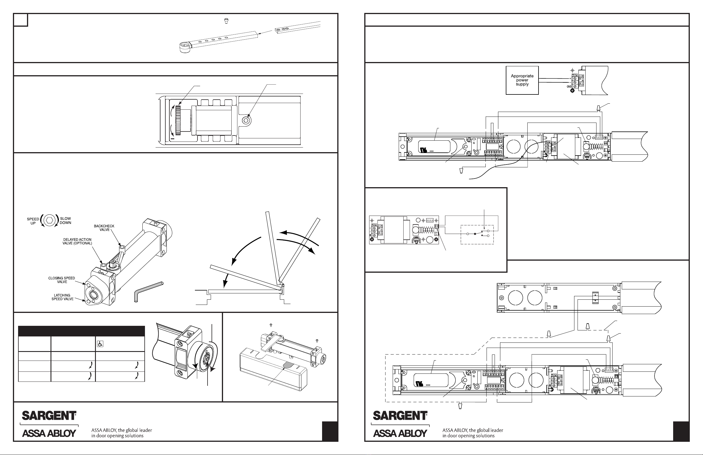
6Adjust hold open angle by adjusting arm length:
Range o 85° to 115° is obtainable.
With roller assembly in hold open setting, open door
and slide insert into main arm or desired hold open.
Secure arms with 9/64" hex screw. Main Arm
Insert
A7694C 3
Final Adjustment and Regulating Procedures
DOOR WIDTH EXTERIOR DOORS I TERIOR DOORS
(I CHES)
30-36 FACTORY SET FACTORY SET
36-42 TUR nut 1-4 TUR nut 1-3
42-48 TUR nut 7-9 TUR nut 4-6
Adjust power to allow door to close and latch.
1/8” HEX SOCKET
WRENCH
BACKCHECK
RANGE
DELAYED ACTION
RANGE
CLOSING SPEED
RANGE
LATCHING SPEED
RANGE
Install cover as shown.
Closing and latching speeds:
Turn valves clockwise to slow down or counterclockwise
to speed up door movement.
Backcheck:
Turn valve clockwise to increase or counterclockwise
to decrease.
CAUTIO : SET VALVE FOR SLIGHT CUSHIO I G
EFFECT. CLOSER CA BE DAMAGED IF THE CHECKI G
ACTIO IS TOO ABRUPT. EVER USE THE BACKCHECK
AS A DOOR STOP. ALWAYS USE A DOOR STOP TO STOP
THE DOOR.
Delayed action feature (optional feature):
When provided, turn valve clockwise to slow down or
counterclockwise to speed up door movement.
Adjusting door to close due to high dra t conditions may exceed ADA
Standards. Consult local ordinances when ire doors are involved.
UMBER OF TUR S OF SPRI G POWER ADJUSTI G UT
Decrease
Increase
Adjusting Nut
5/8" Insert is removable.
Place in unused
opening.
To adjust holding tension:
• Loosen 2.5mm lock down screw.
• Turn knob or desired tension.
• Retighten 2.5mm lock down
screw.
• Install cover plate with 3 screws
as shown in step 4.
Holding tension
adjustment
2.5mm hex lock
down screw
CAUTIO
• Wire stand alone unit to appropriate power supply and ire alarm.
Earth ground wire connects to green wire
• Re er to data sticker or proper input voltage and current speci ications
• Energize power supply. Current draw o .1 AMP per unit
• Open door to hold open point. Door should hold open
• Depress Holder On/O Switch. Door should close and latch
• Depress Holder On/O Switch to reactivate solenoids on both units
• Adjustment o spring power may be necessary to ensure proper latching
1. DISCO ECT ALL POWER BEFORE BEGI I G I STALLATIO
TO PREVE T ELECTRICAL SHOCK A D EQUIPME T DAMAGE.
2. I STALLER MUST BE A TRAI ED, EXPERIE CED
SERVICE PERSO .
3. ALL WIRI G MUST COMPLY WITH APPLICABLE LOCAL
ELECTRICAL CODES, ORDI A CES A D REGULATIO S.
4. MAXIMUM WIRE SIZE IS 18AWG.
12-2468 Unit
Do not use
G D slot of terminal block. Use Green Grounding wire.
9- Companion Unit
Black
Black
Wire nut
12- Smoke
Detector Unit
Yellow
Red
Black
Holder On/Off switch
Smoke detector unit
Red reset switch Yellow Circuit board 120VAC or
24VAC/DC (120VAC shown)
12 11
14 9
73
Field wiring by others
Field wiring by others
• Companion unit is designed to work with
smoke detector unit 12-2468 only.
• Wire companion unit to smoke detector
unit as shown on wiring diagram
• Do not disconnect any existing wires on
smoke detector unit’s terminal strip
• Energize power supply
• Open doors to hold-open point. Doors should hold open
• Depress Holder On/O Switch on circuit board.
Doors should close and latch
• Adjustment o spring power may be
necessary to ensure proper latching
Remove jumper and install
output connector assembly
(Part No. 63-2868) required
for this option
User supplied normally
closed momentary switch
Wiring Optional Remote Push Button
I STALLER: LEAVE I STRUCTIO S WITH BUILDI G OW ER
Hex screw
Wire nut
12- Smoke
Detector Unit
Yellow
Red
Black
Holder On/Off switch
Smoke detector unit
Red reset switch Yellow
Data
sticker
Terminal strip for
power input wiring
Circuit board 120VAC or
24VAC/DC (120VAC shown)
1211
14 9
73
Green grounding wire
Copyright ©2008, Sargent Manufacturing Company, an ASSA ABLOY Group company. All
right re erved. Reproduction in whole or in part without the expre written permi ion of
Sargent Manufacturing Company i prohibited.
A7694C
Copyright ©2008, Sargent Manufacturing Company, an ASSA ABLOY Group company. All
right re erved. Reproduction in whole or in part without the expre written permi ion of
Sargent Manufacturing Company i prohibited.


