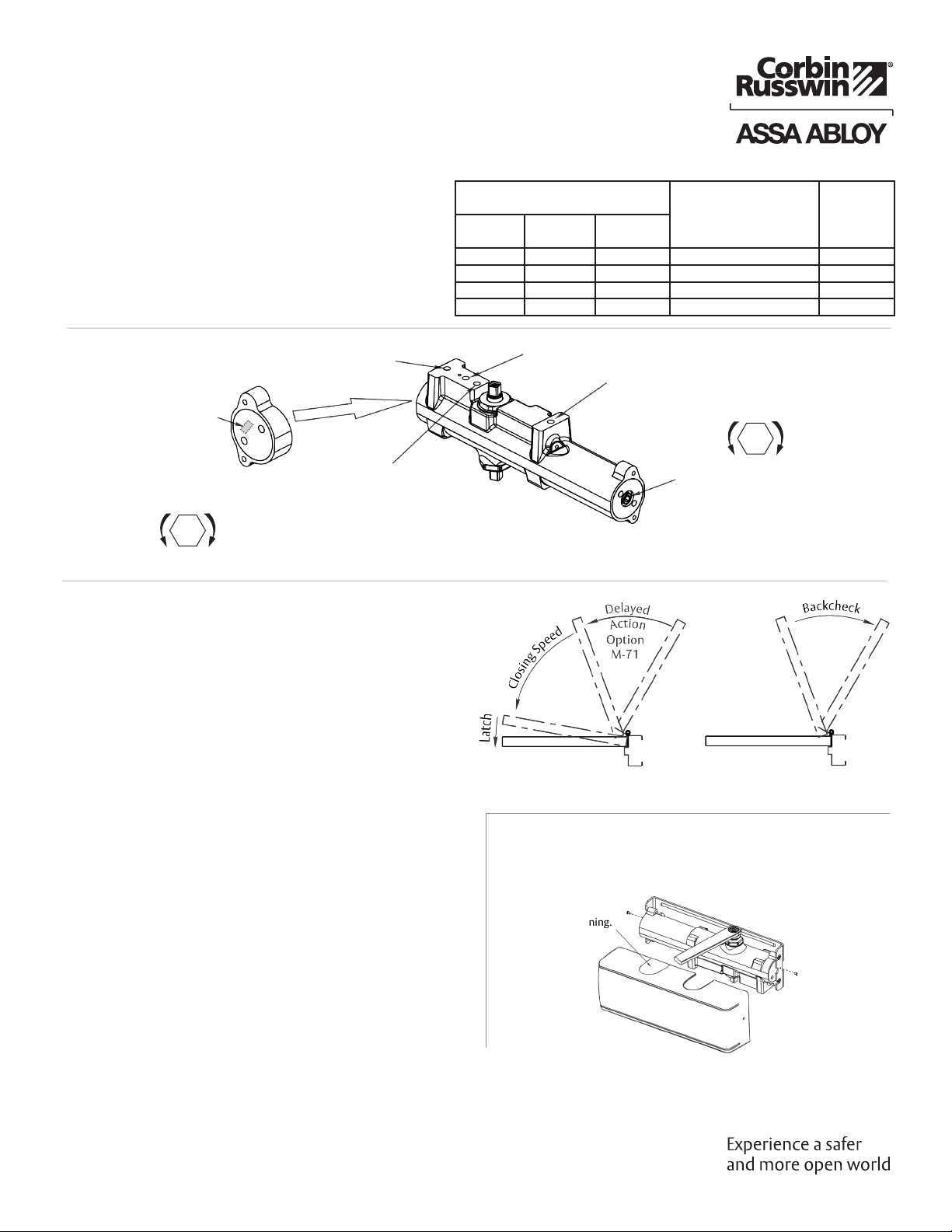
Assa Abloy Corbin Russwin DC8200 Series User manual
Other Assa Abloy Door Opening System manuals

Assa Abloy
Assa Abloy DC135 Service manual

Assa Abloy
Assa Abloy RIXSON W73ER User manual

Assa Abloy
Assa Abloy SARGENT 1331 User manual

Assa Abloy
Assa Abloy DC700G-FMS-K User manual

Assa Abloy
Assa Abloy SARGENT 278 Series User manual

Assa Abloy
Assa Abloy Corbin Russwin DC3210 Series User manual

Assa Abloy
Assa Abloy Corbin Russwin PED4800 Series User manual

Assa Abloy
Assa Abloy NORTON RIXSON 6200 Series User manual
 Series User manual")
Assa Abloy
Assa Abloy Corbin Russwin ED5400 (A) Series User manual

Assa Abloy
Assa Abloy SW200 Manual

Assa Abloy
Assa Abloy SARGENT 1130 Series User manual

Assa Abloy
Assa Abloy Sargent 2409 Series User manual

Assa Abloy
Assa Abloy Corbin Russwin DC8210 Series User manual

Assa Abloy
Assa Abloy Corbin Russwin ED7400 Series User manual

Assa Abloy
Assa Abloy Corbin Russwin PED5000 DB Series User manual

Assa Abloy
Assa Abloy DC200 User manual

Assa Abloy
Assa Abloy besam PUSH-N-GO User manual

Assa Abloy
Assa Abloy DC340DA User manual

Assa Abloy
Assa Abloy G-CO-C User manual

Assa Abloy
Assa Abloy DC3210 Series User manual


Popular Door Opening System manuals by other brands


Stanley
Stanley MA900ñ Installation and owner's manual

WITTUR
WITTUR Hydra Plus UD300 Instruction handbook

Alutech
Alutech TR-3019-230E-ICU Assembly and operation manual

MPC
MPC ATD ACTUATOR 50 ATD-313186 Operating and OPERATING AND INSTALLATION Manual

GEZE
GEZE ECturn user manual

Chamberlain
Chamberlain T user guide