A7974C 9
02/01/13 Copyright © 2009 Sargent Manufacturing Company, an ASSA ABLOY Group company. All rights reserved.
Reproductions in whole or in part without express written permission of Sargent Manufacturing Company is prohibited.
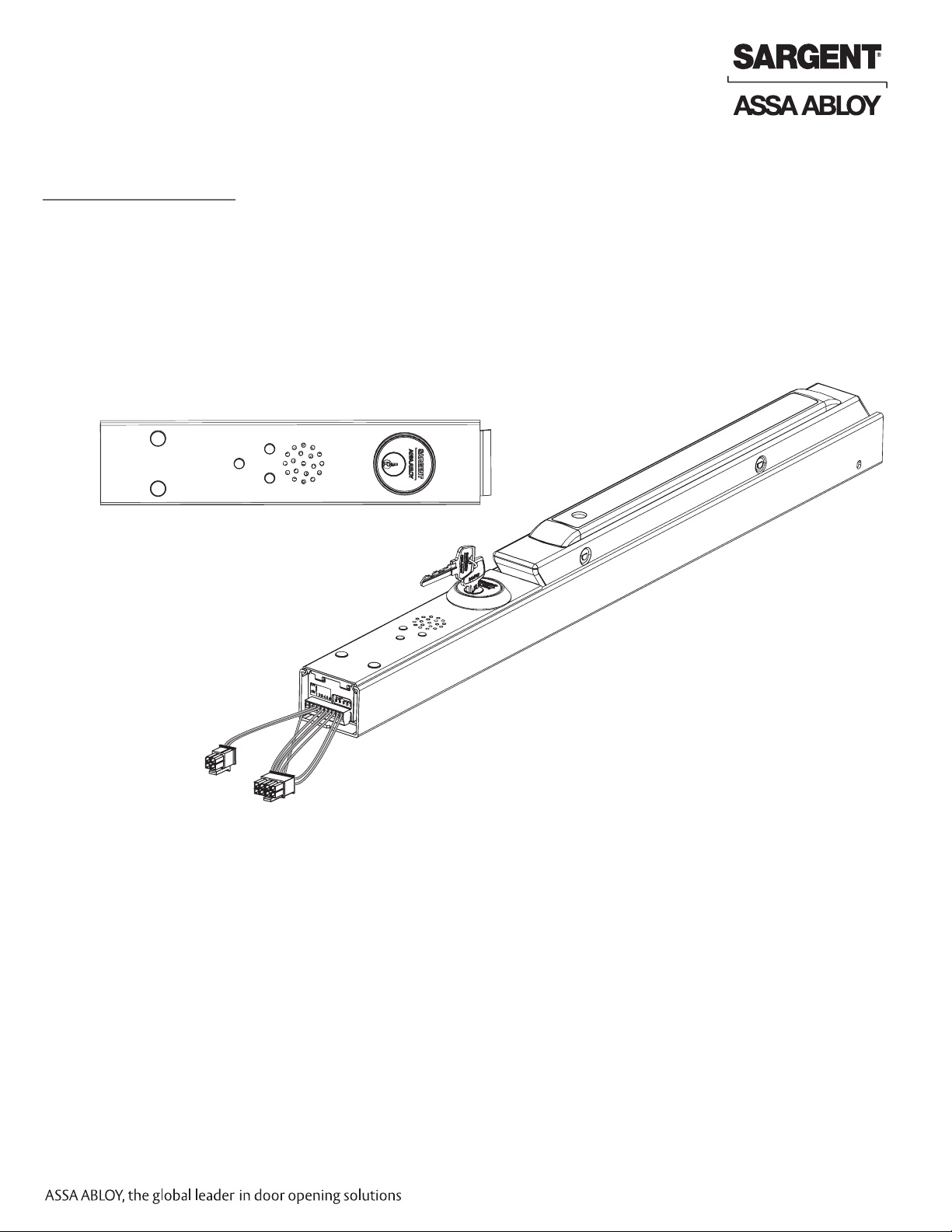
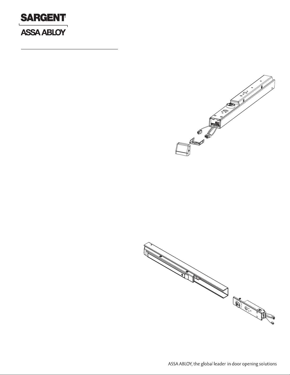
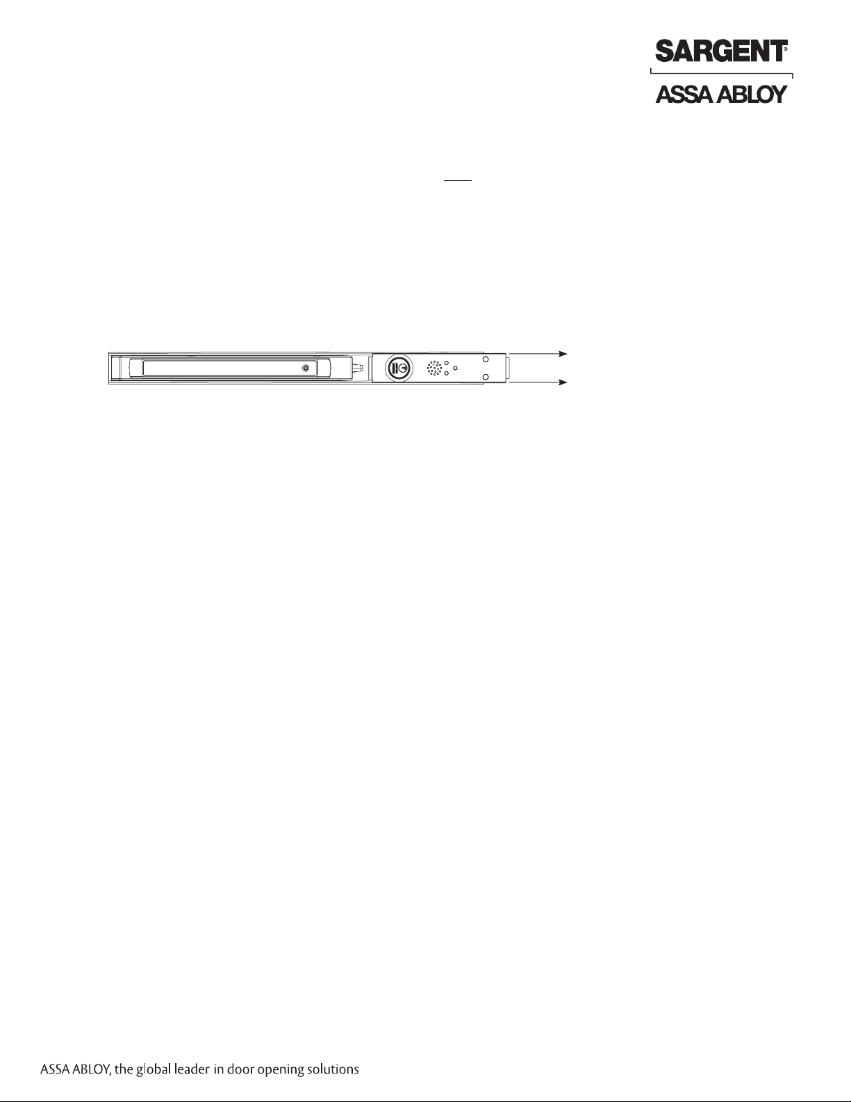
Beacon Exit Device
Installation and Wiring Instructions
FOR INSTALLATION ASSISTANCE CONTACT SARGENT • 1-800-810-WIRE (9473) • www.sargentlock.com
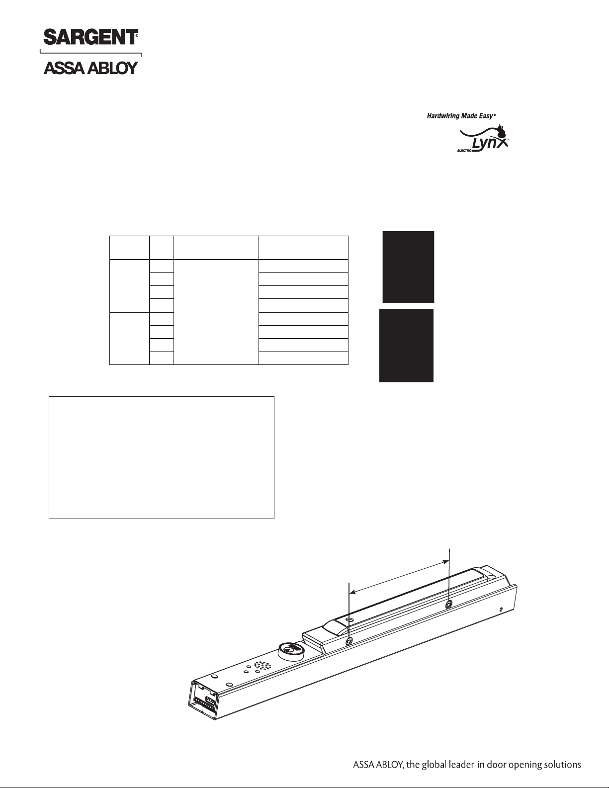
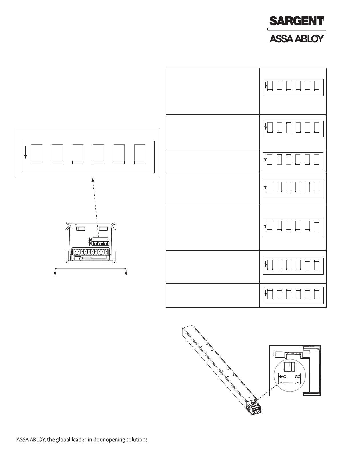
4. Alarm Mode Operation/Dip Switch Settings
• Two (2) WHITE LEDs flash continuously
• GREEN Laser ON 3 seconds
• ENGLISH message followed by
• GREEN Laser ON 3 seconds
• SPANISH message followed by
• GREEN Laser ON 3 seconds
• FRENCH message
• Two (2) WHITE LEDs flash continuously
• GREEN Laser ON 3 seconds
• ENGLISH message followed by
• GREEN Laser ON 3 seconds
• SPANISH message followed by
• Two (2) WHITE LEDs flash continuously
• GREEN Laser ON 3 seconds
• ENGLISH message only
• Two (2) WHITE LEDs flash continuously
• ENGLISH message followed by
• SPANISH message followed by
• FRENCH message
• (NO Green LASER)
• NO White LEDs
• GREEN Laser ON 3 seconds
• ENGLISH message followed by
• GREEN Laser ON 3 seconds
• SPANISH message followed by
• GREEN Laser ON 3 seconds
• FRENCH message
• NO White LEDs
• ENGLISH message followed by
• SPANISH message followed by
• FRENCH message
• (NO Green LASER)
• Trouble condition #4
• AMBER LED blinks 4 times and repeats
1 2 3 4 5 6
ON
1 2 3 4 5 6
ON
1 2 3 4 5 6
ON
1 2 3 4 5 6
ON
1 2 3 4 5 6
ON
1 2 3 4 5 6
ON
1 2 3 4 5 6
ON
A. Verify settings are correct for your facility’s
requirements.
NOTE: Device is shipped with factory default settings
(all switches ON - see Fig. 10 below).
Visual and audio (voice messages) will repeat sequence
in Alarm Mode.
If dip switch settings need to be changed from the factory
default, set according to chart (Fig. 11).
Door
Surface
ON
OFF 1 23456
English
Message
1 2 3 4 5 6
ON
Spanish
Message
French
Message
Not Used Green
Laser
Two White
High-Intensity
LEDs
Alarm Mode Operation Dip Switch Settings
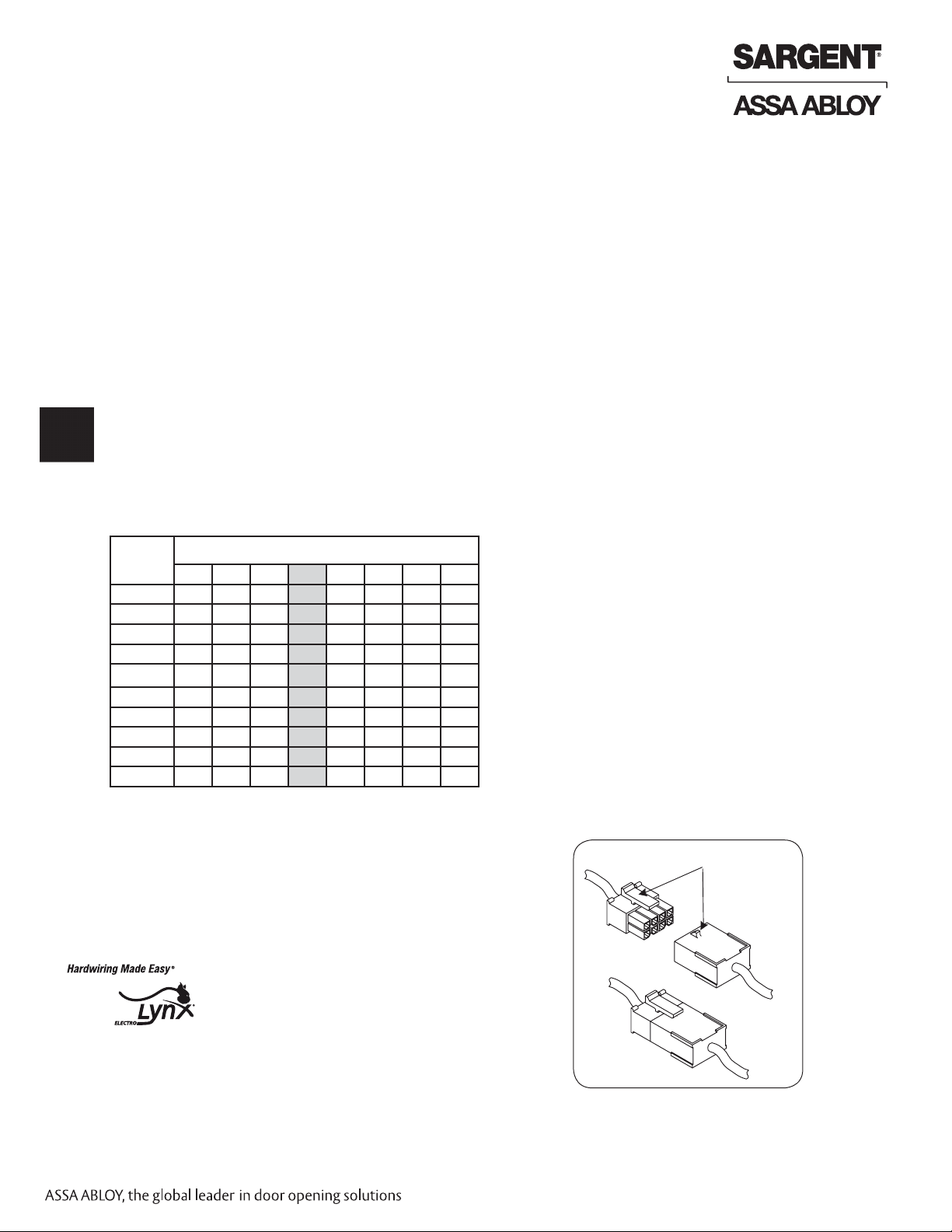
Factory default for NAC/CC switch is set to
CC (closed contact).
To change Beacon to NAC Alarm Mode:
A. Flip unit; slide insert assembly out 2 inches (Fig. 12).
B. Set the device for NAC by moving the slide switch
to the left, as shown in Figure 12.
C. Once switch is in proper position, slide insert
assembly back into rail assembly.
D. Refer to Section III NAC wiring examples
for proper wiring of NAC (vs. CC).
5. Alarm Notification Switch Setting (NAC/CC)
Fig. 12
Fig. 10
Fig. 11
Default Settings