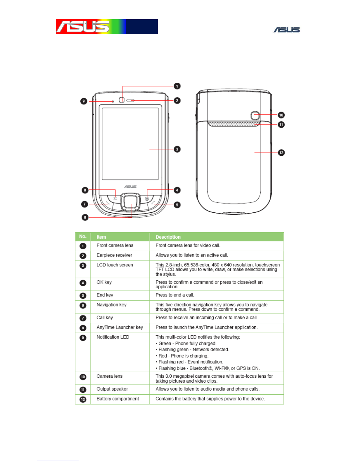
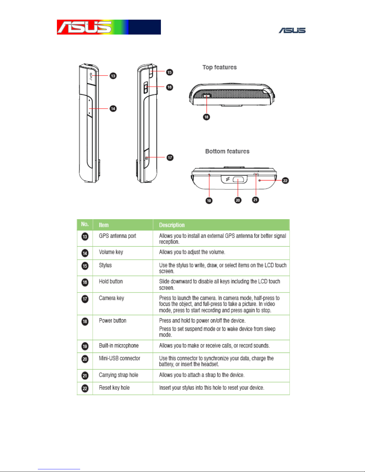
Asus P565 User manual

GTC ■Service Manual
1
華
華碩
碩電
電腦
腦
P565 Level 3,4
Trouble Shooting Guide
Ver 1.0

GTC ■Service Manual
2
華
華碩
碩電
電腦
腦
CONTENT
Chapter
1. OVERVIEW ..................................................................4
1.1 System Block Diagram 4
1.2 Power-On Sequence 5
1.3 Main Specification 7
1.4 Device exterior description 8
1.5 On Board Major Components Location 10
1.6 Debugging Equipments 12
2. Baseband Trouble Shooting .........................................15
2.1 Introduction 15
2.2 Device Cannot Power On 15
2.3 Device Peripheral Trouble Shooting 19
3. RF Trouble Shooting....................................................35
3.1 Equipment Requirements 35
3.2. RF Block Diagram 36
3.3. Procedures of RF Repair 39

GTC ■Service Manual
3
華
華碩
碩電
電腦
腦
Figure
Figure1 nBATT_FAULT Circuit................................17
Figure 2 Vibrator mechanism .....................................20
Figure 3 microSD Power ............................................21
Figure 4 Indication LED Circuit .................................22
Figure 5 Keypad LED Power......................................22
Figure 6 Camera power...............................................23
Figure 7 Camera Bus ..................................................24
Figure 8 Camera Bus ..................................................24
Figure 9 SIM Card Connector Circuit ........................25
Figure 10 Charger IC Circuit ........................................26
Figure 11 Battery Information Circuit ..........................27
Figure 12 SDRAM Circuit............................................28
Figure 13 Headset mechanism ......................................30
Figure 14 Class D Amp for speaker..............................32
Figure 15 Microphone Circuit.......................................33
Figure 16 Receiver Circuit............................................33
Appendix
1. Bluetooth Debug Tool Operation.................................85
2. WLAN Debug Tool Operation.....................................88
3. SiRF demo tool using ..................................................93
4. GPS firmware download..............................................97

GTC ■Service Manual
4
華
華碩
碩電
電腦
腦
1. OVERVIEW
1.1 System Block Diagram

GTC ■Service Manual
5
華
華碩
碩電
電腦
腦
1.2 Power-On Sequence
1.2.1
Start-up Timing Diagram

GTC ■Service Manual
6
華
華碩
碩電
電腦
腦
1.2.2 36KHz and 26MHz Start-up Timing
1.2.3 Power-On Sequence Check Point
a. VCC_BBAT_TAVOR
b. nHWRST_OUT_R
c. nBATT_LOW
d. 32KHz(TXTAL_IN)
e. SYS_EN
f. VCC_MVT
g. SYS_EN Power Group
h. PWR_EN
i. PWR_SDA,PWR_SCL
j. 26MHz
k. V_APP;V_COMM

GTC ■Service Manual
7
華
華碩
碩電
電腦
腦
1.3 Main Specification
Networks
HSDPA 3.6Mbps, UMTS 2100
EDGE/GPRS/GSM 900/1800/1900, Class 10
Operating System
Microsoft Windows® Mobile™ 6.1 Professional
CPU
Marvell Tavor 800MHz
Memory
256 MB Flash + 128MB SDRAM
Connectivity
WLAN 802.11b+g, USB v1.1(FS), Bluetooth 2.0+EDR
GPS
SiRF Star III with InstantFix
Display
2.8“, VGA 480 x 640, 65K, TFT
Camera
3 Mega-Pixel, Auto Focus
Battery
1300mAh Lithium
Weight
118g (with battery)
Standby Time
3G: 150-200 hours / 2G: 200~250 hours
Talk Time
3G: 3~5 hours / 2G: 4~6 hours
Expansion Slot
Micro-SD (support SDHC)
Browser
HTTP / WAP 1.2.1/2.0
Messaging
SMS / MMS / Email / MSN / Push E-mail
Video
MPEG4 : QVGA 24FPS / H.263 / .3gp : QCIF 24FPS
Video Call, Audio / Video Streaming
Picture
JPEG / PNG / GIP / BMP
Audio
MP3 / WMA / 3GP / AAC / AAC+
Ringtone
MP3 / MIDI
JAVA
J2ME (CLDC 1.1 + MIDP2.0)

GTC ■Service Manual
8
華
華碩
碩電
電腦
腦
1.4 Device exterior description
1.4.1 FRONT and BACK SIDE

GTC ■Service Manual
9
華
華碩
碩電
電腦
腦
1.4.2 OTHER SIDE

GTC ■Service Manual
10
華
華碩
碩電
電腦
腦
1.5 On Board Major Components Location
1.5.1 FRAON SIDE

GTC ■Service Manual
11
華
華碩
碩電
電腦
腦
1.5.2 BACKT SIDE

GTC ■Service Manual
12
華
華碩
碩電
電腦
腦
1.6 Debugging Equipments
Oscilloscope
Soldering Iron

GTC ■Service Manual
13
華
華碩
碩電
電腦
腦
Power Supply
Reheat fan

GTC ■Service Manual
14
華
華碩
碩電
電腦
腦
Voltmeter

GTC ■Service Manual
15
華
華碩
碩電
電腦
腦
2.Baseband Trouble Shooting
2.1 Introduction
The purpose of this repair manual is to provide a general trouble
shooting guide for the defective ASUS PDA phone ASGM5.
The repair methodology provided in this manual is strictly for the
ASGM5 model ONLY, trouble shooting methodology for the other ASUS
designed PDA phone will not be included in this document.
2.2 Device Cannot Power On
2.2.1 Measure each power-on sequence voltage level
The most common reasons that will cause device to fail to power on
is due to defect components or incorrect power-on sequence. It is
recommended to observe and examine if there is any obvious external
damage on the PCB or any on board component first. If not, please hook
the power supply and check if there is any current,。If there is no current
observed on power supply, please push the power button to power on the
system first and follow the following debugging process: V_BAT =
power supply voltage.
A. V_BAT = power supply voltage ,check C1103.1
This is to make sure that the power source is at the correct level. If
the measured voltage level is lower than the supplied main voltage, it is
likely that there is a current leakage on the V_BAT power domain.
(Generally this will cause high current consumption on the power supply).
If this is observed, please check all the components that are connected to
the V_BAT net, and examine if there is any possible defect. If the
measured voltage is equal to 0V, and it is not shorted to GND, please
check if there is any defect on the battery connector.。

GTC ■Service Manual
16
華
華碩
碩電
電腦
腦
B. VCC_BBAT= 2.9V
If VCC_BBAT is < 2.9V, please examine chip U901 and the
resistors/capacitors around it. Observe if there is any defect.
C. nBATT_FAULT(R321) = 2.9V
If incorrect voltage is observed, please examine any possible defect
on U303, U304, U305, U306 and the surrounding components.
D. 32KHz clock (TXTAL_IN)
If 32KHz clock signal is not measured, please examine any possible
defect on X301 and the surrounding components.
E. SYS_EN(U406.1) = 2.9V
SYS_EN is the signal that sends from the CPU to the PMU to
indicate power on sequence is running correctly up to this point, and can
continue to turn on certain power domains.
If SYS_EN voltage level is incorrect, it is likely there is a defect on the
CPU (U301).
F. VCC_MVT(R515)=1.8V;VBUCK3(C943.1)=2.1V;
VCC_MVT_PLL_CORE(R525)=1.8V;
VCC_MVT_CLK(R528)=1.8V;
LDO2(R927)=1.8V;
LDO3(R931)=2.8V
If incorrect voltage is measured on the above power domains, please
check if there is any defect on U901, L903, U301,U41 ,L8 ,L9 ,L10 and
the surrounding components.
G. PWR_EN (U304.2)= 2.9V
PWR_EN is a signal that sends from the CPU to the PMU to indicate
that power on sequence is running correctly upon this point, and the PMU
can proceed to turn on the remaining power domain required for the CPU.

GTC ■Service Manual
17
華
華碩
碩電
電腦
腦
If all the power domains measured in procedure 1-E are correct, but
PWR_EN is measured at an incorrect level, then it is most likely that
there is a defect on U901 or U301
H. Verify if V_COMM(R966) and V_APPS(R967) voltage level are
in the range of 0.9~1.4V. If not, please examine if there is any defect on
U901, U301 or the passive components
on this two power domains.
I. 26MHZ clock (26MHZ_SYS )
If 26MHz clock is not measured, please examine if there is any defect
on OSC1801,C1802, U1802 and the surrounding components.
Figure1. nBATT_FAULT Circuit

GTC ■Service Manual
18
華
華碩
碩電
電腦
腦
If all the voltage measurement performed in procedure 1 are all
normal, but the device is still unable to power up, it is advise to use the
oscilloscope to measure R433(OneNAND_nCS)
and observe if there is any high-low transition; If not, it is likely there is a
defect on U601 or U301; If high-low transition on R433 can be observed,
please measured TP610(SD0) and
verify if it also have high-low transition. If not, it is likely that there is a
defect on U605.
2.2.2 RTC can’t power on issue
Please check the following point, if it is all matched ,it’s defined as
a can’t-power-on issue
A. Measure the system current with power supply, it must be around
0mA.
B. Short push power button, system current is still not up.
C. Long push power button, system current is still not up.
D. HW reset(push the power button and reset key at the same
time),current is still not raising up.
E. Measure the voltage described above from A~E, according to the
experience the voltage level on PWR_EN and SYS_EN would be
abnormal(about 1.~ V)。
If above items have been done, and the system still can’t power on.
Please discharge the super cap(CE901).Use the tweezers to discharge the
supercap to ground until the voltage level on super cap down to 0.4V
Summary:
Measurement Check list for device unable to power on:
a) VCC_BBAT
b) nHWRST_OUT_R
c) nBATT_LOW
d) 32KHz(TXTAL_IN)
e) SYS_EN

GTC ■Service Manual
19
華
華碩
碩電
電腦
腦
f) VCC_MVT
g) SYS_EN Power Group
(VCC_MVT;VBUCK3;VCC_MVT_PLL_CORE;VCC_MVT_CLK;LDO2;LDO3)
h) PWR_EN
i) PWR_SDA,PWR_SCL
j) V_APP;V_COMM
k) 26MHz
l) OneNAND_nCS
m) SD0
2.3 Device Peripheral Trouble Shooting
(MMI Testing)
2.3.1 LCD Display Test
This test item is for LCM interface and backlight, if this item NG,
please check the following signal:
A. LCD_PWR_EN should be 1.8V
B. VCC_18V should be 1.8V
C. VCC_2.8V should be 2.8V
D. LCD_nRESET should be 2.9V
E. LCD_FCLK, LCD_LCLK, LCD_PCLK should have high-low
transaction, check if there is any
defect or open on componetR701, R702, R703.
F. LCD_DATA_EN should be 2.9V
The above signal could result in white screen, if
LCD_PWR_EN/LCD_RESET# signal is abnormal, it means CPLD is
NG. The signal LCD0 ~ LCD15 is from CPU, if the color of panel is
abnormal, please check component CON701 and CPU.
G. If there is no backlight, check the voltage on V_LED, there should be
12V. If backlight is
abnormal please check U1503 and the component around it.

GTC ■Service Manual
20
華
華碩
碩電
電腦
腦
2.3.2 Vibrator Test
If the vibrator is not functioning, please check if VIBRA_C0 voltage
is measured at 3V and also no defect is found on component R1516 or
D1501, then it is likely that U1505 is defective.
Figure 2 Vibrator mechanism
2.3.3 RTC Test
It is rare to observe this type of defect, but if it does occur, please
examine if X301 crystal is sending out 32.768KHz clock signal correctly.
If 32.768KHz crystal is running correctly, then it is likely that U301
(CPU)
2.3.4 Storage Test
It is also rare to observe this type of defect, but if it does occur, it is
likely that U601 is defective.
2.3.5 MicroSD Test
If the device is unable to read SD storage card, try to replace the
device with new a sub-board and perform the test again. If the defect is
still not solved, please follow the following debugging procedure:
A. Please verify if sub board(MicroSD board) and main board is
connected properly.
B. Please verify if CON1201 is defective.
C. Please verify if MMC_PWR_EN = 1.8V (On the sub board.) If not,
Other manuals for P565
1
Table of contents
Other Asus Cell Phone manuals

Asus
Asus Zenfone 4 Max User manual

Asus
Asus ZenFone V Live User manual

Asus
Asus X00BD User manual

Asus
Asus P552W User manual

Asus
Asus I007D User manual

Asus
Asus 02 Xda Graphite User manual

Asus
Asus VERIZON ZENFONE AR User manual

Asus
Asus VERIZON ZENFONE AR User manual

Asus
Asus X014D User manual

Asus
Asus M307 M307 User manual