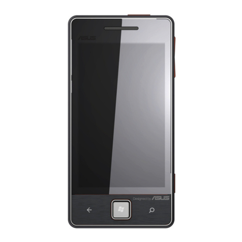
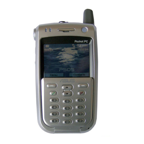
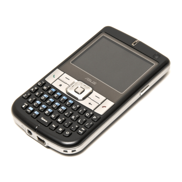
Asus P735 User manual

CSC
■
Lv3Lv4 Repair Manual
- 1 - ASUS Proprietary
華
華碩
碩電
電腦
腦
ASUS P735 Service Manual

CSC
■
Lv3Lv4 Repair Manual
- 2 - ASUS Proprietary
華
華碩
碩電
電腦
腦
Index
1.OVERVIEW ..........................................................................................................................5
1.2
T
EST STATION ARRANGEMENT IN
F
ACTORY AND
CSC........................................................5
2.CONFIGURAOR TOOL IN CSC .......................................................................................6
2.1
ASUS
R
ELEASE
W
AY FOR
CSC
C
ONFIGURATOR
T
OOL
......................................................6
2.4
T
OOL
’
S
I
NPUT AND
O
UTPUT FILE
.......................................................................................9
3.MAPPING TABLE IMPLEMENT ...................................................................................10
4.FIELD OF XML FILE EXPLANATION ......................................................................... 11
5.SIM LOCK PROCESS.......................................................................................................12
6.BASEBAND REPAIR ABSTRACT: .................................................................................13
7.INTRODUCTION...............................................................................................................13
8.1SPECIFICAITONS.........................................................................................................13
8.2
ID
C
ONCEPT
....................................................................................................................14
9.TEST SET AND TOOL ......................................................................................................14
9.1
P
OWER
S
UPPLY
...............................................................................................................14
9.2
O
SCILLOSCOPE
................................................................................................................15
9.3
M
ICROSCOPE
................................................................................................................15
9.4
O
THER
ME
T
OOL
..........................................................................................................15
9.5
P735
C
HARGER
.............................................................................................................16
10.PCBA OUTLOOK ............................................................................................................17
10.1
PCBA-
TOP
SIDE
........................................................................................................17
10.2
PCBA-
B
OTTOM SIDE
..................................................................................................18
11. UNDERFILL REWORK NOTICE ................................................................................19
11.1
S
COPE
: ..........................................................................................................................19
11.2
N
ECESSARY TOOL AND EQUIPMENT
:.........................................................................19
11.3
W
ORK METHOD
:.......................................................................................................19
11.4
P
RECAUTIONS
: ............................................................................................................20
11.5
U
NDER FILL
C
HIPS
L
OCATION
.....................................................................................20
12. P735 BLOCK DIAGRAM...............................................................................................21
13. P735 PRACTICAL REPAIRING FLOW DIAGRAM:................................................22
14. P735 REPAIR NOTICE PART :.....................................................................................23

CSC
■
Lv3Lv4 Repair Manual
- 3 - ASUS Proprietary
華
華碩
碩電
電腦
腦
14.1
SR
N
OTICE
L
IST
............................................................................................................23
14.2
ER1
N
OTICE
L
IST
..........................................................................................................23
14.3
ER2
N
OTICE
L
IST
..........................................................................................................24
15 TROUBLESHOOTING ...................................................................................................25
15.1
D
EBUG PROCESS
............................................................................................................25
15.2
R
EPAIR
C
ASE
.................................................................................................................26
S
YSTEM FAIL TO BOOT UP
......................................................................................................26
N
O BOOT
: ..............................................................................................................................26
LCD
P
ROBLEM
: ....................................................................................................................28
AUDIO.................................................................................................................................29
Receiver no sound ............................................................................................................29
Speaker no sound .............................................................................................................29
MIC no sound...................................................................................................................29
Fail to record ...................................................................................................................30
BLUE
TOOTH
ABNORMAL
..................................................................................................30
KEYPAD
ABNORMAL
...........................................................................................................30
SIDE KEY.........................................................................................................................30
Key pad FPC....................................................................................................................30
C
AMERA ABNORMAL
.............................................................................................................30
2M CAMERA no preview .................................................................................................30
Preview abnormal ............................................................................................................30
16. TROUBLE SHOOTING:................................................................................................31
16.1
Q
WERTY
K
EYPAD PROBLEM
: .........................................................................................31
16.2
M
ICRO
-SD
CARD PROBLEM
:..........................................................................................32
16.3
C
AMERA PROBLEM
:.......................................................................................................33
16.4
BT
PROBLEM
:................................................................................................................33
16.5
SIM
CARD PROBLEM
: ....................................................................................................34
16.6
A
UDIO PROBLEM
: ..........................................................................................................34
16.7
USB
PROBLEM
: .............................................................................................................36
16.8
S
WITCH CONNECTOR PROBLEM
: ....................................................................................37
16.9
V
IBRATOR PROBLEM
:.....................................................................................................37
17.POWER CONSUMPTION TEST...................................................................................38
17.1
E
NVIRONMENT
S
ETTING
................................................................................................38
17.2
D
EEP
S
LEEP
M
ODE
........................................................................................................38
17.3
S
TANDBY
M
ODE
/S
LEEP
M
ODE
......................................................................................39
17.4
C
HARGING
C
URRENT
T
EST
............................................................................................42

CSC
■
Lv3Lv4 Repair Manual
- 4 - ASUS Proprietary
華
華碩
碩電
電腦
腦
18. RF REPAIR SW & HW REQUIREMENT ...................................................................45
18.1
SW:............................................................................................................................45
18.2
HW:...........................................................................................................................45
18.3
E
QUIPMENT
:...............................................................................................................45
19. P735 RF BLOCK DIAGRAM ........................................................................................46
19.1
S
YSTEM
B
LOCK
D
IAGRAM
............................................................................................46
19.2
GSM/GPRS
–
GSM
RFMD
P
OLARIS
I
B
LOCK
D
IAGRAM
............................................47
19.3
WCDMA
–
M
AXIM
3G
B
LOCK
D
IAGRAM
....................................................................48
19.4
B
LUETOOTH
–
CSR
BC04
B
LOCK
D
IAGRAM
................................................................49
20. RF CIRCUIT TEST POINTS LOCATION...................................................................50
20.1
B
ACKSIDE
A
NTENNA
A
REA
T
EST
P
OINTS
......................................................................50
20.2
GSM/GPRS
T
EST
P
OINTS
.............................................................................................50
20.3 WCDMA TEST POINTS ..............................................................................................52
21. GSM & WCDMA RF TX/RX PATH..............................................................................53
21.1
GSM
T
X PATH
...............................................................................................................53
21.2
GSM
R
X PATH
...............................................................................................................53
21.3
WCDMA
T
X PATH
........................................................................................................54
21.4
WCDMA
R
X PATH
........................................................................................................54
22. RF TEST & REPAIR FLOW CHART ..........................................................................55
22.1.
C
ONDUCTIVE
&
A
NTENNA
T
EST
P
ROCEDURE
..............................................................55
22.3
WCDMA
T
EST
&
R
EPAIR
P
ROCEDURE
.........................................................................57
22.4
B
LUETOOTH
T
EST
&
R
EPAIR
P
ROCEDURE
.....................................................................59
23. TEST POINTS SIGNAL EXAMPLES ..........................................................................60
23.1
GSM900 .......................................................................................................................60
23.2
DCS1800......................................................................................................................63
23.3
PCS1900.......................................................................................................................66
23.4
WCDMA ......................................................................................................................69
23.5
B
LUETOOTH
..................................................................................................................75
24. APPENDIX .......................................................................................................................80
24.1
T
YPICAL
V
ALUE OF
GSM/GPRS
C
ONDUCTIVE
T
X
/
R
X
T
EST
.......................................80
24.2
T
YPICAL
V
ALUE OF
WCDMA
C
ONDUCTIVE
T
X
/R
X
T
EST
.............................................80
24.4
R
X
T
EST
E
NVIRONMENT
S
ETUP
.....................................................................................82

CSC
■
Lv3Lv4 Repair Manual
- 13 - ASUS Proprietary
華
華碩
碩電
電腦
腦
6.BaseBand Repair Abstract:
For the training, the document mainly describes how to repair P735 if main board was
damaged. Another topic focuses on EPE bug list from SR to DVT according to every run of
repairing experience.
7.Introduction
P735 WCDMA/GSM PDA phone
8.1SPECIFICAITONS
•Frequency Band: –GSM: Tri-band operation in GSM 900/1800/1900 networks
–UMTS: 3GPP Band •UE Class:
–GSM: Class B, Multi-slot Class 10
–WCDMA: 384 kbps Class (UL/DL 384k)
•Operation System: Microsoft Windows Mobile 6.0 OS
•3G RF/BB: Intel Hermon + Dual mode RF+AFE+PA
CPU: Marvelll PXA270 520 MHz
•Memory: 256MB Flash, 64 MB SDRAM
•Extended Memory: mini-SD Card
•Antenna: Build-in solution
•Bluetooth: Bluetooth V2.0 spec. Class 2
•3GPP Video Streaming and Video Telephony
•Messaging: SMS, MMS
•WAP2.0
•JAVA: MIDP2.0, JSR184, Etc•
•LCM: Main: 2.8” Toppoly 320*RGB*240 TFT(65K) include Touch Screen
•Dual Camera: 2.0M pixels with auto focus and VGA
•Connective: Bluetooth / USB1.1 (Client and Host) / mini-SD
•Audio: Speaker/ MIC/ Receiver
•Battery: Maxell 1300 mAh
3G 2M camera WM6.0
Bar type

CSC
■
Lv3Lv4 Repair Manual
- 14 - ASUS Proprietary
華
華碩
碩電
電腦
腦
8.2 ID Concept
9.Test Set and Tool
9.1 Power Supply
MOTECH programmable DC power Supply or equivalence *1

CSC
■
Lv3Lv4 Repair Manual
- 15 - ASUS Proprietary
華
華碩
碩電
電腦
腦
9.2 Oscilloscope
Tektrniox TDS5054B Digital Phosphor Oscilloscope or equivalence *1
( Bandwidth 200MHz )
9.3 Microscope
(10X,40X)
9.4 Other ME Tool
(Plastic wrench ,Screwdriver T5 and #00)

CSC
■
Lv3Lv4 Repair Manual
- 16 - ASUS Proprietary
華
華碩
碩電
電腦
腦
9.5 P735 Charger
The default charger adaptor for P735 is TAMURA PACIFIC JSP050090UC.
Meanwhile, P735 support USB charging with 500mA.

CSC
■
Lv3Lv4 Repair Manual
- 17 - ASUS Proprietary
華
華碩
碩電
電腦
腦
10.PCBA Outlook
10.1 PCBA- TOP side

CSC
■
Lv3Lv4 Repair Manual
- 18 - ASUS Proprietary
華
華碩
碩電
電腦
腦
10.2 PCBA- Bottom side

CSC
■
Lv3Lv4 Repair Manual
- 19 - ASUS Proprietary
華
華碩
碩電
電腦
腦
11. Underfill Rework Notice
Purpose:
Set up the underfill rework role, guarantee the quality that FAE repairs.
11.1 Scope:
Personnel that all is maintained and the reworked is correlated with
11.2 Necessary tool and equipment:
::
:
5.2.1 Iron:16-T00531807(SD-80)
5.2.2 Iron-head:16GPFT008046
5.2.3 Hot Air Gun:20-T004A3002
5.2.4 Solder Measurement device:16-000603100
5.2.5 Solder-wire:16GSST012011 (Lead free (T=0.6MM))
5.2.6 Flux:16GPCT001010 (αLead free EF-8000)
5.2.7 Cleaner:16GPCT020053 (IC-TS00)
5.2.8 Cotton
:
16-T00380809
(
315MM*10.5M
)
5.2.9 Solder paste
:
16GPCT022057 ( PF601)
11.3 Work method:
::
:
5.3.1 It must last 8 hours to toast PCB board by 125 degrees Centigrade before the
rework of underfill
。
5.3.2 Use the hot air gun to invite 10cm distance above the part and set up and heat
time as 20sec, use the tweezers to remove glueing in the white glue part of BGA.
5.3.3 Use BGA machine to remove the underfill part, the temperature is set up to 255
degrees, use the tweezers to remove component in the 10 sec lastly.
。
5.3.4 Use Iron and soldering paste to clean incomplete glue and soldering ball of PCB
PAD.
5.3.5 Remove incomplete glue and soldering ball of PCB, add the tin once again by
PCB PAD part, and visual have incomplete glue.
5.3.6 Whether it is intact and damaging to examine PCB PAD in item after using the
sanitizer to polish PCB PAD clean.
5.3.7 Use the soldering paste to daub on PCB PAD, put the new part and rework.

CSC
■
Lv3Lv4 Repair Manual
- 20 - ASUS Proprietary
華
華碩
碩電
電腦
腦
11.4 Precautions:
5.4.1 Before cleaning the glue movements, confirm whether the Iron temperature knob
pointed to "390 degrees Centigrade " scale.
5.4.2 Before cleaning the glue movements, really implement the ESD.
5.4.3 After using the cleaner to polish, and then observe the part and around have PU
incomplete glue.
5.4.4 While changing the part, there is a apt part damaged around to find the part , use
and defend.the sticky tape to protect, prevent the part from being destroyed.
11.5 Under fill Chips Location

CSC
■
Lv3Lv4 Repair Manual
- 21 - ASUS Proprietary
華
華碩
碩電
電腦
腦
12. P735 Block Diagram

CSC
■
Lv3Lv4 Repair Manual
- 22 - ASUS Proprietary
華
華碩
碩電
電腦
腦
13. P735 practical repairing flow diagram:
Boot?
Inspect consumed
current?
No
Yes
0 ~ 100mA:
Inspect power on
sequence
If the peripheral
devices are fail,
please follow
trou le shooting
guide line to de ug.
100 ~200mA:
Inspect hermon
interface (MSL) or
other damarged
peripheral chips
200~230mA:
Inspect crystal of
hermon and cpu or
cs(chip select)
No
Yes
START
STOP
1.prepare tools
2.set
voltage:3.8~4.2
V
3.set limited
current:2A
Run diagnosis
program
Show logo and
oot OS display
No
Yes
Run next test item
Yes
Yes
No
No
Over 300mA:
Inspect whether
PMU or peripheral
chip is leakage
current or not?
Yes
No
Yes

CSC
■
Lv3Lv4 Repair Manual
- 23 - ASUS Proprietary
華
華碩
碩電
電腦
腦
14. P735 Repair Notice Part :
14.1 SR Notice List
Station Problem
Symptom
Preliminary
Analysis
Root Cause Remark
SYS
MMI
Can not
preview form
camera
function.
Connector is
damaged or data
bus solders fail.
Connector is damaged by
operation problem to
cause preview fail.
SYS
MMI
SIM card fail SIM Connector
is damaged or
data bus pin fail.
can't build network lock,
so SIM card detect fail
SYS
MMI
No boot U1(CPU) or
(U20)PMU fail
SMT issue.(solder ball of
U1 is short circuit)
14.2 ER1 Notice List
Station Problem
Symptom
Preliminary
Analysis
Root Cause Remark
Board
level
MMI
MIC no
function
U19(codec) fail Solder ball of U19 is
short circuit to cause
MIC no function.
SYS
MMI
Can't not
preview
CMOS
PLL function of
CMOS fail, so it
can not preview
Walton camera module
fails (PLL). (camera
issue)
SYS LCD abnormal Topply LCD Modify SW image for

CSC
■
Lv3Lv4 Repair Manual
- 24 - ASUS Proprietary
華
華碩
碩電
電腦
腦
MMI display, 2mm
line
timing problem LCD timing.
SYS
MMI
LCD White
screen
LCD panel is fail
LCD is damaged in left
below side as shown
in report
SYS
MMI
LCD white fail
1.LCD backlight
not uniform, send
to vendor for
analysis
2. From vendor
analysis, the
mura was caused
by the assembly
issue of the B/L.
Toppoly LCD issue
14.3 ER2 Notice List
Station Problem
Symptom
Preliminary
Analysis
Root Cause Remark
Board
level
MMI
Sleep mode
current fail
CE3(RTC) is short
circuit, so it cause
leakage current in
standby mode
SMT issue
Board
level
MMI
Sleep mode
current fail
OS can not suspend
resume to cause
sleep mode current
fail.
U1(CPU) issue
Board
level
MMI
Sleep mode
current fail
leakage current is
from U20(PMU) to
cause charge fail
U20(PMU) issue.
Board
level
MMI
Earphone_L
FREQ FAIL
Audio amplify L
path fail cause to
earphone L freq no
sound
U14(audio amp.)
issue

CSC
■
Lv3Lv4 Repair Manual
- 25 - ASUS Proprietary
華
華碩
碩電
電腦
腦
15 Troubleshooting
15.1 Debug process
No
YES
Yes
Inspect PCBA
(any chip or mechanical
component damaged ?)
Inspect consumed
current
Run diagnosis app.
Pass all test items?
Repair O.K
Current abnormal
Rework
Damaged Component
Fail

CSC
■
Lv3Lv4 Repair Manual
- 26 - ASUS Proprietary
華
華碩
碩電
電腦
腦
15.2 Repair Case
System fail to boot up
1. if consumed current is zero,inspect battery connector if normal。
2. if consumed current is above normal (300~500mA),touch and feel any chip if
getting heat abnormally。
3. If consumed current is increasing to 180mA, and while after, become zero. It often
means Bulverde abnormal, check Bulverde first if solder crack, chip
damaged, X’tal abnormal (32.768KHz and 13 MHz) and etc.
4. If system hangs at the following display, it often means Hermon abnormal.
Sometimes, it caused by PMIC ADC error, therefore, cause HW version
detection error.
5. If current going down suddenly to 0 mA while booting
a. Inspect power domain and clock of Bulverde and Hermon。
b. Inspect Bulverde power on sequence, clarify CPU side problem or
PMIC side problem。
No boot:
1.
Inspect power on timing of CPU and PMU as show in Pig.3 and Pig. 4, if the current = 0
mA.
2.
Inspect PMU power domain such as LDO and Buck voltage, if the current = 40 ~ 60mA.
3.
Inspect hermon interface, if the current = 100 ~ 200mA
4.
Inspect crystal of hermon and CPU or CS (Chip Select) from flash memory, if the current
= 200 ~ 230mA.
5.
If the consumed current is over 300mA, please check PMU, peripheral device and other
chip.
Bulverde power on sequence and timing

CSC
■
Lv3Lv4 Repair Manual
- 27 - ASUS Proprietary
華
華碩
碩電
電腦
腦
Hermon power on sequence and timing
Sys_EN C224 PWR_EN D30 nReset TP71

CSC
■
Lv3Lv4 Repair Manual
- 28 - ASUS Proprietary
華
華碩
碩電
電腦
腦
LCD Problem:
1.
Inspect LCD connector and power on signals, which are LCD_VDD (R49.1) and
nLCD_RST (R49.2), as shown in Pig 5-1, if panel can not monitor.
2.
Inspect PCLK (C80.2) signal of CPU as shown in Pig.5-2, if panel appear white monitor.
3.
Inspect FCLK (C779.2)signal of CPU as shown in of Pig.5-2, if panel appear horizontal
line.
4.
Inspect LCLK (C780.2)signal of CPU as shown in of Pig.5-2, if panel appear shift
monitor.
5.
Inspect LCD back light driver as shown in Pig.5-3, if panel can not drive back light.
Pig.5-1 61 pin of LCD connector and power domain located in P735 bottom side
Pig.5-2 PCLK, FCLK and LCLK
Other manuals for P735
2
Table of contents
Other Asus Cell Phone manuals

Asus
Asus Zenfone 2 Z00D User manual

Asus
Asus M930 User manual

Asus
Asus ZenFone 5 User manual

Asus
Asus Zenfone Ares User manual

Asus
Asus Zenfone 3 ZE552KL User manual

Asus
Asus Zenfone Max pro M2 User manual

Asus
Asus V66 Handset Manager User manual

Asus
Asus M307 M307 User manual

Asus
Asus 02 Xda Graphite User manual

Asus
Asus ZENFONE2 ZE500KL User manual

Asus
Asus ZB552KL User manual

Asus
Asus ZenFone Max Plus ZB570TL User manual

Asus
Asus J102 Assembly instructions

Asus
Asus PadFone Station User manual

Asus
Asus ZenFone 4 Guide

Asus
Asus Z00VD User manual

Asus
Asus X00BD User manual

Asus
Asus P835 User manual

Asus
Asus ROG Phone User manual

Asus
Asus ZenFone Max Pro M1 Technical manual