ATIKA BTU 450 User manual

Baukreissäge
Montageanleitung
Construction circular saw
Assembly instructions
Scie circulaire de chantier
Instructions de montage
Cirkulární pila
Montážní návod
Sega circolare per cantieri
Istruzioni di montaggio
Bouwcirkelzaag
Montage-instructie
Piła tarczowa budowlana
Instrukcja montażu
Ferăstrău circular pentru construcţii
Instrucţiuni de montaj
Cirkulárna píla
Montážny návod
BTU 450

2
Lieferumfang – Extent of delivery – Fouriture – Obsah dodávky -
A szállítás terjedelme – Standard di fornitura - Leveringsomvang
Zakres dostawy - Volumi de livrare - - Obsah dodávky
1
11
21
2
12
22
3
2x
13
23
4
2x
14
24
5 15
25
6
16
26
7
17 27
8
18
28
2x
9
19
2x 29
10
2x
20
29
30

3
34
Schraubenbeutel kpl.–Fastener bag (consisting of) –Sachet à vis (compose de)–
Sáček na šrouby (skládající se z)- Confezione di viti (bestehend aus) - Schroevenzak (bestaande uit)
Worek na śruby (składający się z) - - Pungă cu şuruburi
(constând din) - - Pungă cu şuruburi (skladá sa z)
35
40
46
51
4x
32x M6x16
4x St 4,9x13
4x M12x35
36
41
47
52
2x
49x A6,4
1x
2x A13
37
42 48
53
1x Ø 55mm
33x M6
1x M4x12
4x M12
38
43
49 54
4x – Ø 30mm
24x M8x20
1x A4
2x M6x12
39
44
50
55
48x A8,4
2x M6x12
45
56
1x
24x M8
1x M4
2x M6x60

4
Sie dürfen die Baukreissäge nicht in Betrieb nehmen,
bevor Sie die Betriebsanleitung gelesen, alle ange-
gebenen Hinweise beachtet und das Gerät wie be-
schrieben montiert haben.
Lieferumfang
Überprüfen Sie den Karton auf
Vollständigkeit
evtl. Transportschäden
Teilen Sie Beanstandungen umgehend dem Händler, Zulieferer bzw. Hersteller mit. Spätere Reklamationen werden nicht anerkannt.
1. Sägeblatt
2. Sägetischplatte kpl.
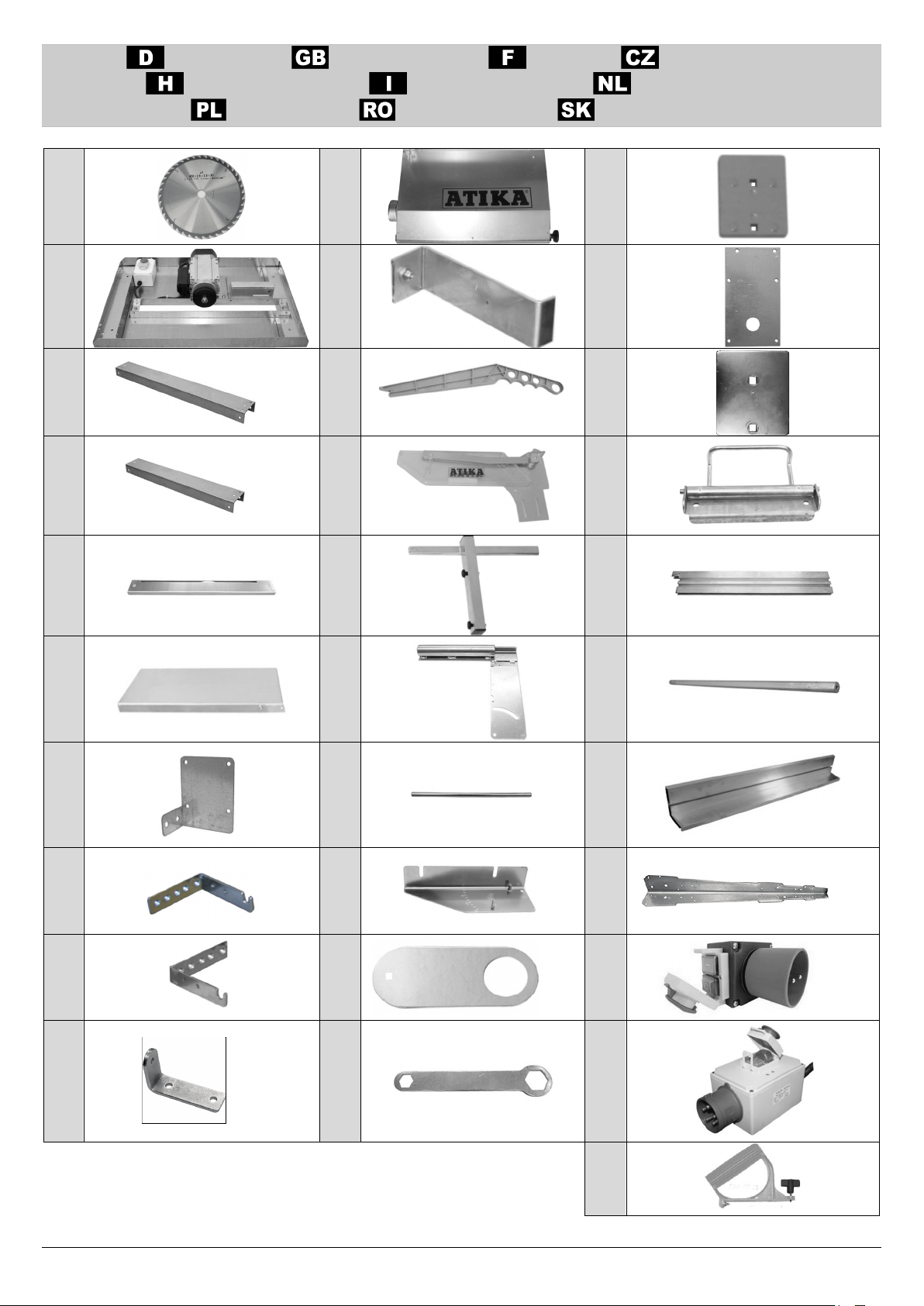
3. Strebe – lang (2 Stück)
4. Strebe – kurz (2 Stück)
5. Tischeinlage
6. Tischverlängerung
7. Schaltersockel (230V)
8. Schwenkhalter rechts für Tischverlängerung
9. Schwenkhalter links für Tischverlängerung
10. Halter für Führungswelle (2 Stück)
11. Spankasten mit Absaugstutzen
12. Keilschneidanschlag (mit Aluschraube und Alumutter)
13. Schiebestock
14. Spaltkeil mit Schutzhaube
15. Längsanschlag ohne Anschlaglineal
16. Anschlagführung
17. Haltedorn
18. Anschlagwinkel
19. Transportöse (2 Stück)
20. Ringschlüssel
21. Spaltkeilführung
22. Schaltersockel (400 V 3~)
23. Druckplatte für Spaltkeil
24. Klemmvorrichtung für Längsanschlag
25. Anschlagleiste
26. Führungswelle
27. Anschlaglineal
28. Tischbein (4 Stück)
29. Schalter-Steckerkombination (230V / 400V 3~)
30. Handgriff für Schiebeholz
31. Betriebsanleitung o. Abb.
32. Garantieerklärung o. Abb.
33. Montageanleitung o. Abb.
34. Schraubenbeutel bestehend aus:*
35. Aufsteckfüße (4 Stück)
36. Druckplatte für Transportösen (2 Stück)
37. Sterngriff M6 - Ø 55 mm
38. Sterngriff klein M6 - Ø 30mm (4 Stück)
39. Werkzeughaken
40. Sechskantschraube M6 x 16 mm (32 Stück)
41. Scheibe A6,4 (49 Stück)
42. Sechskantmutter M6 (33 Stück)
43. Sechskantschraube M8 x 20 (24 Stück)
44. Scheibe A8,4 (48 Stück)
45. Sechskantmutter M8 (24 Stück)
46. Blechschraube St 4,8 x 13 mm (4 Stück)
47. Kabelschelle
48. Zylinderschraube M4x12mm
49. Scheibe A4
50. Sechskantmutter M4
51. Flachrundschraube M12x35 (4 Stück)
52. Scheibe A13 (2 Stück)
53. Mutter M12 (4 Stück)
54. Sechskantschraube mit Flansch M6 x 12 (2 Stück)
55. Zylinderschraube M6 x 12
56. Sechskantschraube M6 x 60 (2 Stück)
*Hinweis: Sollten Schrauben, Scheiben oder Muttern nach der Mon-
tage der Säge übrigbleiben, so ist dieses gewollt.
Symbole der Montageanleitung
Drohende Gefahr oder gefährliche Situation. Das Nichtbe-
achten dieser Hinweise kann Verletzungen zur Folge haben
oder zu Sachbeschädigung führen.
Wichtige Hinweise zum sachgerechten Umgang
. Das
Nichtbeachten dieser Hinweise kann zu Störungen führen.
Benutzerhinweise. Diese Hinweise helfen Ihnen, alle Funk-
tionen optimal zu nutzen.
Montagehinweis. Es werden zwei Personen benötigt.
Bei Problemen mit der Montage setzten Sie sich bitte mit unse-
rem Kundendienst in Verbindung.
0 82 22 / 4130
- 605
- 607
- 613
- 622
- 625

5
You may not start to operate the construction cir-
cular saw until you have read these operating in-
structions, observed all the instructions given and
installed the machine as described.
Extent of delivery
After unpacking, check the contents of the box
That it is complete
Check for possible transport damage
Report any damage or missing items to your dealer, supplier or the manufacturer immediately. Complaints made at a later date will not be
acknowledged.
1. Saw blade
2. Saw table board
3. Brace, long (2 pieces)
4. Brace, short (2 pieces)
5. Table insert
6. Table extension
7. Switch base for single-phase power supply
8. Swiveling holder RH for table extension
9. Swiveling holder LH for table extension
10. Holder for guide shaft (2 pieces)
11. Chip box with extraction nozzle
12. Wedge cutting stop
13. Push stick
14. Splitting wedge with Protective guard
15. Parallel stop without guide ruler
16. Stop guide
17. Retaining pin (pivot pin)
18. Stop angle
19. Transport lug
20. Ring wrench
21. Splitting wedge guide
22. Switch base for three-phase power supply
23. Pressing plate for splitting wedge
24. Clamping device for parallel stop
25. Stop bar
26. Guide shaft
27. Stop ruler
28. Table leg (4 pieces)
29. Switch-connector-combination (230V / 400V 3~)
30. Push block handle
31. Operating manual, without picture
32. Warranty declaration, without picture
33. Assembly instructions, without picture
34. Fastener bag (consisting of)*
35. Slip in foot (4 pieces)
36. Pressing plate for transport lug (2 pieces)
37. Star grip M6 - Ø 55 mm
38. Star grip small M6 - Ø 30mm (4 pieces)
39. Tool hook
40. Hexagon head screw M6 x 16 mm (32 pieces)
41. Washer A6,4 (39 pieces)
42. Hexagon head screw M6 (33 pieces)
43. Hexagon head screw M8 x 20 (24 pieces)
44. Washer A8,4 (48 pieces)
45. Nut M8 (24 pieces)
46. Sheet metal screws St 4,8 x 13 mm (2 pieces)
47. Cable clamp
48. Pan head screw M4x12mm
49. Washer A4
50. Nut M4
51. Mushroom head square neck screw M12x35 (4 pieces)
52. Washer A13 (2 pieces)
53. Nut M12 (4 pieces)
54. Hexagon flange bolt M6 x 12 (2 pieces)
55. Pan head screw M6 x 12
56. Hexagon head screw M6 x 60 (2 pieces)
*Note: If screws, washers or nuts remain after the saw has been
assembled, this is intentional.
Symbols in the assembly instructions
Threatened hazard or hazardous situation. Not observing this instruction can lead to injuries or cause damage to property.
Important information on proper handling. Not observing this instruction can lead to faults.
User information. This information helps you to use all the functions optimally.
Assembly note. Two people are needed.

6
Ne pas mettre en service la scie circulaire de chan-
tier avant d'avoir lu la notice d'instruction. Monter la
machine conformément à la description en respec-
tant toutes les consignes indiquées.
Fourniture
Après le déballage de la machine, vérifiez le contenu du carton quant à
l’intégralité des pièces
la présence éventuelle de dommages dus au transport.
Informez immédiatement le revendeur, le transporteur et / ou le fabricant en cas de réclamation. Sachez que les réclamations ultérieures ne sont
plus acceptées.
1. Lame de scie
2. Table de la scie
3. Entretoise – longue (2 pièces)
4. Entretoise – courte (2 pièces)
5. Insert de table
6. Rallonge de table
7. Socle d'interrupteur CA
8. Support pivotant droit pour rallonge de table
9. Support pivotant gauche pour rallonge de table
10. Support de la barre de guidage (2 pièces)
11. Caisson à copeaux avec tubulure d'aspiration
12. Butée de coupure de coins (avec vis en alu et écrou en alu)
13. Baguette coulissante
14. Couteau diviseur avec capot de protection
15. Butée longitudinale
16. Guidage de butée
17. Mandrin porte-outil (goupille rotative)
18. Equerre
19. Œillet de transport (2 pièces)
20. Clé polygonale
21. Guidage du couteau diviseur
22. Socle d'interrupteur triphasé
23. Plaque d'appui pour couteau diviseur
24. Dispositif de serrage pour butée longitudinale
25. Baguette de butée
26. Barre de guidage
27. Règle de butée
28. Pied de table (4 pièces)
29. Connecteur-interrupteur combiné (CA, courant triphasé)
30. La poignée pour le bois coulissant
31. Notice d'instructions (sans illustration)
32. Déclaration de garantie (sans illustration)
33. Instructions de montage (sans illustration)
34. Sachet à vis (compose de)*
35. Embase de pied (4 pièces)
36. Plaque d'appui pour œillet de transport (2 pièces)
37. Poignée-étoile M6 - Ø 55 mm
38. Poignée-étoile M6 - Ø 30mm (4 pièces)
39. Le crochet à outils
40. Vis à six pans M6 x 16 mm (32 pièces)
41. Rondelle A6,4 (39 pièces)
42. Écrou M6 (33 pièces)
43. Vis à six pans M8 x 20 (24 pièces)
44. Rondelle A8,4 (48 pièces)
45. Écrou M8 (24 pièces)
46. Vis à tôle St 4,8 x 13 mm (2 pièces)
47. Le collier pour câbes
48. Vis cylindrique M4x12mm
49. Rondelle A4
50. Écrou M4
51. Boulon à tête bombée M12x35 (4 pièces)
52. Rondelle A13 (2 pièces)
53. Écrou M12 (4 pièces)
54. Vis à six pans avec flanc M6 x 12 (2 pièces)
55. Vis cylindrique M6 x 12
56. Vis à six pans M6 x 60 (2 pièces)
* Avis : S’il reste des vis, des rondelles ou des écrous après le mon-
tage, ceci est normal.
Symboles de la notice de montage
Danger imminent ou situation dangereuse. L’inobservation de ces indications peut entraîner des blessures ou des dégâts matériels.
Indications importantes pour un emploi conforme à l’usage prévu. L’inobservation de ces indications peut provoquer des
dysfonctionnements.
Indications pour l’usager. Ces indications sont d’une aide précieuse pour un emploi optimal des différentes fonctions.
Consigne de montage. Deux personnes sont nécessaires.

7
Okružní pilu nesmíte uvést do provozu bez přečtení
návodu, dodržení v něm uvedených pokynů a
řádného sestavení pily podle tohoto popisu.
Obsah dodávky
Po rozbalení kartonu zkontrolujte obsah na-
úplnosti dodávky
event.škod způsobených dopravou
Zjištěné nedostatky neprodleně oznamte svému dodavateli resp.výrobci.Na pozdější reklamace nebude brán zřetel.
1. Pilový kotouč (tvrzená ocel)
2. Pracovní deska – dlouhá (2 kusy)
3. Pracovní deska – krátká (2 kusy)
4. Vzpěra krátká
5. Stolní vložka
6. Prodloužení stolu
7. Držák spínače pro motor 230 V
8. Kyvný držák pravý pro prodloužení stolu
9. kyvný držák levý pro prodloužení stolu
10. Držák vodící hřídele (2 kusy)
11. Pilinová schránka s hrdlem pro odsávání
12. Klínový doraz (s hliníkovým šroubem a hliníkovou maticí)
13. Dřevěná posuvka materiálu
14. Rozvorný klín s ochranným krytem
15. Podélný doraz
16. Dorazové vodítko
17. Držný trn
18. Úhlový doraz
19. Transportní osa (2 kusy)
20. Očkový klíč
21. Vedení rozvorného klínu
22. Držák spínače pro 3 fázový motor
23. Přítlačná deska na štípací klín
24. Přípravek pro připevnění podélného dorazu
25. Dorazová lišta
26. Vodící část
27. Dorazový lineál
28. Stolní noha
29. Spínač / vypínač kombinace (230 V, pro 3 fázový motor)
30. Rukoväť pre posunovač
31. Notice d'instructions (bez obrázku)
32. Déclaration de garantie (bez obrázku)
33. Instructions de montage (bez obrázku)
34. Sáček na šrouby (skládající se z)*
35. Násada na nohu (4 kusy)
36. Přítlačná deska pro přepravní oka (2 kusy)
37. Hvězdicová matice M6 - Ø 55 mm
38. Hvězdicová matice M6 - Ø 30mm (4 kusy)
39. Háky na nářadí
40. Šesťhranná skrutka M6 x 16 mm (32 kusy)
41. Podložka A6,4 (49 kusy)
42. Matice M6 (2 kusy)
43. Šesťhranná skrutka M8 x 20 (24 kusy)
44. Podložka A8,4 (48 kusy)
45. Matice M8 (24 kusy)
46. Šroub do plechu St 4,8 x 13 mm (24 kusy)
47. Kabelová příchytka
48. Šroub se sýrovou hlavou M4x12mm
49. Podložka A4
50. Matice M4
51. Šroub s plochou kulovou hlavou M12x35 (4 kusy)
52. Podložka A13 (2 kusy)
53. Matice M12 (4 kusy)
54. Šestistranný šroub s přírubou M6 x 12 (2 kusy)
55. Šroub se sýrovou hlavou M6 x 12
56. Šesťhranná skrutka M6 x 60 (2 kusy)
* Upozornění: Jestliže vám po montáži pily zůstanou nějaké šrouby,
podložky nebo matice, má to svůj důvod.
Symboly v návodu na sestavení pily
Hrozící nebezpečí nebo nebezpečná situace. Zanedbání těchto pokynů může mít za následek zranění nebo způsobení věcných škod.
Důležité pokyny ke správnému využití stroje. nedbání těchto pokynů může zapřičinit poruchy.
Uživatelské pokyny. Tyto pokyny Vám pomohou stroj optimálně využívat.
Pokyn k montáži. Jsou potřeba dvě osoby.

8
Non mettere in funzione la sega circolare senza
avere prima letto le presenti istruzioni per l’uso,
avere osservato tutte le norme specificate e avere
montato l’apparecchio nel modo descritto.
Standard di fornitura
Una volta disimballato l'apparecchio, verificare se il contenuto della scatola
è completo;
presenta eventuali danni imputabili al trasporto.
Comunicare immediatamente al rivenditore, al fornitore o al costruttore eventuali contestazioni. Non verranno presi in considerazione i reclami
presentati in un momento successivo.
1. Lama della sega
2. Piano banco della sega
3. Profilato lungo (2 pezzi)
4. Profilato corto (2 pezzi)
5. Inserto banco
6. Prolunga banco
7. Zoccolo (corrente alternata)
8. Staffa perno dx per prolunga banco
9. Staffa perno sx per prolunga banco
10. Supporto per albero guida (2 pezzi)
11. Cassetta raccoglitrucioli con manicotto di aspirazione
12. Guida di arresto per taglio a cuneo
(con vite e dado in alluminio)
13. Asta di spinta
14. Cuneo con cappa di protezione
15. Arresto longitudinale
16. Guida di arresto
17. Spina di bloccaggio
18. Angolare di arresto
19. Golfare
20. Chiave poligonale
21. Guida del cuneo
22. Zoccolo (corrente trifase)
23. Piastra di pressione per cuneo
24. Dispositivo di serraggio per arresto longitudinale
25. Listello di battuta
26. Albero guida
27. Riga a T
28. Gamba del banco (4 pezzi)
29. Combinazione di connettori
(corrente alternata, corrente trifase)
30. Impugnatura per lo spintore
31. Istruzioni per l’uso, senza immagine
32. Dichiarazione di garanzia, senza immagine
33. Istruzioni di montaggio, senza immagine
34. Confezione di viti (bestehend aus)*
35. Piedino ad incastro (4 pezzi)
36. Piastra di pressione per golfare (2 pezzi)
37. Manopola a stella M6 - Ø 55 mm
38. Manopola a stella M6 - Ø 30mm (4 pezzi)
39. Gancio portautensili
40. Vite a testa esagonale M6 x 16 mm (32 pezzi)
41. Rondella A6,4 (49 pezzi)
42. Dado M6 (33 pezzi)
43. Vite a testa esagonale M8 x 20 (24 pezzi)
44. Rondella A8,4 (48 pezzi)
45. Dado M8 (24 pezzi)
46. Vite per lamiera St 4,8 x 13 mm (4 pezzi)
47. Fascetta per cavi
48. Vite a testa cilindrica M4x12mm
49. Rondella A4
50. Dado M4
51. Vite con testa a calotta piana M12x35 (4 pezzi)
52. Rondella A13 (2 pezzi)
53. Dado M12 (4 pezzi)
54. Vite a testa esagonale con flangia M6 x 12 (2 pezzi)
55. Vite a testa cilindrica M6 x 12
56. Vite a testa esagonale M6 x 60 (2 pezzi)
* Avviso: se dopo il montaggio della sega dovessero avanzare viti,
rondelle o dadi, è perfettamente normale.
Simboli delle istruzioni di montaggio
Potenziale pericolo o situazione pericolosa. La mancata osservanza di questo avviso potrebbe causare lesioni o danni materiali.
Avvisi importanti per un utilizzo conforme. La mancata osservanza di queste indicazioni può causare dei guasti.
Avvisi per l’utente. Queste indicazioni sono un valido aiuto per utilizzare in maniera ottimale tutte le funzioni.
Indicazione di montaggio. Sono necessarie due persone.

9
U mag de bouwcirkelzaag niet in gebruik nemen,
alvorens u deze gebruiksaanwijzing heeft gelezen,
alle vermelde voorschriften heeft opgevolgd en het
toestel als voorgeschreven heeft gemonteerd.
Leveringsomvang
Controleer na het uitpakken de inhoud van de verpakking op:
Aanwezigheid van alle onderdelen
Eventuele transportschade
In het geval van onvolkomenheden dit direct aan uw leverancier melden. Latere reclamaties worden niet in behandeling genomen.
1. Hardmetaalzaagblad
2. Zaagtafelblad
3. Steun – lang (2 stuks)
4. Steun – kort (2 stuks)
5. Tafelinzetstuk
6. Tafelverlenging
7. Schakelaarsokkel (wisselstroom)
8. Zwenkhouder rechts v. tafelverlenging
9. Zwenkhouder links voor tafelverlenging
10. Houder voor geleidingsas (2 stuks)
11. Spankast met afzuigstuk
12. Wigsnijdaanslag (met aluminium schroef en aluminium moer)
13. Schuifstok
14. Splijtwig met beschermkap
15. Langsaanslag
16. Aanslaggeleiding
17. Houddoom
18. Aanslaghoek
19. Transportoog
20. Ringsleutel
21. Splijtwiggeleiding
22. Schakelaarsokkel (draaistroom)
23. Drukplaat voor splijtwig
24. Klemvoorziening voor langsaanslag
25. Aanslaglijst
26. Geleidingsas
27. Aanslagliniaal
28. Tafelpoot (4 stuks)
29. Schakelaarstekercombinatie (wisselstroom, draaistroom)
30. Handvat voor het duwhout
31. Bedieningshandleiding, zonder afbeelding
32. Garantieverklaring, zonder afbeelding
33. Montage-instructie, zonder afbeelding
34. Schroevenzak (bestaande uit)*
35. Opsteekvoet (4 stuks)
36. Drukplaat voor transportoog (2 stuks)
37. Stergreep M6 - Ø 55 mm
38. Stergreep M6 - Ø 30mm (4 stuks)
39. Werktuighaak
40. Zeskantbout M6 x 16 mm (32 stuks)
41. Schijf A6,4 (49 stuks)
42. Moer M6 (33 stuks)
43. Zeskantbout M8 x 20 (24 stuks)
44. Schijf A8,4 (48 stuks)
45. Moer M8 (24 stuks)
46. Tapschroef St 4,8 x 13 mm (4 stuks)
47. Kabelklem
48. Cilinderbout M4x12mm
49. Schijf A4
50. Moer M4
51. Slotbout M12x35 (4 stuks)
52. Schijf A13 (2 stuks)
53. Moer M12 (4 stuks)
54. Zeskantbout mit Flansch M6 x 12 (2 stuks)
55. Cilinderbout M6 x 12
56. Zeskantbout M6 x 60 (2 stuks)
* Opmerking: Als er na de montage van de zaag nog schroeven,
ringen of moeren over zijn, is dat opzettelijk.
Symbolen van de montage-instructie
Dreigend gevaar of gevaarlijke situatie. Het niet opvolgen van deze aanwijzingen kan schade of verwondingen tot gevolg hebben.
Belangrijke aanwijzing voor het vakkundig gebruik. Het niet opvolgen van deze aanwijzingen kan storingen aan de machine
veroorzaken.
Gebruikersaanwijzingen. Deze aanwijzingen helpen u de machine optimaal te benutten.
Montagevoorschrift. Er zijn twee personen nodig.

10
Przed uruchomieniem urządzenia należy zapoznać
się z niniejszą instrukcją obsługi, zastosować się do
wszystkich podanych wskazówek i zamontować
urządzenie zgodnie z opisem.
Zakres dostawy
Po rozpakowaniu zawartości kartonów sprawdź
ich kompletności
ewentualnych uszkodzeń transportowych
Swoje zastrzeżenia zgłoś natychmiast sprzedawcy, dostawcy lub producentowi Późniejsze reklamacje nie będą uznawane.
1. Tarcza tnąca z wkładkami ze stopów
2. Blat stołu piły
3. Podpora – długa (2 sztuki)
4. Podpora – krótka (2 sztuki)
5. Wkładka stołu
6. Przedłużenie stołu
7. Podstawa wyłącznika jednofazowego
8. Uchwyt przechylny prawy do przedłużenia stołu
9. Uchwyt przechylny lewy do przedłużenia stołu
10. Uchwyt na wałek prowadzący
11. Pojemnik na wióra z króćcem wyciągowym
12. Ogranicznik do cięć kątowych
13. Popychacz
14. Klin z osłoną
15. Ogranicznik wzdłużny
16. Prowadnica ogran.
17. Trzpień przytrzymujący
18. Ogranicznik kątowy
19. Ucho transportowe(2 sztuki)
20. Klucz oczkowy
21. Wprowadzenie klina rozdzielającego
22. Podstawa wyłącznika trójfazowego
23. Płyta dociskowa
24. Zacisk do ogranicznika wzdłużnego
25. Ogranicznik listwowy
26. Wałek prowadzący
27. Liniał
28. Noga stołu (4 sztuki)
29. Układ wtyczek bezpieczeństwa (prąd jedno- i trjfazowy)
30. Uchwyt przesuwadła
31. Instrukcja obsługi, bez ilustracji
32. Deklaracja gwarancyjna, bez ilustracji
33. Instrukcja montażu, bez ilustracji
34. Worek na śruby (składający się z)*
35. Stopa nakładana (4 sztuki)
36. Druckplatten für Transportösen (2 sztuki)
37. Uchwyt gwiazdowy M6 - Ø 55 mm
38. Uchwyt gwiazdowy M6 - Ø 30mm (4 sztuki)
39. Hak narzędzia
40. Śruba sześciokątna M6 x 16 mm (32 sztuki)
41. Podkładka A6,4 (49 sztuki)
42. Nakrętka M6 (33 sztuki)
43. Śruba sześciokątna M8 x 20 (24 sztuki)
44. Podkładka A8,4 (48 sztuki)
45. Nakrętka M8 (24 sztuki)
46. Wkręt do blachy St 4,8 x 13 mm (4 sztuki)
47. uchwytu kablowego
48. Śruba z łbem walcowym M4x12mm
49. Podkładka A4
50. Nakrętka M4
51. Śruba płaska okrągła M12x35 (4 sztuki)
52. Podkładka A13 (2 sztuki)
53. Nakrętka M12 (4 sztuki)
54. Śruba sześciokątna mit Flansch M6 x 12 (2 sztuki)
55. Śruba z łbem walcowym M6 x 12
56. Śruba sześciokątna M6 x 60 (2 sztuki)
*Wskazówka: Pozostawienie po zmontowaniu piły śrub, podkładek lub
nakrętek jest zamierzonym działaniem.
Symbole w instrukcji montażu
Zagrażające niebezpieczeństwo lub niebezpieczna sytuacja. Nieprzestrzeganie niniejszych wskazówek może prowadzić w następstwie do
odniesienia obrażeń lub wystąpienia szkód rzeczowych.
Ważne wskazówki dotyczące prawidłowej obsługi. Nieprzestrzeganie niniejszych wskazówek może prowadzić w następstwie do zakłóceń w
pracy urządzenia.
Wskazówki dla użytkownika. Wskazówki te pomagają w optymalnym wykorzystaniu wszystkich funkcji urządzenia.
Wskazówka dotycząca montażu Potrzebne są dwie osoby.

11
Este interzisă punerea în funcţiune a ferăstrăului
circular înaintea citirii acestor instrucţiuni de folosire,
a respectării tuturor indicaţiilor şi a montării apara-
tului conform descrierii!.
Volumul de livrare
Verificaţi după despachetare dacă conţinutul cartonului
este complet
şi dacă nu a fost deteriorat în timpul transportului
Transmiteţi reclamaţiile imediat comerciantului sau furnizorului. Reclamaţiile ulterioare nu se iau în considerare.
1. Pânză de ferăstrău de metal dur
2. Placa mesei ferăstrăului
3. Bară-lungă (2 piese)
4. Bară-scurtă (2 piese)
5. Suport al mesei
6. Prelungire masă
7. Soclu de comutator (curent alternativ)
8. Suport rabatabil dreapta pentru prelungirea mesei
9. Suport rabatabil stânga pentru prelungirea mesei
10. Suport pentru ax de ghidare (2 piese)
11. Cutie de rumeguş cu ştuţuri de aspirare
12. Opritor tăiere în formă de pană
(Cu șurub din aluminiu și piuliță din aluminiu)
13. Bară de împingere
14. Pană de despicat cu carcasă de protecţie
15. Opritor longitudinal
16. Ghidajul opritorului
17. Dorn port-scule
18. Cornier opritor
19. Ureche de transport (2 piese)
20. Cheie inelară
21. Ghidaj pană de despicat
22. Soclu de comutator (curent trifazat)
23. Placă de presiune
24. Dispozitiv de prindere pentru opritorul longitudinal
25. Bară opritor
26. Ax de ghidare
27. Teu
28. Piciorul mesei (4 piese)
29. Combinaţie ştecăr/comutator
(curent alternativ, curent continuu)
30. Mâner pentru împingătorul din lemn
31. Instrucţiune de folosire, fără ilustraţie
32. Declaraţie de garanţie, fără ilustraţie
33. Instrucţiuni de montaj, fără ilustraţie
34. Pungă cu şuruburi (constând din)*
35. Picior de prindere (4 piese)
36. Placă de presiune pentru ureche de transport (2 piese)
37. Mâner în formă de stea M6 - Ø 55 mm
38. Mâner în formă de stea M6 - Ø 30mm (4 piese)
39. Cârlig unealtă
40. Şurub cu cap hexagonal M6 x 16 mm (32 piese)
41. Şaiba A6,4 (49 piese)
42. Piuliță M6 (33 piese)
43. Şurub cu cap hexagonal M8 x 20 (24 piese)
44. Şaiba A8,4 (48 piese)
45. Piuliță M8 (24 piese)
46. Şurub de prindere a tablei St 4,8 x 13 mm (4 piese)
47. Brățara pentru cabluri
48. Şurub cu cap cilindric M4x12mm
49. Şaiba A4
50. Piuliță M4
51. Şurub cu cap rotund înecat M12x35 (4 piese)
52. Şaiba A13 (2 piese)
53. Piuliță M12 (4 piese)
54. Şurub cu cap hexagonal mit Flansch M6 x 12 (2 piese)
55. Şurub cu cap cilindric M6 x 12
56. Şurub cu cap hexagonal M6 x 60 (2 piese)
* Notă: Dacă după instalarea fierăstrăului rămân șuruburi, șaibe sau
piulițe, acestea sunt lăsate aşa intenționat.
Simbolurile din instrucţiunile de montaj
Pericol iminent sau situaţie periculoasă. Nerespectarea acestor indicaţii poate cauza accidentări sau daune materiale.
Indicaţii importante privind utilizarea competentă. Nerespectarea acestor indicaţii poate duce la perturbaţii.
Instrucţiuni de folosire. Aceste indicaţii vă ajută să folosiţi în mod optim toate funcţiile.
Indicație de montaj Este necesară participarea a două persoane.

12
Pílu nesmiete uviesť do prevádzky, pokiaľ si
neprečítate tento návod, nedodržíte všetky uvedené
pokyny a pílu riadne nezostavite..
Obsah dodávky
Stroj skontrolujte z hľadiska
úplnosti dodávky
prípadných škôd spôsobených dopravou
Zistené nedostatky ihneď oznámte svojmu dodávateľovi resp. výrobcovi. Na neskoršie reklamácie nebude braný ohľad.
1. Pílový kotúč
2. Pracovná doska
3. Vzpera dlhá (2 kusy)
4. Vzpera krátka (2 kusy)
5. Stolová vložka
6. Predĺženie stola
7. Držiak spínača pre motor (curent alternativ)
8. Kyvadlový držiak pravý na predĺženie stola
9. Kyvadlový držiak ľavý na predĺženie stola
10. Držiak pre vodiacej hriadeľ (2 kusy)
11. Pilinová skrinka s hrdlom pre odsávanie
12. Klínový doraz (s hliníkovou skrutkou a hliníkovou maticou)
13. Dřevěná posuvka materiálu
14. Rozvorny klin s ochranným krytom
15. Pozdľžný doraz
16. Dorazové vodítko
17. Držný trň
18. Cornier opritor
19. Ureche de transport (2 kusy)
20. Cheie inelară
21. Ghidaj pană de despicat
22. Soclu de comutator curent trifazat
23. Placă de presiune
24. Dispozitiv de prindere pentru opritorul longitudinal
25. Bară opritor
26. Ax de ghidare
27. Teu
28. Piciorul mesei
29.
Combinaţie ştecăr/comutator
(curent alternativ, curent continuu)
30. Posuvného dreveného dielu
31. Instrucţiune de folosire, bez vyobrazenia
32. Declaraţie de garanţie, bez vyobrazenia
33. Instrucţiuni de montaj, bez vyobrazenia
34. Pungă cu şuruburi (skladá sa z)*
35. Picior de prindere (4 kusy)
36. Dřevěná posuvka materiálu - Ureche de transport (2 kusy)
37. Hviezdicová matka M6 - Ø 55 mm
38. Hviezdicová matka M6 - Ø 30mm (4 kusy)
39. háčik na obrobky
40. Šesťhranná skrutka M6 x 16 mm (32 kusy)
41. Podložka A6,4 (49 kusy)
42. Matica M6 (33 kusy)
43. Šesťhranná skrutka M8 x 20 (24 kusy)
44. Podložka A8,4 (48 kusy)
45. Matica M8 (24 kusy)
46. Blechschraube St 4,8 x 13 mm (4 kusy)
47. Kabelschelle
48. skrutka s valcovou hlavou M4x12mm
49. Podložka A4
50. Matica M4
51. Skrutka s trojhrannou hlavou M12x35 (4 kusy)
52. Podložka A13 (2 kusy)
53. Matica M12 (4 kusy)
54. Šesťhranná skrutka mit Flansch M6 x 12 (2 kusy)
55. skrutka s valcovou hlavou M6 x 12
56. Šesťhranná skrutka M6 x 60 (2 kusy)
* Upozornenie: Ak po montáži píly zostanú skrutky, podložky alebo
matice, je to zámerné.
Symboly v návode na zostavenie stroja
Hroziace nebezpečie alebo nebezpečná situácia. Zanedbanie týchto pokynov môže mať za následok zranenie alebo spôsobenie
vecných škôd.
Dôležité pokyny na správne využitie stroja. Nedodržanie týchto pokynov môže zapríčiniť poruchy.
Užívateľské pokyny. Tieto pokyny Vám pomôžu stroj optimálne využívať.
Upozornenie k montáži. Montáž si vyžaduje dve osoby.

13
Heben Sie die Sägetischplatte (Gewicht 37 kg) mit
zwei Personen aus dem Karton.
Legen Sie die Sägetischplatte (2) mit der Arbeitsfläche nach unten
auf eine geeignete Unterlage.
Lift the saw table plate (weight 37 kg) with two
persons from the carton.
Place the saw table board (2) on a suited surface with the work sur-
face down.
Sortir la table de la scie (poids 37 kg) du carton à
deux.
Poser la table de la scie (2) sur un support approprié, la surface de
travail étant orientée vers le bas.
Pracovní desku pily (hmotnost 37 kg) musí z kartonového obalu vyzvednout dvě osoby.
Položte stůl pily (2), pracovní plochou dolů, na vhodný podklad.
sollevare in due persone il piano del banco della sega (peso 37 kg) per toglierlo dalla scatola.
Posizionare la piastra del banco della sega (2) su una base adeguata con la superficie di lavoro verso il basso.
Til het zaagtafelblad (gewicht 37 kg) met twee personen uit het karton.
Leg de zaagtafelplaat (2) met de werkvlakte naar beneden op een geschikte ondergrond.
Blat stołu pilarki (ciężar 37 kg) z kartonu podnoszą dwie osoby.
Stół piły (2) odłożyć na odpowiednie podłoże powierzchnią roboczą skierowaną w dół.
Ridicați placa mesei fierăstrăului (greutate 37 kg) din cutie cu ajutorul a două persoane.
Aşezaţi placa mesei ferăstrăului (2) cu suprafaţa de lucru în jos pe un suport potrivit.
Vyťahujte dosku stola píly (hmotnosť 37 kg) z krabice dvaja.
Položiťe stôl píly(2) pracovnou plochou nadol,na určený podklad.
Schrauben Sie den Spankasten (11) mit
4 Sechskantschrauben [M6 x 16], 8 Scheiben
[A6,4] und 4 Muttern [M6] an die Sägetischplatte.
Screw the chip box (11) using
4 hexagon head screws [M6x16] each with 8
washers [A6.4] and 4 nuts [M6] on the saw table
board.
Visser le caisson à copeaux (11) sur la table de la
scie à l'aide des 4 vis à six pans [M6x16] en utili-
sant 8 rondelles [A6, 4] et 4 écrous [M6] corres-
pondants.
Přišroubujte pilinovou schránku (11) čtyřmi
4 šestihrannými šrouby [M6x16] s 8 podložkami
[A6,4] a 4 maticemi [M6] ke stolu.
Avvitare la cassetta raccogli trucioli (11) alla piastra del banco della sega con 4 viti a testa esagonali [M6x16], 8 rondelle [A6,4] e 4 dadi [M6].
Schroef de spankast (11) met telkens 4 zeskantschroeven [M6x16], 8 schijven [A6,4] en 4 moeren [M6] aan de zaagtafelplaat.
Przykręcić pojemnik na wióra (11) za pomocą 4 śrub [M6x16], 8 podkładek [A6,4] i4 nakrętek [M6] do stołu piły.
Înşurubaţi cutia de rumeguş (11) cu câte 4 şuruburi cu cap hexagonal [M6x16], 8 şaibe [A6,4] şi 4 piuliţe [M6] de placa mesei ferăstrăului.
Priskrútkujte pílinovú skrínku (11) 4 skrútkami [M6x16] s 8 podložkami [A6,4] a 4 maticami [M6] ke stolu

14
Schrauben Sie die 4 Tischbeine (28) an -
je Tischbein 4 Sechskantschrauben [M6 x 16],
4 Scheiben [A6,4] und 4 Muttern [M6].
Befestigen Sie das Tischbein mit dem Sicher-
heitsaufkleber (A) an der gezeigten Stelle.
Ziehen Sie die Schrauben noch nicht fest!
Screw on the table legs (28) -for each leg use
4 hexagon head screws [M6x16], 4 washers [A6.4] and
4 nuts [M6].
Mount the table leg with the safety label (A) on the
shown location.
Do not yet tighten the screws (leave them hand-
tight).
Visser les pieds de la table (28) à l'aide des
4 vis à six pans [M6 x 16] en utilisant 4 rondelles [A6,4]
et 4 écrous [M6] correspondants.
Fixer le pied de la table avec l'autocollant de sé-
curité (A) à l'endroit indiqué.
Ne pas encore serrer les vis !
Přišroubujte nohy (28). (každou 4 šestihranným šroubem [M6x16] s 4 podložkou [A6,4] a 4 maticí [M6])
Nohu, která je opatřená bezpečnostní samolepkou (A), připevněte na příslušné místo podle nákresu.
Šrouby ještě neutahujte pevně!
Avvitare le gambe del banco (28) (quattro viti a testa esagonale [M6x16], 4 rondelle [A6,4] e 4 dadi [M6]).
Fissare la gamba del banco con le etichette di sicurezza (A) nel punto indicato.
Aspettare ad avvitare saldamente le viti!
Schroef de tafelbenen (28) aan (telkens 4 zeskantschroeven [M6x16], 4 schijven [A6,4] en 4 moeren [M6]).
Bevestig het tafelbeen met de veiligheidssticker (A) aan de getoonde plaats.
Trek de schroeven nog niet vast!
Przykręcić nogi stołu (28) (cztery 4 śruby [M6x16], 4 podkładki [A6,4] i 4 nakrętki [M6]).
Przymocować nogę stołu z naklejką bezpieczeństwa (A) w pokazanym miejscu.
Nie dokręcać jeszcze całkowicie śrub!
Înşurubaţi picioarele mesei (28) (cu câte patru 4 şuruburi cu cap hexagonal [M6x16], 4 şaibe [A6,4] şi 4 piuliţe [M6]).
Fixaţi pe piciorul mesei autocolantele privind siguranţa (A) în locul indicat.
Nu strângeţi încă definitiv şuruburile!
Priskrútkujte stolné nohy (28) (každú 4 skrútkou [M6x16] s 4 podložkou [A6,4] a 4 maticou [M6]).
Noha, ktorá je opatrená bezpečnostnou samolepkou (A), pripevnite na miesto podľa nákresu.
Skrútky ešte nepritiahniťe pevne!

15
Montieren Sie den Rahmen aus je zwei Streben-
lang (3) und zwei Streben-kurz (4).
Verbinden Sie jeweils eine kurze und eine lange
Strebe mit
2 Sechskantschrauben [M8 x 20],
4 Scheiben [A8,4] und 2 Muttern [M8] .
Ziehen Sie die Schrauben noch nicht fest!
Setzen Sie dann den vormontierten Rahmen in
die Säge ein.
Sie benötigen dafür eine zweite Person.
Assemble the frame from two long struts (3) and
two short struts (4).
Connect one short and one long strut each with
2 hexagon head screws [M8x20], 2 washers
[A8.4] and 2 nuts [M8].
Do not tighten the screws firmly!
Then insert the pre-assembled frame into the
saw.
You need a second person for this.
Monter le cadre à partir de respectivement deux entretoises longues (3) et deux entretoises courtes (4).
Raccorder respectivement une entretoise courte et une entretoise longue avec 2 vis à six pans [M8 x 20], 4 rondelles [A8,4] et 2 écrous [M8].
Ne pas encore serrer les vis !
Intégrer ensuite le cadre prémonté dans la scie. Faites-vous aider par une deuxième personne.
Rám smontujte ze dvou dlouhých příček (3) a ze dvou krátkých příček (4).
Krátkou a dlouhou příčku spojte vždy 2 šestistrannými šrouby [M8 x 20], 4 podložkami [A8,4] a 2 maticemi [M8].
Šrouby zatím ještě zcela neutahujte!
Následně vložte předem smontovaný rám do pily. K tomu je potřeba ještě jedna osoba.
Montare il telaio composto rispettivamente da due sostegni lunghi (3) e due sostegni corti (4).
Unire ciascun sostegno corto e lungo con 2 viti a testa esagonale [M8 x 20], 4 rondelle [A8,4] e 2 dadi [M8].
Aspettare ad avvitare saldamente le viti.!
Per eseguire questa operazione è richiesto l’aiuto di una seconda
persona.
Inserire quindi il telaio premontato nella sega.
Zet het frame in elkaar met twee lange stangen (3) en twee korte stangen (4).
Verbind telkens een korte en een lange stang met twee zeskantschroeven [M8 x 20], vier ringen [A8,4] en twee moeren [M8].
Trek de schroeven nog niet vast!
Zet dan het voorgemonteerde frame in de zaag.
U benodigt hiervoor een tweede persoon.
Zmontować ramę z dwóch długich rozpórek (3) i dwóch krótkich rozpórek (4).
Połączyć po jednej krótkiej i jednej długiej rozpórce za pomocą 2 śrub z łbem sześciokątnym [M8 x 20], 4 podkładek [A8.4] i 2 nakrętek [M8].
Nie dokręcać jeszcze całkowicie śrub!
Następnie włożyć wstępnie zmontowaną ramę do piły.
Do tej czynności potrzebne są dwie osoby.
Asamblați cadrul din două bare-lungi (3) și două bare-scurte (4).
Conectați o bară scurtă și o bară lungă cu 2 șuruburi hexagonale [M8 x 20], 4 șaibe [A8,4] și 2 piulițe [M8].
Nu strângeţi încă definitiv şuruburile!
Apoi introduceți cadrul preasamblat în fierăstrău.
Pentru aceasta, aveţi nevoie şi de o a doua persoană .
Zostavte rám z dvoch dlhých vzpier (3) a dvoch krátkych vzpier (4).
Krátku a dlhú vzperu spojte pomocou 2 skrutiek so šesťhrannou hlavou [M8 x 20], 4 podložiek [A8,4] a 2 matíc [M8].
Skrútky ešte nepritiahnite pevne!
Potom do píly vložte vopred zostavený rám.
Na to je potrebná druhá osoba.

16
Befestigen Sie den Rahmen an jeder Ecke mit
je 4 Sechskantschrauben [M 8 x 20],
8 Scheiben [A8,4] und 4 Muttern [M8] an den
Tischbeinen.
Ziehen Sie die Schrauben noch nicht fest
an!
Attach the frame to each corner with each
4 hexagon head screws [M8x20], 4 washers
[A8.4] and 4 nuts [M8] to the table legs.
Do not yet tighten the screws (leave them
hand-tight).
Fixer le cadre de chaque côté avec respectivement 4 vis à six pans [M 8 x 20], 8 rondelles [A8,4] et 4 écrous [M8] aux pieds de table.
Ne pas encore serrer les vis !
V každém rohu rám připevněte k nohám stolu vždy 4 šestistrannými šrouby [M 8 x 20], 8 podložkami [A8,4] a 4 maticemi [M8].
Šrouby ještě neutahujte pevně!
Fissare il telaio alle gambe del banco utilizzando rispettivamente 4 viti a testa esagonale [M8 x 20], 8 rondelle [A8,4] e 4 dadi [M8] per ogni angolo.
Aspettare ad avvitare saldamente le viti.
Bevestig het frame op elke hoek met telkens vier zeskantschroeven [M 8 x 20], acht ringen [A8,4] en vier moeren [M8] aan de tafelpoten.
Trek de schroeven nog niet vast!
Przymocować ramę do nóg stołu w każdym rogu za pomocą 4 śrub sześciokątnych [M8 x 20], 8 podkładek [A8.4] i 4 nakrętek [M8].
Nie dokręcać jeszcze całkowicie śrub!
Atașați cadrul la picioarele mesei, la fiecare colț, cu 4 șuruburi hexagonale [M 8 x 20], 8 șaibe [A8,4] și 4 piulițe [M8].
Nu strângeţi încă definitiv şuruburile!
Rám pripevnite k nohám stolu v každom rohu pomocou 4 skrutiek so šesťhrannou hlavou [M 8 x 20], 8 podložiek [A8,4] a 4 matíc [M8].
Skrútky ešte nepritiahnite pevne!
Schlagen Sie die Aufsteckfüße (35) auf die
Tischbeine.
Tap the slip on feet (35) on the table legs.
Engager les embouts (35) sur les pieds de
table.
Na nohy natlučte návleky (35).
Colpire i piedini (35) sulle gambe del banco.
Sla de opsteekvoeten (35) op de tafelbenen.
Przykręcić nogi nasadowe (35) do nóg stołu.
Bateţi piciorul de prindere (35) la picioarele
mesei.
Na nohy nabiťe dolníky (35).

17
Befestigen Sie die Klemmvorrichtung für den
Längsanschlag (24) mit
2 Sechskantschrauben [M6 x 16],
4 Scheiben [A6,4] und 2 Muttern [M6].
Mount the clamping device for the parallel stop
(24) using
2 hexagon head screws [M6 x 16],
4 washers [A6.4] and 2 nuts [M6].
Fixer le dispositif de serrage de la butée longi-
tudinale (24) à l'aide des
2 vis à six pans [M 6 x 16] en utilisant les
4 rondelles [A6,4] et les 2 écrous [M6] corres-
pondants.
Připevněte přípravek pro připevnění podélného dorazu (25) 2šestihrannými šrouby [M6 x 16], 4 podložkami [A6,4] a 4 maticemi [M6].
Fissare il dispositivo di serraggio per l’arresto longitudinale (24) con 2 viti a testa esagonale [M6 x 16], 4 rondelle [A6,4] e 2 dadi [M6].
Bevestig de klemvoorziening voor de langsaanslag (24) met 2 zeskantschroeven [M6 x 16], 4 schijven en [A6,4] 2 moeren [M6].
Przykręcić zacisk do ogranicznika wzdłużnego (24) za pomocą 2 śrub [M6 x 16], 4 podkładek [A6,4] i 2 nakrętek [M6]..
Prindeţi dispozitivul de fixare pentru opritorul longitudinal (24) cu 2 şuruburi cu cap hexagonal [M6 x 16], 4 şaibe [A6,4] şi 2 piuliţe [M6].
Pripevnite prípravok pre pripevnenie pzdľžného dorazu (24) skrútkami [M6 x 16], podložkami [A6,4] a maticami [M6].
Ausführung 230V: Schaltersockel (7) - Ausführung 400V 3~ : Schaltersockel (22):
Befestigen Sie den Schaltersockel (7 oder 22) mit je 2 Sechskantschrauben [M6 x 16] und 2 Muttern [M6] an der Sägetischplatte.
Version single-phase 230V: switch base (7) - Version three-phase power 400V 3~: switch base (22)
Mount the switch base (7 or 22) on the saw table board using 2 hexagon head screws [M6 x 16] and nuts [M6] each.
Version à courant alternatif (230 V): socle de l'interrupteur (7) - Version à courant triphasé 400V 3~ : socle de l'interrupteur (22):
Fixer le socle de l'interrupteur (7 ou 22) sur la table de la scie à l'aide des 2 vis à six pans [M6 x 16] en utilisant des 2 écrous [M6] correspondants.
Verze motor na střídavý proud 230V: Držák spínače (7) - Verze třífázový motor 400V 3~ : Držák spínače (22):
Připevněte podstavu pro spínač (7 nebo 22) dvěma 2 šestihrannými šrouby [M6 x 16] a 2 maticemi [M6] ke stolní desce.
Versione per corrente alternata (230 V): Zoccolo (7) - Versione per corrente trifase 400V 3~ : Zocoolo (22):
Fissare lo zoccolo (7 o 22) sulla piastra del banco della sega con 2 viti a testa esagonale M [M6 x 16] e 2 dadi [M6].
Wisselstroom-uitvoering (230 V): Schakelsokkel (7) - Draaistroom-uitvoering 400 V 3~: Schakelsokkel (22):
Bevestig de schakelaarsokkel (7 of 22) met telkens 2 zeskantschroeven [M6 x 16] en 2 moeren [M6] aan de zaagtafelplaat.
Wersja jednofazowa (230 V): Podstawa wyłącznika (7) - Wersja trójfazowa 400 V 3~: Podstawa wyłącznika (22):
Przymocować cokół wyłącznika (prąd 1-fazowy: 7, prąd 3-fazowy: 22) za pomocą 2 śrub [M6 x 12] i nakrętek [M6] do płyty stołu.
Modelul cu curent alternativ (230 V): Soclu de comutator (7) - Modelul cu curent trifazat 400 V 3~: Soclu de comutator (22):
Fixaţi soclul de comutator (7 sau 22) cu cele 2 şuruburi cu cap hexagonal [M6 x 16] şi 2 piuliţe [M6] de placa mesei ferăstrăului.
Realizácia 230V: Držiak spínača (7) - Realizácia 400V 3~ : Držiak spínača (22):
Pripevnite sokl pre spínač/vypínač (stried. prúd 7, motor. prúd 22) dvoma skrútkami [M6 x 16] a 2 maticami [M6] ke stolnej dôske.

18
Ausführung 230V
Befestigen Sie die Schalter-Stecker Kombination (29) mit
4 Blechschrauben [St 4,8 x 13] am Schaltersockel.
Version single-phase 230V
Mount the switch-connector-combination (29) using
4 sheet metal screws [St 4.8 x 13] on the switch base.
Version à courant alternatif 230 V
Fixer le connecteur-interrupteur combiné (29) à l'aide
des 4 vis à [St 4,8 x 13] sur le socle.
Verze motor na střídavý proud 230V
Přišroubujte kombinaci spínač-vypínač (29) čtyřmi
4 šrouby do plechu [St 4,8 x 13] k podstavě spínače.
Versione per corrente alternata 230 V
Fissare la combinazione di connettori (29) allo zoccolo con 4 viti per lamiera [St 4,8 x 13].
Wisselstroom-uitvoering 230 V
Bevestig de schakelaarstekercombinatie (29) met 4 zelftappende schroeven [St 4,8 x 13] aan de schakelaarsokkel.
Wersja jednofazowa 230 V
Przymocować układ wyłączników (29) za pomocą 4 blachowkrętów [St 4,8 x 13] do cokołu.
Modelul cu curent alternativ 230 V
Fixaţi combinaţia ştecăr/comutator (29) cu 4 şuruburi de prindere a tablei [St 4,8 x 13] de soclul comutatorului.
Realizácia 230V
Priskrútkujte kombinaci spínač/vypínač (29) 4 skrútkami do plechu [St 4,8 x 13] k soklu spínača.
Ausführung 400V 3~
Befestigen Sie die Schalter-Stecker Kombination (29) mit
4 Blechschrauben [St 4,8 x 13] am Schaltersockel.
Version three-phase power 400V 3
Mount the switch-connector-combination (29) using
4 sheet metal screws [St 4.8 x 13] on the switch base.
Version à courant triphasé 400V 3~
Fixer le connecteur-interrupteur combiné (29) à l'aide des
4 vis à [St 4,8 x 13] sur le socle.
Verze třífázový motor 400V 3~
Přišroubujte kombinaci spínač-vypínač (29) čtyřmi
4šrouby do plechu [St 4,8 x 13] k podstavě spínače.
Versione per corrente trifase 400V 3~
Fissare la combinazione di connettori (29) allo zoccolo con 4 viti per lamiera [St 4,8 x 13].
Draaistroom-uitvoering 400V 3~
Bevestig de schakelaarstekercombinatie (29) met 4 zelftappende schroeven [St 4,8 x 13] aan de schakelaarsokkel.
Wersja trójfazowa 400V 3~
Przymocować układ wyłączników (29) za pomocą 4 blachowkrętów [St 4,8 x 13] do cokołu.
Modelul cu curent trifazat 400V 3~
Fixaţi combinaţia ştecăr/comutator (29) cu 4 şuruburi de prindere a tablei [St 4,8 x 13] de soclul comutatorului.
Realizácia 400V 3~
Priskrútkujte kombinaci spínač/vypínač (29) 4 skrútkami do plechu [St 4,8 x 13] k soklu spínača.

19
Fixieren Sie das Kabel mit der Kabelschelle (47)
einer Zylinderschraube [M4 x 12],
einer Scheibe [A4,3] und
einer Mutter [M4] an der Tischplatte.
Halten Sie einen Abstand von min. 10 mm
vom Kabel bis zur Blechkante ein, damit das Kabel
nicht beschädigt wird.
Fix the cable using a cable clamp (47) and
one pan head screw [M4 x 12], washer [A4.3]
and one nut [M4] on the table board.
Keep a distance of min. 10 mm from the cable
to the edge of the sheet metal so that the cable is
not damaged.
Fixer le câble sur la table de la scie à l'aide du collier (47) et d'une vis cylindrique [M4 x 12], d'une rondelle [A4,3] et d'un écrou [M4].
Respecter une distance de min. 10 mm du câble jusqu’au bord en tôle afin que le câble ne soit pas endommagé.
Kabel připevněte ke stolní desce kabelovou (47) svorkou a jedním šroubem [M4 x 12] s podložkou [A4,3] a maticí [M4].
Zachovejte vzdálenost min. 10 mm mezi kabelem a okrajem plechu, aby nemohlo dojít k poškození kabelu.
Fissare il cavo alla piastra del banco con la fascetta (47) e una vite [M4 x 12], una rondella [A4,3]e un dado [M4].
Mantenere una distanza di almeno 10 mm fra il cavo e lo spigolo in lamiera in maniera tale da non danneggiare il cavo.
Fixeer de kabel met de kabelklem (47) en telkens één schroef [M4 x 12], schijf [A4,3] en moer [M4] aan de tafelplaat.
Bewaar een afstand van minstens 10 mm van de kabel tot de plaatrand, zodat de kabel niet beschadigd wordt.
Przymocować kabel z opaską (47) za pomoca śruby [M4 x 12], podkładki [A4,3]i nakrętki [M4] do płyty stołu.
Należy zachować odległość min. 10 mm od kabla do krawędzi blachy, aby nie uszkodzić kabla.
Fixaţi cablul cu brăţara pentru cabluri (47) şi cu câte un şurub [M4 x 12], o şaibă [A4,3] şi o piuliţă [M4] de placa mesei.
Mențineți o distanță de cel puțin 10 mm de la cablu până la marginea tablei, astfel încât cablul să nu fie deteriorat.
Kábel pripevnite ke stoľnej doske káblovou svorkou a 1 skrútkou s podložkou a maticou.
Udržujte vzdialenosť najmenej 10 mm od kábla k okraju plechu, aby sa kábel nepoškodil.
Schrauben Sie den Werkzeughaken (39) an das
vordere rechte Tischbein.
Befestigen Sie ihn mit einer Mutter [M6].
Mount the tool hook (39) on the front right-hand
table leg and secure it using a nut [M6].
Visser le crochet à outils (39) sur le pied avant droit
de la table, le fixer à l'aide d'un écrou.
Našroubujte hák na nářadí (39)na přední pravou
nohu a upevněte jej maticí [M6].
Avvitare il gancio portautensili (36) alla gamba del
banco anteriore destra e fissarlo con un dado [M6].
Schroef de werktuighaak (36) aan het voorste
rechter tafelbeen, bevestig hem met een moer [M6].
Przykręcić hak narzędziowy (36) do przedniej nogi
stołu za pomocą nakrętki [M6].
Înşurubaţi cârligul unealtă (36) la piciorul dreapta
faţă al mesei şi strângeţi-l cu o piuliţă [M6].
Naskrútkujte hák pre náradie(36) na prednú pravú
nohu a upevnite maticou [M6].

20
Befestigen Sie die Transportösen (19) am
vorderen rechten und hinteren linken Tisch-
bein.
Verwenden Sie dazu jeweils
eine Flachrundschraube [M12 x 35],
eine Druckplatte (36), eine Scheibe [A13] und
eine Mutter [M12].
Mount the transport lugs (19) on the front RH
and rear LH table leg. For this, use each
one mushroom head square neck screw
[M12 x 35],
one pressing plate (36), one washer [A13]
and one nut [M12].
Fixer les œillets de transport (19) sur les pieds
de table avant droit et arrière gauche.
A cet effet, utiliser
un boulon à tête bombée [M12 x 35]
une plaque d'appui (36), une rondelle [A13],
et un écrou [M12].
Připevněte přepravní poutka (19) na přední
pravou a zadní levou nohu.
Použijte k tomu vždy jeden
šroub s plochou hlavou [M12 x 35], přítlačnou
destičku (36), podložku [A13] a matici [M12].
Fissare i golfari (19) alla gamba del banco anteriore destra e posteriore sinistra. A tale scopo utilizzare una vite con testa a calotta piatta [M12 x 35],
una piastra di pressione (36), una rondella [A13] e un dado [M12].
Bevestig de transportogen (19) aan het voorste rechter en achterste linker tafelbeen. Maak hiervoor gebruik van telkens een slotbout [M12 x 35],
een drukplaat (36), een schijf [A13] en een moer [M12].
Przymocować ucha transportowe (19) do przedniej prawej i lewej nogi stołu. Wykorzystać do tego celu po jednej śrubie płaskiej [M12 x 35],
płytce dociskowej (36), podkładce [A13] i nakrętce [M12].
Prindeţi urechile de transport (19) la piciorul din dreapta faţă şi la piciorul din stânga spate ale mesei.
Pentru aceasta utilizaţi câte un şurub cu cap semirotund [M12 x 35], o placă de presiune (36), o şaibă [A13] şi o piuliţă [M12].
Pripevnite transportná puta (19) na prednú pravú nohu a na zadnú ľavú nohu. K tomu potrebujete 1 skrútku s ploskou hlavou [M12 x 35], prítlačnú dosku (36),
1 podložku [A13] a maticu [M12].
Stellen Sie nun die Säge hin, richten sie aus und ziehen die losen Schraubverbindungen fest. Sie benötigen dafür eine zweite Person .
Then, place the saw on its legs, align it and tighten the screw connections. A second person is required for this .
Poser la scie sur ses pieds, l'aligner et serrer les vis et écrous. Faites-vous aider par une deuxième personne .
Nyní pilu otočte, srovnejte a utáhněte napevno všechna šroubová spojení. K tomu je potřeba ještě jedna osoba .
A questo punto sistemare la sega, posizionarla e serrare i collegamenti a vite allentati.
Per eseguire questa operazione è richiesto l’aiuto di una seconda persona .
Zet nu de zaag overeind, richt ze uit en trek de losse schroefverbindingen vast. U benodigt hiervoor een tweede persoon .
Postawić piłę, wypoziomować ją i dokręcić śruby. Do tej czynności potrzebne są dwie osoby .
Aşezaţi acum ferăstrăul, orientaţi-l şi strângeţi bine îmbinările cu şuruburi. Pentru aceasta, aveţi nevoie şi de o a doua persoană .
Teraz pílu otočite, zrovnajte a utiahnite všetky skrútky napevno. Na to je potrebná druhá osoba .
Other manuals for BTU 450
3
Table of contents
Other ATIKA Saw manuals

ATIKA
ATIKA BWK 600 - User manual

ATIKA
ATIKA HT 315 User manual

ATIKA
ATIKA PTK 250 S User manual

ATIKA
ATIKA BMS 250 Guide

ATIKA
ATIKA ABS 2000 User manual

ATIKA
ATIKA KGSZ 250 N User manual

ATIKA
ATIKA KGSZ 305 N User manual

ATIKA
ATIKA BWS 400-2 User manual

ATIKA
ATIKA T 250 N-3 User manual

ATIKA
ATIKA BWS 700 N User manual

ATIKA
ATIKA BV 315 User manual

ATIKA
ATIKA BTU 450 Installation instructions

ATIKA
ATIKA PTK 250 S User manual

ATIKA
ATIKA KGSZ 210 User manual

ATIKA
ATIKA ATU 450 - Quick start guide

ATIKA
ATIKA BSV 315 User manual

ATIKA
ATIKA UZT 250 User manual

ATIKA
ATIKA DKV 400-2 User manual

ATIKA
ATIKA Typ HT 315 User manual

ATIKA
ATIKA T 250 N-2 User manual