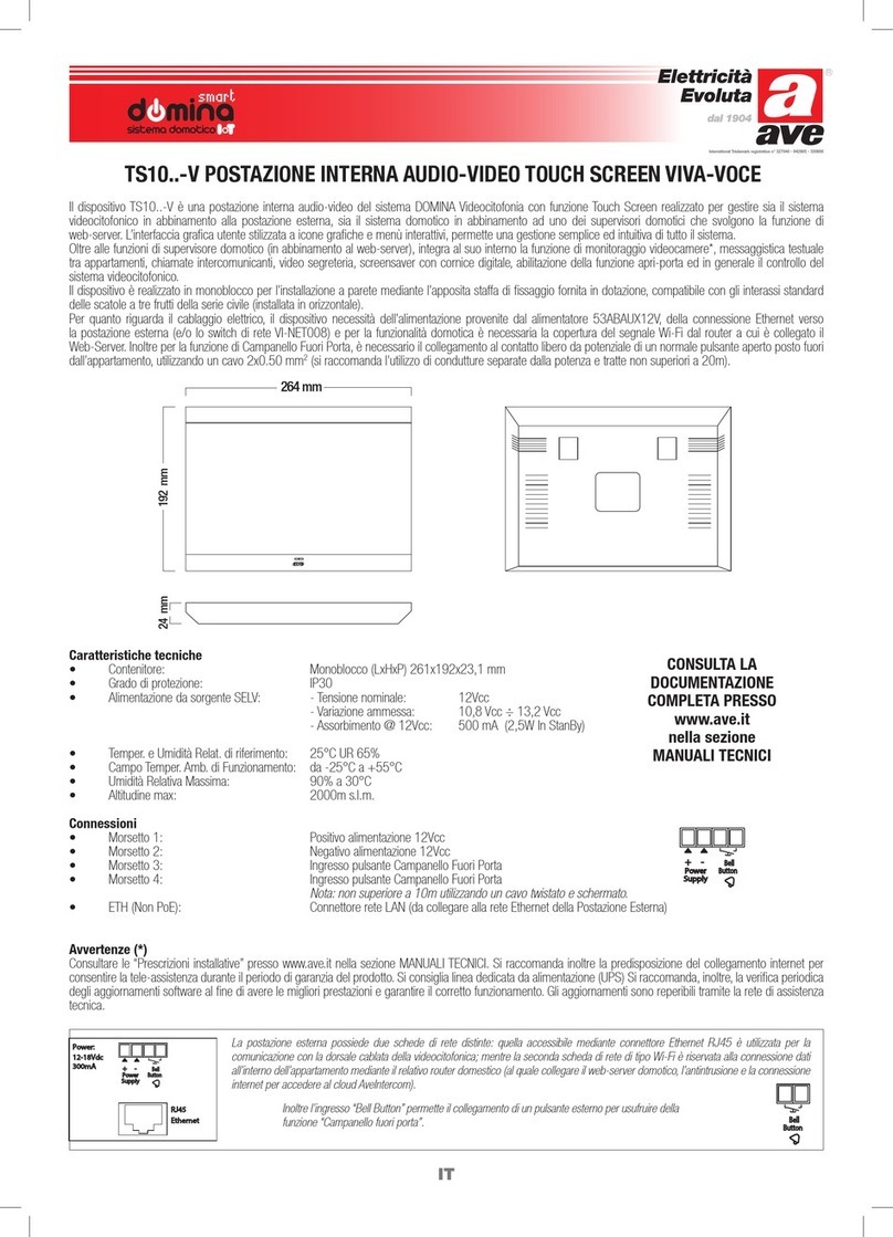
AVE smart domina VILLA User manual

International Trademark registration n° 327040 - 942905 - 330600
IT
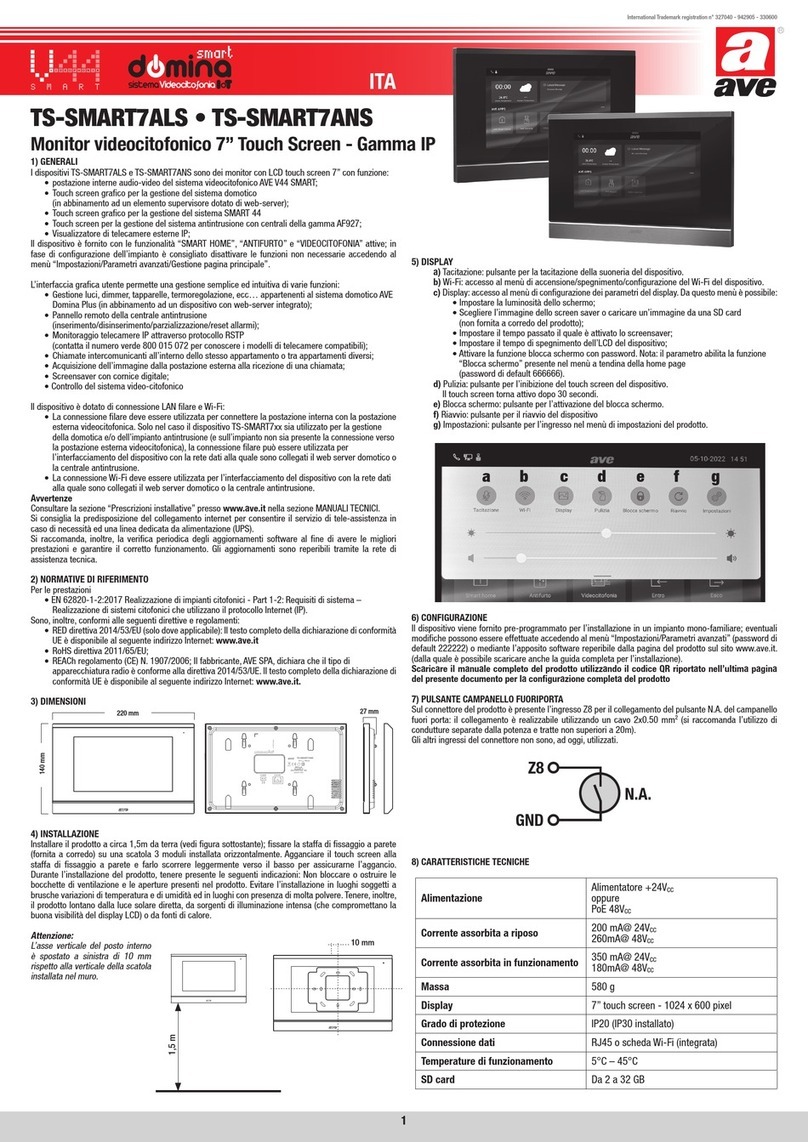
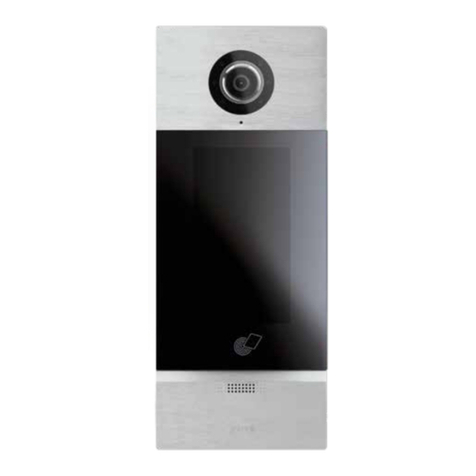
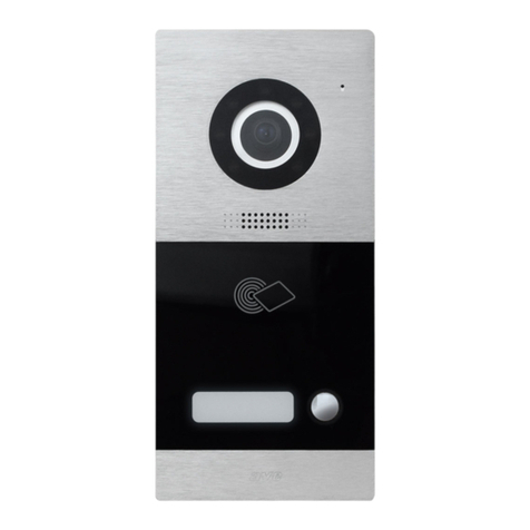
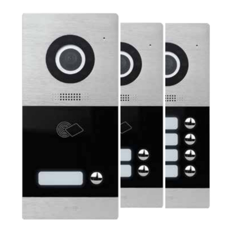
VI-AV002-TC POSTAZIONE ESTERNA AUDIO-VIDEO MODELLO “VILLA”
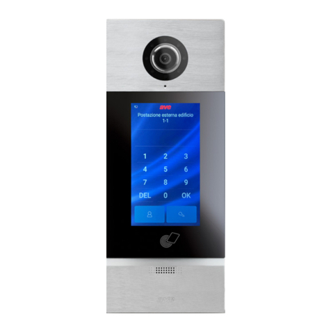
Il dispositivo VI-AV002-TC è la Postazione Esterna audio/video modello “Villa“ del sistema DOMINA Videocitofonia, è installabile da esterno parete o incasso mediante
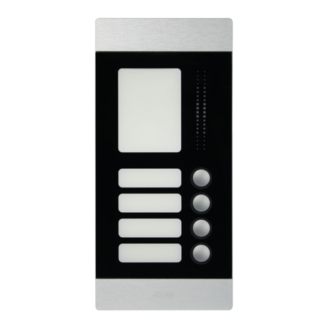
apposite scatole e parapioggia. Commercializzata con frontale a doppio tasto di chiamata (bifamiliare), è predisposta per la sostituzione del frontale al fine di ottenere
la versione monofamiliare o la versione quadrifamiliare modificandone la configurazione. La postazione esterna audio-video modello “VILLA“ si contraddistingue grazie
al design raffinato, moderno ed alla tecnologia “touch” mediante la quale si effettua la chiamata. Inoltre la retroilluminazione bianca e gli ampi cartellini porta nome
permettono la personalizzazione della stessa senza interferire con la praticità d’uso e l’eleganza stessa.
Le postazioni esterne del sistema videocitofonico adottano la tecnologia contactless MIFARE®garantendo affidabilità anche nella funzione accessoria di controllo
accessi. Il sistema sfrutta il codice univoco delle Card senza alcuna necessità di scrivere dati all’interno della stessa. Questo lascia la possibilità di utilizzare la medesima
card anche con i sistemi di terze parti (non forniti da AVE) permettendo di offrire ai clienti una gamma di servizi molto ampia, a cui si avrà accesso tramite la stessa
tessera di ingresso. Il sistema è in grado di gestire due tipologie di Card: Master e USER. La prima, quella Master, utilizzata per abbinare le 50 card di tipo User alla
postazione esterna. La seconda, quella User, per utilizzare la funzione controllo accessi con la possibilità di limitarne il funzionamento ad una fascia oraria diversa
per ogni giorno della settimana. Un registro eventi terrà lo storico degli accessi così da poter monitorare eventuali passaggi tessera e bloccarne quelli indesiderati.
Il dispositivo è realizzato in monoblocco per installazione a parete mediante l’apposita scatola con parapioggia VI-BOX102RP-TC, oppure per installazione da incasso
mediante l’apposita scatola VI-BOX002-TC e opzionalmente il tettuccio VI-RP002-TC.
110 mm 90 mm
220 mm
10 mm
40 mm
10 mm
12 mm
RJ45
Ethernet
+
12V Out.
500 mA
30V 500mA
Sensor
Door
Door Lock:
Input:
Button
Lock
GND
+
Power
NO NC C
PULSANTE DI
CONFIGURAZIONE
Permette l’accesso
al menu vocale di
configurazione e la
creazione della
Card MASTER.
110 mm 90 mm
220 mm
10 mm
40 mm
10 mm
12 mm
RJ45
Ethernet
+
12V Out.
500 mA
30V 500mA
Sensor
Door
Door Lock:
Input:
Button
Lock
GND
+
Power
NO NC C
+
GND
NO NC C
CONSULTA LA
DOCUMENTAZIONE
COMPLETA PRESSO
www.ave.it
nella sezione
MANUALI TECNICI
Per quanto riguarda il cablaggio elettrico, il dispositivo necessità dell’alimentazione provenite dal alimentatore 53ABAUX12V o in alternativa alla connessione Ethernet
di tipo PoE mediante opportuno PoE Iniector. Mentre per la gestione del varco pedonale, possiede direttamente a bordo dispositivo l’ingresso pulsante Apri Porta e
l’uscita a relè (C-NC-NA) con contatto libero da potenziale. Inoltre è disponibile l’uscita (12Vcc 500mA) per l’alimentazione dell’elettroserratura, sfruttabile soprattutto
nel caso in cui il dispositivo fosse alimentato mediante PoE. Per quanto riguarda la funzionalità del riconoscimento “Porta Aperta” è necessario il collegamento con il
contatto libero da potenziale di un normale sensore magnetico posto sul varco, utilizzando un cavo 2x0.50 mm2 (si raccomanda l’utilizzo di condutture separate dalla
potenza e tratte non superiori a 100m; da considerarsi porte di segnale secondo la norma EN 61000-6-1).
Caratteristiche tecniche
• Contenitore: Monoblocco (LxHxP) 110x220x56,5 mm
• Grado di protezione: IP54
• Videocamera: IP Camera 2Mpx con angolo di visione 80° in orizzontale e 55° in verticale
• Alimentazione da sorgente SELV: - Tensione nominale: 12Vcc / PoE
- Variazione ammessa: 10,8 Vcc ÷ 13,2 Vcc
- Assorbimento @ 12Vcc: 500 mA (2,5W In StanBy, 4W a pieno carico)
• Temper. e Umidità Relat. di riferimento: 25°C UR 65%
• Campo Temper. Amb. di Funzionamento: da -40°C a +70°C
• Umidità Relativa Massima: 90% a 30°C
• Altitudine max: 2000m s.l.m.
Connessioni
• Morsetto 1, 2 e 3: Door Sensor, Ingresso sensore Porta Aperta
GND
Lock Button, Ingresso pulsante Apri Porta
• Morsetto 4, 5 e 6: Door Lock, Contatto relè (NO Normalmente Aperto)
Door Lock, Contatto relè (NC Normalmente Chiuso)
COM Comune
• Morsetto P+ e P-: Power + / -, Positivo e Negativo alimentazione 12Vcc
(In alternativa al PoE)
• Morsetto 12V e G: 12V Out,
Linea 12Vcc 500mA per alimentazione elettroserratura
• ETH: Connettore rete LAN (da collegare alla rete Ethernet della Postazione Esterna)
RJ45RJ45
EthernetEthernet
500 mA500 mA
Door LDoor Locock:k:
Input:Input:
110 mm 90 mm
220 mm
10 mm
40 mm
10 mm
12 mm
++
GNDGND
NONO NCNC CC
1 6
2 5
3 4

IT
CONFIGURAZIONE
Il dispositivo viene fornito con la configurazione di default per un impianto bifamiliare ed è quindi Plug&Play, tuttavia può essere modificato accedendo al menù
di configurazione direttamente mediante la connessione ethernet ed un browser internet connesso all’indirizzo IP del dispositivo (per la configurazione consulta la
documentazione completa presso www.ave.it nella sezione MANUALI TECNICI).
Indirizzo IP di default: 10.10.10.82 Login: admin Password: password
Pagina web di configurazione
Video Intercom System (VI-AV002-TC)
Impostazione Parametri
Parametri di configurazione dell'Videocitofono Versione Kernel Versione Hardware Versione Software
MAC Address
Aggiorna Dispositivo Registro Carte Memorizzate Registro Carte Lette
Impostazioni Audio Impostazione Tempi
Impostazioni Lingua
Volume Della Suoneria
Volume Conversazione
Suoneria Abilita Sensore PortaAbilita Sensore Porta
Ritardo Allarme Porta-Aperta
Abilita Funzione Segreteria On / OffOn / Off
On / Off
Tempo di Risposta (5~115)s%
%(0~253)s
(1~300)s
Tempo Apertura Porta
Impostazioni di Rete Impostazioni Controllo Accessi
Indirizzo IP
Subnet mask
Gateway
ID Dispositivo ID Dispositivo Espansione Relè
Abilita Carta Master
On / Off
On / Off
On / Off
Abilita Carta Sorveglianza
Espansione Uscita Relè
Impostazioni Chiamate in Uscita
Chiamata 1:
Chiamata 3:
Chiamata 2:
Chiamata 4:
1
1
1
1
Id.
Id.
Id.
Id.
Indirizzo IP
Indirizzo IP
Indirizzo IP
Indirizzo IP
2
2
2
2
ID Dispositivo
ID Dispositivo
ID Dispositivo
ID Dispositivo
3
3
3
3
4
4
4
4
Fascia Oraria Abilitazione Carta Impostazioni Data e Ora
Domenica Porta Aperta
00 0000 00: :-
Lunedi Porta Aperta
00 0000 00: :-
Mercoledi Porta Aperta
00 0000 00: :-
Venerdi Porta Aperta
00 0000 00: :-
Martedi Porta Aperta
00 0000 00: :-
Giovedi Porta Aperta
00 0000 00: :-
Sabato Porta Aperta
00 0000 00: :-
(necessario per sincronizzare data e ora)
Impostazioni Data -
-
AAAA
HH
MM
MM
DD
SS
-
-
Impostazioni Ora
Indirizzo IP della Postazione Interna
Salva Data e Ora
ESCISALVA
S1S1
S4
S7
S3
S6
S5
S2

IT
RIPRISTINO CONFIGURAZIONE DI DEFAULT E MENU DI CONFIGURAZIONE VOCALE
Nel retro del dispositivo è presente un pulsante di configurazione che permette l’accesso al menu vocale contenente le seguenti funzioni (lo scorrimento e/o la
selezione di una di esse avviene mediante i pulsanti di chiamata frontali seguendo la voce guida):
• Registrazione Carta UTENTE, permette di memorizzare l’UID delle card identificate come UTENTE al fine di abilitarne la funzione Apri-Porta;
• Registrazione Carta MASTER, permette di memorizzare l’UID della card identificata come MASTER al fine di permettere il successivo accesso al menu senza
la pressione del pulsante di configurazione posto sul retro del dispositivo;
• Cancellazione Carte UTENTE, permette di eliminare tutte le Carte Utente;
• Ripristino Configurazione di Default ed eliminazione della Carta Master;
• Cambio lingua dei Messaggi Vocali, permette il cambio lingua Inglese/Italiano;
• Indirizzo IP del Dispositivo, riproduce un messaggio vocale contenente la configurazione di rete;
S1
S1 - IMPOSTAZIONI DI RETE
Contiene le impostazioni di rete del dispositivo e l’indirizzo ID del
sistema Videocitofonico utilizzato in abbinamento al cod.TS10. S2
S2 - IMPOSTAZIONI CONTROLLO ACCESSI
Abilita il lettore di card MIFARE per il Controllo accessi (in funzione
delle fasce orarie riportate S6) e la memorizzazione dei passaggi
della Sorveglianza. Inoltre permette di abilitare e associare il
relativo indirizzo fisico del Modulo Espansione Relè.
S7
S8 - IMPOSTAZIONI DATA E ORA
Consente di impostare data e ora del dispositivo e di specificare
l’indirizzo IP dell’unità interna con la quale sincronizzare l’orologio.
S6
S6 - FASCIA ORARIA ABILITAZIONE CARTA
Permette di limitare l’accesso mediante Card MIFARE, in funzione
delle Fasce orarie impostate.
S3
S3 - IMPOSTAZIONI AUDIO
Modifica la Lingua dei messaggi vocali, i volumi e la suoneria
utilizzata dal dispositivo per segnalare all’utente la chiamata in
corso con un’unità interna.
S4
S4 - IMPOSTAZIONI TEMPI
Abilita la funzione Segreteria, la lettura del Sensore Porta-Aperta e
contiene le impostazioni riguardanti i TIMER del sistema:
Tempo di Risposta, ritardo prima dell’intervento della Segreteria
(il tempo totale della chiamata è di 120” trascorso il quale la
chiamata viene chiusa notificandone la mancata risposta);
Tempo Apertura Porta, durata della chiusura del contatto ApriPorta;
Ritardo Allarme Porta-Aperta, tempo oltre il quale se l’ingresso
Sensore Porta rimane aperto viene notificato l’allarme (nel caso in
cui l’ingresso risulti aperto senza che sia sopraggiunto il comando
digitale Apri-Porta dal relativo pulsante o da un’Unità Interna,
l’allarme è istantaneo);
S5
S5 - IMPOSTAZIONI CHIAMATE IN USCITA
Contiene le impostazioni dei quattro Pulsanti di Chiamata,
ognuno dei quali richiede l’indirizzo ID associato alle Unità Interne
rispondenti alla medesima chiamata e i relativi quattro indirizzi IP.
Per unificare due o quattro pulsanti di chiamata inserire le
medesime configurazioni.
NO
ATTENZIONE: L’orario del dispositivo dipende dall’orologio dell’Unità Interna, la quale dovrà essere alimentata mediante Linea UPS.
INDIRIZZAMENTO
L’esempio sottostante rappresenta la configurazione quadrifamiliare, per realizzare la configurazione monofamiliare è sufficiente replicare i dati di CHIAMATA 1
su CHIAMATA 2/3/4, mentre per realizzare la configurazione bifamiliare sarà necessario replicare i dati di CHIAMATA 1 su CHIAMATA 2 e replicare quelli di
CHIAMATA 3 su CHIAMATA 4 (i dati dovranno essere congrui con le configurazioni delle postazioni interne).
INSTALLAZIONE
CHIAMATA 1 CHIAMATA 2
CHIAMATA 3 CHIAMATA 4
IP: 10.10.10.10
IP: 10.10.10.11
IP: 10.10.10.12
IP: 10.10.10.13
IP: 10.10.10.20
IP: 10.10.10.21
IP: 10.10.10.22
IP: 10.10.10.23
IP: 10.10.10.30
IP: 10.10.10.31
IP: 10.10.10.32
IP: 10.10.10.33
IP: 10.10.10.40
IP: 10.10.10.41
IP: 10.10.10.42
IP: 10.10.10.43
ID: 10 ID: 20
ID: 30 ID: 40
192 mm24 mm
264 mm
192 mm24 mm
264 mm
192 mm24 mm
264 mm
192 mm24 mm
264 mm
ID: 01
IP: 10.10.10.82
110 mm 90 mm
220 mm
10 mm
40 mm
10 mm
12 mm

IT
COLLEGAMENTI
CON ALIMENTATORE
COD. 53ABAUX12V
CON ALIMENTATORE
DA SWITCH POE
220 mm
12 mm
GND
NO NC C
+
+_
53ABAUX12V
12VDC
230Vac
LN
L
N
S
P
12 mm
GND
NO NC C
+
S
P
POE
Avvertenze installative: Utilizzare cavo costituito da idonea guaina esterna e 2 conduttori essibili intrecciati tra loro di sezione
0,50mmq. Lunghezza massima dall’alimentatore 100m.

GB
VI-AV002-TC VIDEO ENTRY SYSTEM OUTDOOR PANEL - “VILLA” MODEL
Device VI-AV002-TC is the “Villa” model of the outdoor panel for the DOMINA Video Entry system; it can be installed from outside the wall or flush mounted using
special boxes and rain guard. It is sold with front panel that has a double call button (two-family design); however, the front panel can be replaced to achieve a single-
family or four-family version by changing the configuration. The “video entry system outdoor panel — VILLA” model — stands out for its refined, modern design and
“touch-screen” technology used to make the call. Moreover, the white backlighting and wide name plates make it possible to customize the unit without sacrificing
any of its practicality and elegance.
The video entry system outdoor panels use contactless MIFARE®technology, thus ensuring reliability, even in the entry control accessory function. The system uses
the unique code for the Cards, no need to write any data to them. This means that the same card can even be used with third party systems (not supplied by AVE),
thus offering customers a very wide range of services that can be accessed through the same input card. The system can handle two types of Card: Master and
USER. The Master is used to pair up the 50 User-type cards to the outdoor panel. The User card serves to use the entrance control function which can, in turn, limit
operation to a different time slot for each day of the week. An event log stores the access history so all card passes can be monitored and any unwanted ones blocked.
This one-piece device is designed for wall installation with a special box VI-BOX102RP-TC with rain guard, or for recessed installation using the special box VI-
BOX002-TC and optional canopy VI-RP002-TC.
110 mm 90 mm
220 mm
10 mm
40 mm
10 mm
12 mm
RJ45
Ethernet
+
12V Out.
500 mA
30V 500mA
Sensor
Door
Door Lock:
Input:
Button
Lock
GND
+
Power
NO NC C
CONFIGURATION
BUTTON
Allows access to
vocal configuration
menu and creation
of the MASTER Card.
110 mm 90 mm
220 mm
10 mm
40 mm
10 mm
12 mm
RJ45
Ethernet
+
12V Out.
500 mA
30V 500mA
Sensor
Door
Door Lock:
Input:
Button
Lock
GND
+
Power
NO NC C
+
GND
NO NC C
SEE THE FULL
DOCUMENTATION
IN THE TECHNICAL
MANUALS SECTION
AT www.ave.it.
As regards the electrical wiring, the device requires power from the 53ABAUX12V power supply or, as an alternative, from a PoE-type connection to the Ethernet,
achieved with a suitable PoE Injector. Instead, to manage pedestrian entry, the Open Door button input and relay output (C-NC-NA) with potential-free contact are
located directly on the device. In addition, an output (12Vdc 500mA) is available to power the electric lock, used particularly when the device is powered by PoE.
As regards the “Open Door” recognition function, this requires connection to the potential-free contact of a normal magnetic sensor located at the doorway opening,
performed using a 2x0.50 mm2 cable (conductors separated from the power supply and which do not exceed 20m in length are recommended; these are to be
considered signal ports as per EN 61000-6-1).
Technical characteristics
• Container: One-piece device (LxHxD) 110x220x56.5 mm
• Protection rating: IP54
• Video camera: IP Camera 2Mpx with 80° horizontal and 55° vertical viewing angle
• Power supply from SELV source: - Rated voltage: 12Vdc / PoE
- Admissible variation: 10.8 Vdc – 13.2 Vdc
- Absorption @ 12Vdc: 500 mA (2.5W In Standby, 4W at full load)
• Reference Temper. and Rel. Humidity: 25°C RH 65%
• Operating Temperature Range: from -40°C to +70°C
• Maximum Relative Humidity: 90% at 30°C
• Max altitude: 2000m a.s.l.
Connections
• Clamp 1, 2 and 3: Door Sensor, Door Open Sensor Input
GND
Lock Button, Open Door Button Input
• Clamp 4, 5 and 6: Door Lock, Relay Contact (NO Normally Open)
Door Lock, Relay Contact (NC Normally Closed)
COM Common
• Clamp P+ and P-: Power + / -, Positive and Negative 12Vdc power supply
(As an alternative to PoE)
• Clamp 12V and G: 12V Out,
12Vdc 500mA line for electric lock power supply
• ETH: LAN network connector (to be connected to the Ethernet network of the Outdoor Station)
RJ45RJ45
EthernetEthernet
500 mA500 mA
Door LDoor Locock:k:
Input:Input:
110 mm 90 mm
220 mm
10 mm
40 mm
10 mm
12 mm
++
GNDGND
NONO NCNC CC
1 6
2 5
3 4
International Trademark registration no. 327040 - 942905 - 330600

GB
CONFIGURATION
When supplied, the default Plug&Play configuration is for a two-family system; however, this can be modified by accessing the configuration menu directly through
the Ethernet connection and an internet browser connected to the device IP address (for configuration, see the full documentation in the TECHNICAL MANUALS
section at www.ave.it).
Default IP address: 10.10.10.82 Login: admin Password: password
Configuration web page
Video Entry System (VI-AV002-TC)
Parameters Setting
Video Entry System configuration parameters Kernel Version Hardware Version Software Version
MAC Address
Update Device Cards Saved Register Cards Read Register
Audio Settings Time Setting
Language Settings
Ringtone Volume
Conversation Volume
Ringtone Enable Door SensorEnable Door Sensor
Door-Open Alarm Delay
Enable Answering Machine Function On / OffOn / Off
On / Off
Response Time (5~115)s%
%(0~253)s
(1~300)s
Door Opening Time
Network Settings Access Control Settings
IP address
Subnet mask
Gateway
Device ID Relay Expansion Device ID
Enable Master Card
On / Off
On / Off
On / Off
Enable Surveillance Card
Relay Expansion Output
Outgoing Call Settings
Call 1:
Call 3:
Call 2:
Call 4:
1
1
1
1
Id.
Id.
Id.
Id.
IP address
IP address
IP address
IP address
2
2
2
2
Device ID
Device ID
Device ID
Device ID
3
3
3
3
4
4
4
4
Card Enabled Time Slot Date and Time Settings
Sunday Door Opened
00 0000 00: :-
Monday Door Opened
00 0000 00: :-
Wednesday Door Opened
00 0000 00: :-
Friday Door Opened
00 0000 00: :-
Tuesday Door Opened
00 0000 00: :-
Thursday Door Opened
00 0000 00: :-
Saturday Door Opened
00 0000 00: :-
Date Settings -
-
YYYY
HH
MM
MM
DD
SS
-
-
Time settings
IP address of Indoor Panel
(required for date and time synchronization)
Save Date and Time
EXITSAVE
S1S1
S4
S7
S3
S6
S5
S2

GB
DEFAULT RESET CONFIGURATION AND VOCAL CONFIGURATION MENU
The back of the device has a configuration button used to access the vocal menu which offers the following functions (it is possible to scroll through and/or select
these functions using the front call buttons following the indications given under Help):
• USER Card Registration, used to save the UID for those cards identified as USERs so they can be enabled for the Open-Door function;
• MASTER Card Registration, used to save the UID of the card identified as MASTER so it can be enabled for subsequent access to the menu without having
to press the configuration button at the back of the device;
• Delete USER Cards, used to delete all User Cards;
• Reset Default Configuration and elimination of Master Card;
• Change language of Voice Messages, used to change between English/Italian;
• Device IP Address, plays back a voice message containing the network configuration;
S1
S1 - NETWORK SETTINGS
Contains the device network settings and ID address for the Video
Entry System used in combination with code TS10. S2
S2 - ENTRY CONTROL SETTINGS
Used to enable the MIFARE card reader to Control Entries
(according to the time slots reported in S6) and to store
Surveillance passes. It can also enable and associate the relative
physical address for the Relay Expansion Module.
S7
S8 - DATE AND TIME SETTINGS
Used to set device date and time and specify the IP address of the
indoor unit the clock is to be synchronized with.
S6
S6 - CARD ENABLED TIME SLOT
Used to restrict MIFARE Card access according to the time slots
set.
S3
S3 - AUDIO SETTINGS
Used to change the voice message language, volume and ring
tone used by the device to notify the user that a call is in progress
with an indoor unit.
S4
S4 - TIMES SETTINGS
Used to enable Answering Machine function, Door-Open Sensor
reading and contains the settings for the system TIMERS:
Response Time, delay before the answering machine kicks in
(total call time is 120 seconds, after which the call is closed and
a missed call reported);
Door Opening Time, length of time for closing the OpenDoor
contact;
Door-Open Alarm Delay, time after which an alarm is reported
if the Door Sensor input remains open (if no digital OpenDoor
command has been given using the relative button or by an Indoor
Unit, this alarm is instantaneous);
S5
S5 - OUTGOING CALL SETTINGS
Contains the settings for the four Call Buttons, each requiring the
ID address associated with the Indoor Units answering that call
and their four IP addresses.
To merge two or four Call Buttons, enter the same settings.
NO
WARNING: The time on the device depends on the clock on the Indoor Unit, which must be powered by a UPS Line.
ROUTING
The example below shows a four-family configuration. To create a single-family configuration, just repeat the data for CALL 1 also for CALLs 2, 3 and 4; instead,
to create a two-family configuration, the data for CALL 1 must be repeated for CALL 2 and the data for CALL 3 repeated for CALL 4 (the data must be consistent
with the configurations of the indoor panels).
INSTALLATION
CALL 1 CALL 2
CALL 3 CALL 4
IP: 10.10.10.10
IP: 10.10.10.11
IP: 10.10.10.12
IP: 10.10.10.13
IP: 10.10.10.20
IP: 10.10.10.21
IP: 10.10.10.22
IP: 10.10.10.23
IP: 10.10.10.30
IP: 10.10.10.31
IP: 10.10.10.32
IP: 10.10.10.33
IP: 10.10.10.40
IP: 10.10.10.41
IP: 10.10.10.42
IP: 10.10.10.43
ID: 10 ID: 20
ID: 30 ID: 40
192 mm24 mm
264 mm
192 mm24 mm
264 mm
192 mm24 mm
264 mm
192 mm24 mm
264 mm
ID: 01
IP: 10.10.10.82
110 mm 90 mm
220 mm
10 mm
40 mm
10 mm
12 mm

NOTE
Per la durata e le condizioni di garanzia dei singoli prodotti vedasi www.ave.it e il catalogo commercia-
le vigente.
I prodotti devono essere commercializzati in confezione originale, in caso contrario al rivenditore e/o
installatore è fatto obbligo di applicare e di trasmettere all’utilizzatore le istruzioni che accompagnano il
prodotto e/o pubblicate su www.ave.it e sul catalogo commerciale vigente.
I prodotti AVE sono prodotti da installazione. Vanno installati da personale qualificato secondo le norma-
tive vigenti e gli usi, rispettando le istruzioni di conservazione, d’uso e di installazione di AVE S.p.A.
Si richiede inoltre il rispetto delle condizioni generali di vendita, note, avvertenze generali, avvertenze
garanzie, reclami e avvertenze tecniche per l’installatore riportate su www.ave.it e sul catalogo com-
merciale vigente.
NOTES
For duration and warranty conditions regarding the single products, please visit www.ave.it and see
the current commercial catalogue.
Products shall be sold in the original packaging otherwise the dealer and/or installer has the obligation
to apply and submit the instructions provided alongside the product and/or published in www.ave.it
and on the current commercial catalogue to the user.
Ave products are installation products. They should be installed by skilled personnel in compliance with
the laws in force and uses, in accordance with the AVE S.pA. storage, use and maintenance instructions.
Installers are also required to meet the general sales conditions, notes, general warnings, warranty con-
ditions, claims and technical instructions indicated in www.ave.it and in the current commercial cata-
logue.
NOTES
Pour la durée et les conditions de garantie de chacun des produits, veuillez consulter le site www.ave.
it et le catalogue commercial en vigueur.
Les produits doivent commercialisés dans l’emballage d’origine. Dans le cas contraire, le revendeur et/
ou l’installateur sont obligés d’appliquer et de transmettre à l’utilisateur les instructions qui accompa-
gnent le produit et/ou qui sont publiées sur www.ave.it et sur le catalogue commercial en vigueur.
Les produits AVE sont des produits d’installation. Ils doivent être installés par des personnes qualifiées
conformément aux normes en vigueur et aux usages, en respectant les instructions de conservation,
d’utilisation et d’installation d’AVE S.p.A.
De plus, il faut que soient respectées les conditions générales de vente, les notes, les consignes
générales, les consignes sur la garantie, les réclamations et les consignes techniques pour l’installa-
teur indiquées sur le site www.ave.it et sur le catalogue commercial en vigueur.
NOTAS
Para obtener información sobre la duración y las condiciones de garantía de cada uno de los produc-
tos, consulte el sitio www.ave.it y el catálogo comercial vigente.
Los productos deben ser comercializados en su embalaje original; de lo contrario, el vendedor y/o
instalador deberá aplicar y transmitir al usuario las instrucciones que acompañan al producto y/o que
se encuentran publicadas en el sitio www.ave.it y en el catálogo comercial vigente.
Los productos AVE son artículos que requieren instalación. La misma debe ser efectuada por personal
cualificado, conforme a las normativas vigentes y a los usos, respetando las instrucciones de conser-
vación, uso e instalación establecidas por AVE S.p.A.
Asimismo, es necesario respetar las condiciones generales de venta, notas, advertencias generales o
de garantía, reclamos y advertencias técnicas para el instalador detalladas en el sitio www.ave.it y en
el catálogo comercial vigente.
International Trademark
registration n°
327040 - 942905 - 330600
PRIMA DI INSTALLARE SISTEMI E AUTOMATISMI È VIVAMENTE CONSIGLIABILE FREQUENTARE
UN CORSO DI FORMAZIONE, OLTRE LA LETTURA ATTENTA DELLE ISTRUZIONI
BEFORE INSTALLING ANY AUTOMATION SYSTEMS IT IS RECOMMENDED TO ATTEND A TRAINING
COURSE AND READ THE INSTRUCTIONS CAREFULLY.
AVANT D’INSTALLER SYSTÈMES ET APPAREILLAGES D’AUTOMATISATION, IL EST FORTEMENT
RECOMMANDÉ D’ASSISTER À UN COURS DE FORMATION ET DE LIRE ATTENTIVEMENT LES INSTRUCTIONS.
ANTES DE INSTALAR LOS SISTEMAS AUTOMATIZADOS ES MUY RECOMENDABLE ASISTIR A UN CURSO
DE FORMACIÓN, MÁS ALLÁ DE LA LECTURA CUIDADOSA DE LAS INSTRUCCIONES.
C0721 - 03 - 230920
Il fabbricante AVE S.p.a. dichiara sotto la propria responsabilità che i dispositivi descritti nel presente manuale sono conformi ai requisiti stabiliti dalla Direttiva 2014/53/UE (RED).
Il testo completo della dichiarazione di conformità UE è disponibile al seguente indirizzo www.ave.it
The manufacturer AVE S.p.a. declares, under its own responsibility, that the devices described in this manual comply with the requirements of the Radio Equipment Directive 2014/53/EU (RED).
The full text of the EU declaration of conformity is available at www.ave.it.
CONNECTIONS
WITH POWER SUPPLY
CODE 53ABAUX12V
WITH POWER SUPPLY
FROM POE SWITCH
220 mm
12 mm
GND
NO NC C
+
+_
53ABAUX12V
12VDC
230Vac
LN
L
N
S
P
12 mm
GND
NO NC C
+
S
P
POE
Warnings for installation: Use cable composed of a suitable outer sheath and 2 twisted exible conductors (conductor section:
0.50 mm2). Maximum length from power supply: 100m.
This manual suits for next models
1
Table of contents
Languages:
Other AVE Intercom System manuals

AVE
AVE DOMINA VI2F-PE7T User manual

AVE
AVE bitronvideo B-Twin DOMINAplus User manual

AVE
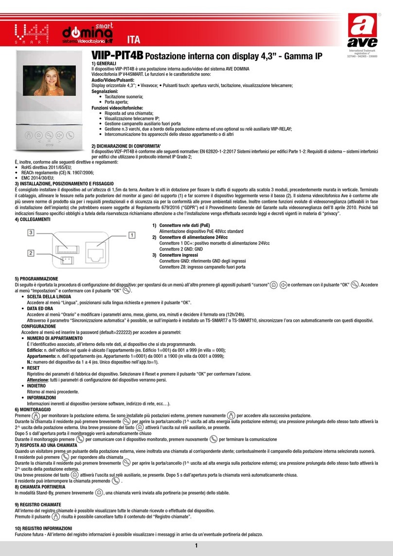
AVE DOMINA VIIP-PIT4B User manual

AVE
AVE Domus 100 SISTEMA44 User manual

AVE
AVE DOMINA TS10 V Series User manual

AVE
AVE domina smart TS-SMART7ALS User manual

AVE
AVE domina SMART V44 TS-SMART10 Series User manual

AVE
AVE V44 EASY User manual

AVE
AVE smart domina VIIP-PE1 User manual

AVE
AVE 45387C User manual