AVE smart domina VIIP-PE1 User manual

ITA
VIIP-PE1 - VIIP-PE2 - VIIP-PE4
Postazioni esterne videocitofoniche - Gamma IP
1) GENERALI
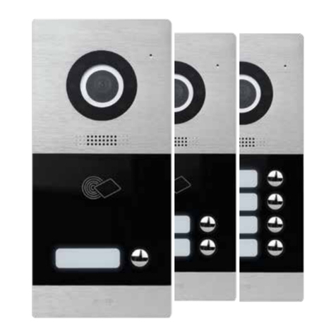
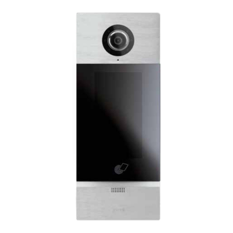
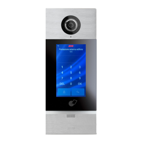
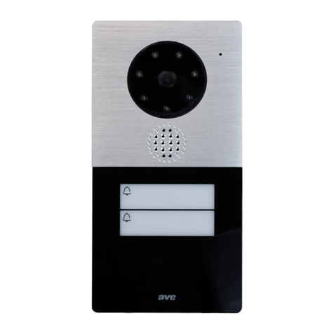
I dispositivi VIIP-PE1, VIIP-PE2 e VIIP-PE4 sono le Postazioni Esterne audio/video del sistema AVE DOMINA Videocitofonia IP V44 SMART. I
dispositivi sono realizzati in monoblocco per installazione a incasso mediante la scatola (art. VI-BOX3), la cornice di supporto (art.VI-BOX3C)
o l’eventuale tettuccio parapioggia (art. VI-RPBOX3) oppure ad appoggio parete mediante l’apposita scatola (art. VI-BOX4).
Le caratteristiche principali dei dispositivi sono:
• VIIP-PE1: versione monofamiliare ad un pulsante. Lettore di card MIFARE® integrato;
• VIIP-PE2: versione bifamiliare a due pulsanti. Lettore di card MIFARE® integrato;
• VIIP-PE4: versione quadrifamiliare a quattro pulsanti;
• Illuminazione cartellini con led bianco con intensità variabile in funzione della luminosità ambientale;
• Relè di apertura accesso in “potenza”;
• Relè di apertura accesso con contatto normalmente aperto;
Nota: nella versione quadrifamiliare non è integrato il lettore di card MIFARE®.
2) DICHIARAZIONE DI CONFORMITA’
I dispositivi VIIP-PE1, VIIP-PE2, VIIP-PE4 sono conformi alle seguenti normative:
• EN 62820-1-1:2016 Sistemi interfonici per edifici - Parte 1-1: Requisiti di sistema – Generale. Grado 2; Sono, inoltre, conformi alle
seguenti direttive e regolamenti:
• RED direttiva 2014/53/EU (solo dove applicabile): Il testo completo della dichiarazione di conformità UE è disponibile al seguente indirizzo
Internet: www.ave.it
Il fabbricante, AVE SPA, dichiara che il tipo di apparecchiatura radio è conforme alla direttiva 2014/53/UE.
Il testo completo della dichiarazione di
conformità UE è disponibile al seguente indirizzo Internet: www.ave.it.
• RoHS direttiva 2011/65/EU;
•
REACh regolamento (CE) N. 1907/2006;
3) INSTALLAZIONE, POSIZIONAMENTO E FISSAGGIO
Gli art. VIIP-PE1, VIIP-PE2, VIIP-PE4 possono essere installati all’esterno, nei limiti di temperatura indicati e seguendo le istruzioni riportate nel presente documento. L’altezza suggerita d’installazione
del prodotto è: limite superiore a 1,6 m da terra (vedere figura 1). Per installare i dispositivi fare riferimento alla figura 2. Prevedere l’installazione del prodotto in modo che la telecamera del dispositivo
non sia accecata da fonti luminose dirette (lampioni, fari o illuminazione solare diretta) che ne comprometterebbero il funzionamento.
Nota: in condizioni di scarsa luminosità ambientale, i dispositivi sono muniti di led bianchi per una corretta illuminazione del soggetto posizionato ad una distanza massima di 1m.
Il dispositivo può essere collegato alla pulsantiera ausiliaria a 8 pulsanti (art. VI-PEAUX) attraverso un connettore (3) posizionato sul retro del dispositivo. Il cavo di collegamento tra i due dispositivi è
fornito a corredo della pulsantiera ausiliaria (art. VI-PEAUX).
Il sistema videocitofonico Ave è conforme alle più severe norme di prodotto sia per i requisiti prestazionali e sicurezza sia per la conformità alle prove ambientali relative. Inoltre contiene funzioni
evolute di videosorveglianza (attivabili in fase di installazione dell’impianto) che potrebbero essere soggette al Regolamento 679/2016 (“GDPR”) ed il Provvedimento Generale del Garante sulla
videosorveglianza dell’8 aprile 2010. Poiché tali indicazioni fissano specifici obblighi a tutela della riservatezza richiamiamo attenzione a che l’installazione venga effettuata secondo leggi e decreti
vigenti in materia di “privacy”.
4) ACCESSO AI CARTELLINI PORTANOME
Per accedere ai cartellini portanome svitare la vite posta nella parte inferiore e sganciare il vetro. Effettuata la modifica reinserire il vetro e avvitare la vite precedentemente rimossa (vedere figura 3).
5) COLLEGAMENTI
Di seguito è riportato il significato dei morsetti di collegamento posti nella parte posteriore del dispositivo. La disposizione dei connettori è riportata in figura 4.
Morsetto 1: DOOR ingresso pulsante N.O. per apertura porta Morsetto 4: NO contatto normalmente aperto per apertura porta
Morsetto 2: GS ingresso sensore porta aperta Morsetto 5: EL uscita “alta energia” per apertura porta
Morsetto 3: NO contatto normalmente aperto per apertura porta Morsetto 6: GND riferimento per ingressi GS e DOOR e uscita EL
Extend (3): collegamento colonna ausiliaria (art. VI-PEAUX)
Connettore 2 poli dedicato alla connessione di un eventuale alimentatore +24VCC
Connettore RJ45 per la connessione della rete dati (con possibilità di alimentazione mediante switch PoE 48VCC).
6) INDIRIZZAMENTO
L’indirizzamento del dispositivo e del numero dell’interno associato ad ogni pulsante dello stesso, sono configurati mediante software di programmazione disponibile per PC con sistema operativo
Windows®. Per ulteriori informazioni consultare il manuale di programmazione del sistema IP V44 SMART. Il sistema IP consente l’installazione di un numero massimo di:
• 16 postazioni esterne in modalità “Building”
• 32 postazioni esterne in modalità “Villa”
Ogni postazione esterna può essere integrata con un numero massimo di 4 colonne ausiliarie a 8 chiamate (art. VI-PEAUX).
Le postazioni esterne devono essere indirizzate mediante l’apposito software di gestione del dispositivo.
7) IMPOSTAZIONE DEL VOLUME DELL’ALTOPARLANTE
Mediante software di programmazione disponibile per PC con sistema operativo Windows®. Per ulteriori informazioni consultare il manuale di programmazione del sistema IP V44 SMART.
8) IMPOSTAZIONE DEL TEMPO DI SBLOCCO DELLE ELETTROSERRATURE
I dispositivi consentono la regolazione del tempo di chiusura del relè di sblocco con contatto normalmente aperto (min 1 s – max 10 s) mediante software di programmazione disponibile per PC con
sistema operativo Windows®. Per ulteriori informazioni consultare il manuale di programmazione del sistema IP V44 SMART.
9) INGRESSO SENSORE PORTA APERTA (GS)
È possibile monitorare lo stato “Porta aperta” collegando un sensore normalmente aperto (es. AF902, AF903, ecc...) ai morsetti GND e GS. La rilevazione dello stato “Porta aperta” è automaticamente
abilitato quando l’ingresso GS è chiuso per un tempo superiore a 30 s; successivamente, se l’ingresso è lasciato aperto per più di 2 min, la postazione esterna emette una segnalazione acustica finché
l’ingresso non è nuovamente richiuso. Le postazioni interne emettono una segnalazione ottica (in funzione del modello) per segnalare l’allarme “Porta aperta”.
10) INGRESSO PULSANTE APRI-PORTA (DOOR)
Tra l’ingresso “DOOR” ed il morsetto GND può essere collegato un pulsante normalmente aperto (es. 441005): una breve pressione agisce sull’uscita del relè in potenza (EL).
11) PROGRAMMAZIONE DELLE CARD
Le postazioni esterne VIIP-PE1 e VIIP-PE2 hanno integrato un lettore di card MIFARE® che può essere gestito mediante le card art. 44339CHU-MB.
La procedura di programmazione delle card è riportata sul manuale completo del sistema IP V44 SMART disponibile sul sito www.ave.it.
12) RIPRISTINO DEI PARAMETRI DI DEFAULT
Per ripristinare i parametri di default del dispositivo seguire le istruzioni riportate nel manuale del dispositivo:
Nota: a seguito dell’operazione di reset è necessario ripetere la procedura di associazione delle card al dispositivo.
13) CARATTERISTICHE TECNICHE
Tensione massima di lavoro 24VCC con alimentatore ausiliario
48VCC mediante switch PoE N. max di dispositivi installabili 16 postazioni esterne in modalità “Building”
32 postazioni esterne in modalità “Villa”
Assorbimento in esercizio 250 mA max @24 VCC Telecamera CMOS con illuminatore a luce bianca
Assorbimento in stand-by 70 mA max @24 VCC Montaggio da appoggio parete o incasso
Assorbimento in esercizio 100 mA max @48 VCC PoE Grado di protezione IP20 (IP44 quando installato)
Assorbimento in stand-by 50 mA max @48 VCC PoE Classe ambientale secondo EN 62820-1-1 CLASSE IV
Dimensioni (L x H x P) 100 x 215 x 45,7 mm Sporgenza dal muro 10 mm
Temperatura di funzionamento Da -25°C a +55°C Attuatore #2 apertura porta Relè monostabile N.O. 1A/24VCC
Altitudine max. 2000 m s.l.m. N. max di card gestibili 200
PER SCARICARE IL MANUALE COMPLETO DEL SISTEMA IP SCANSIONA IL CODICE QR RIPORTATO NELLA PAGINA DEI DISEGNI
International Trademark
registration n°
327040 - 942905 - 330600

VIIP-PE1 - VIIP-PE2 - VIIP-PE4
Outdoor video-intercom stations - IP range
1) OVERVIEW
The VIIP-PE1,VIIP-PE2 and VIIP-PE4 are the outdoor audio/video stations of the AVE DOMINA IP V44 SMART Video-intercom range. It is a monobloc device for flush installation using the box (art.VI-BOX3),
the support frame (Art. VI-BOX3C) or the rain cover (Art. VI-RPBOX3), or for wall mounting by means of the appropriate box (art. VI-BOX4).
The main features of the devices are:
• VIIP-PE1: single-button one-call version. Integrated MIFARE® card reader;
• VIIP-PE2: two-button two-call version. Integrated MIFARE® card reader;
• VIIP-PE4: four-button four-call version;
• Name tags lighting with variable density white LEDs, depending on the brightness of the environment;
• Access opening relay with “powered” outlet;
• Access opening relay with normally open contact;
Note: The MIFARE® card reader is not integrated in the 4-button version.
2) DECLARATION OF CONFORMITY
VIIP-PE1, VIIP-PE2, VIIP-PE4 devices comply with the following standards:
• EN 62820-1-1:2016 Building intercom systems - Part 1-1: System Requirements – General. Grade 2; they also comply with the following directives and regulations:
• RED Directive 2014/53/EU (only where applicable): The full text of the EU declaration of conformity is available at the following address: www.ave.it
The manufacturer,AVE SPA, declares that the radio equipment complies with Directive 2014/53/EU.
The full text of the EU Declaration of Conformity is available at the following address: www.ave.it.
• RoHS Directive 2011/65/EU;
•
REACh Regulation (EC) No. 1907/2006;
3) INSTALLATION, POSITIONING AND FIXING
Items VIIP-PE1, VIIP-PE2, VIIP-PE4 can be installed outdoors, within the temperature limits indicated, and following the instructions in this document.The recommended installation height of the product
is: upper limit at 1.6 m from the ground (see figure 1). To install the devices, refer to figure 2. Install the product so that the camera of the device is not blinded by direct light sources (street lamps,
headlights or direct sunlight) that would compromise its operation.
Note: the devices are equipped with white LEDs that illuminate the subject positioned at a maximum distance of 1m in case of poor lighting.
The device can be connected to the auxiliary eight-button push-button panel (Art. VI-PEAUX) through a connector (3) located on the rear side of the device.The connection cable between the two devices
is supplied together with the auxiliary push-button panel (art. VI-PEAUX).
The AVE video-intercom system complies with the strictest product standards both as regards performance and safety requirements and compliance with the relevant environmental tests. It also
contains advanced video surveillance functions (which can be activated during installation of the system) that may be subject to Regulation 679/2016 (“GDPR”) and the General Provision of the Video
surveillance authority of 8 April 2010. Since these indications establish specific obligations for the protection of privacy, we draw attention to the fact that the installation is carried out according to
the current laws and legislative decrees on “privacy”.
4) ACCESS TO NAME TAGS
To access the name tags, unscrew the screw at the bottom and release the glass. Once the change has been made, reinsert the glass and tighten the previously removed screw (see figure 3).
5) CONNECTIONS
The meaning of the connection terminals located at the rear of the device is illustrated here below The arrangement of the connectors is shown in figure 4.
Terminal 1: DOOR N.O. button input for door opening Terminal 4: N.O. normally open contact for door opening
Terminal 2: GS door open sensor input Terminal 5: EL "high energy" output for door opening
Terminal 3: N.O. normally open contact for door opening Terminal 6: GND shared by GS and DOOR inputs and EL output
Extend (3): auxiliary tower connection (art. VI-PEAUX)
2-pin connector for connecting a possible +24 VDC power supply
RJ45 connector for data network connection (with power supply via 48 VDC PoE switch).
6) ADDRESSING
The addressing of the device and the extension number associated to each button of the same are configured by means of the programming software available for PCs with Windows® operating system.
Refer to the IP V44 SMART System Programming Manual for more information. The IP system allows the installation of up to:
• 16 outdoor stations in “Building” mode
• 32 outdoor stations in “Villa” mode
Each outdoor station can be integrated with up to four 8-call auxiliary towers (art. VI-PEAUX).
The outdoor stations must be addressed using the appropriate management software for the device.
7) SETTING THE LOUDSPEAKER VOLUME
Using programming software available for PCs with Windows® operating system. Refer to the IP V44 SMART System Programming Manual for more information.
8) SETTING THE UNLOCKING TIME OF THE ELECTRIC LOCKS
The devices allow adjusting the closing time of the normally open contact unlock relay (min 1 s – max 10 s) using the programming software available for PCs with Windows® operating system. Refer
to the IP V44 SMART System Programming Manual for more information.
9) DOOR OPEN SENSOR INPUT (GS)
The “Door open” status can be monitored by connecting a normally open sensor (e.g.AF902,AF903, etc...) to the GND and GS terminals.The “Door open” status detection is automatically enabled when
the GS input remains closed for more than 30 seconds; then, if the input is left open for more than 2 minutes, the outdoor station emits an acoustic signal until the input is closed again. The indoor
stations emit an optical signal (depending on the model) to warn of the “Door open” alarm.
10) DOOR OPENING BUTTON INPUT (DOOR)
A normally open button (e.g. 441005) can be connected between the “DOOR” input and the GND terminal: a short pressure acts on the output of the powered relay (EL).
11) PROGRAMMING OF CARDS
A MIFARE® card reader, which can be managed using the 44339CHU-MB card, is integrated in the VIIP-PE1 and VIIP-PE2 outdoor stations.
The card programming procedure can be found in the complete IP V44 SMART System manual available at www.ave.it.
12) RESETTING THE DEFAULT PARAMETERS
To reset the default parameters of the device, follow the instructions in the device manual:
Note: following the resetting operation, repeat the procedure for pairing the cards to the device.
13) TECHNICAL CHARACTERISTICS
Maximum operating voltage 24VDC with auxiliary power supply
48VDC via PoE switch Maximum number of devices that can be installed 16 outdoor stations in “Building” mode
32 outdoor stations in “Villa” mode
Absorption during operation 250 mA max @24 VCC Camera CMOS with white light illuminator
Absorption during stand-by 70 mA max @24 VCC Installation wall or flush installation
Absorption during operation 100 mA max @48 VCC PoE Protection rating IP20 (IP44 when installed)
Absorption during stand-by 50 mA max @48 VCC PoE Environmental class as per EN 62820-1-1 CLASS IV
Dimensions (L x H x D) 100 x 215 x 45.7 mm Protrusion from the wall 10 mm
Operating temperature From -25 °C to +55 °C Door opening actuator #2 N.O. monostable relay 1A/24VCC
Maximum altitude 2000 m a.s.l. Maximum number of cards that can be managed 200
TO DOWNLOAD THE COMPLETE MANUAL OF THE IP SYSTEM SCAN THE QR CODE SHOWN ON THE DRAWINGS PAGE
ENG

VIIP-PE1 - VIIP-PE2 - VIIP-PE4
Platines de rue pour visiophones - Gamme IP
1) GÉNÉRALITÉS
Les dispositifs VIIP-PE1, VIIP-PE2 et VIIP-PE4 sont les Platines de Rue audio/vidéo du système AVE DOMINA Visiophonie IP V44 SMART. Les dispositifs sont réalisés en monobloc pour une installation
à encastrement moyennant le boîtier (art. VI-BOX3), le cadre de support (art.VI-BOX3C) ou l’éventuelle visière pare-pluie (art. VI-RPBOX3) ou bien en saillie sur le mur moyennant le boîtier prévu à cet
effet (art. VI-BOX4).
Les caractéristiques principales des dispositifs sont les suivantes:
• VIIP-PE1: version pour une famille à un bouton. Lecteur de carte MIFARE® intégré;
• VIIP-PE2: version pour deux familles à deux boutons. Lecteur de carte MIFARE® intégré;
• VIIP-PE4: version pour quatre familles à quatre boutons;
• Éclairage des étiquettes par LED blanche, à intensité variable selon la luminosité environnante;
• Relais d’ouverture accès de «puissance»;
• Relais d’ouverture accès avec contact normalement ouvert;
Remarque: la version pour quatre familles n’intègre pas le lecteur de carte MIFARE®.
2) DÉCLARATION DE CONFORMITÉ
Les dispositifs VIIP-PE1, VIIP-PE2, VIIP-PE4 sont conformes à la norme ci-dessous:
• EN 62820-1-1:2016 Systèmes d’interphone de bâtiment - Partie 1-1: Exigences du système - Généralités. Degré 2; Ils sont en outre conformes aux directives et règlements suivants:
• Directive RED 2014/53/UE (uniquement si applicable): Le texte complet de la déclaration de conformité UE est disponible à l’adresse
Internet suivante: www.ave.it
Le fabricant, AVE SPA, déclare que le type d’équipement radio est conforme à la directive 2014/53/UE.
Le texte complet de la déclaration de conformité UE est disponible à l’adresse Internet suivante:
www.ave.it.
• Directive RoHS 2011/65/UE;
•
Règlement REACh (CE) N. 1907/2006;
3) INSTALLATION, PLACEMENT ET FIXATION
Les articles VIIP-PE1, VIIP-PE2, VIIP-PE4 peuvent être installés à l’extérieur, dans les limites de température indiquées et suivant les instructions contenues dans ce document. La hauteur d’installation
du produit suggérée est: limite supérieure à 1,6m du sol (voir figure 1). Pour l’installation des dispositifs, se référer à la figure 2. Prévoir l’installation du produit de façon à ce que la caméra du dispositif
ne soit pas aveuglée par des sources lumineuses directes (lampadaires, projecteurs ou éclairage direct du soleil) qui pourraient en compromettre le fonctionnement.
Remarque: en conditions de luminosité environnante insuffisante, les dispositifs sont équipés de LED blanches pour un éclairage correct du sujet placé à 1m au maximum.
Le dispositif peut être relié au clavier auxiliaire à 8 boutons (art.VI-PEAUX) par l’intermédiaire d’un connecteur (3) situé à l’arrière du dispositif. Le câble de connexion entre les deux dispositifs est fourni
avec le clavier auxiliaire (art. VI-PEAUX).
Le système de visiophonie Ave est conforme aux normes les plus sévères de produit, en ce qui concerne tant les exigences de prestations et de sécurité que la conformité aux tests environnementaux
relatifs. Il comprend en outre des fonctions évoluées de vidéosurveillance (à activer en phase d’installation du système) pouvant être soumises au Règlement 679/2016 («RGPD») et aux Dispositions
générales du Garant sur la vidéosurveillance du 8 avril 2010. Ces indications fixant des obligations précises de protection de la confidentialité, nous attirons l’attention sur le fait que l’installation est
réalisée conformément aux lois et décrets en vigueur en matière de «confidentialité».
4) ACCÈS AUX ÉTIQUETTES NOMINALES
Pour accéder aux étiquettes nominales, dévisser la vis située dans la partie inférieure et décrocher la vitre. Procéder à la modification, réinsérer la vitre puis visser la vis retirée précédemment (voir
figure 3).
5) BRANCHEMENTS
Ci-après, la signification des bornes de connexion situées à l’arrière du dispositif. La disposition des connecteurs est illustrée à la figure 4.
Borne 1: DOOR entrée bouton N.O. pour ouverture de la porte Borne 4: NO Contact normalement ouvert pour ouverture de la porte
Borne 2: GS entrée capteur de porte ouverte Borne 5: EL sortie «haute énergie» pour ouverture de la porte
Borne 3: NO Contact normalement ouvert pour ouverture de la porte Borne 6: GND référence pour entrées GS et DOOR et sortie EL
Extend (3): branchement colonne auxiliaire (art. VI-PEAUX)
Connecteur 2 pôles dédié à la connexion d’une éventuelle alimentation +24VCC
Connecteur RJ45 pour la connexion du réseau de données (avec possibilité d’alimentation par commutation PoE 48VCC).
6) ADRESSAGE
L’adressage du dispositif et du numéro d’appartement associé à chaque bouton de celui-ci, sont configurés au moyen du logiciel de programmation disponible pour PC avec système d’exploitation
Windows®. Pour de plus amples informations consulter le manuel de programmation du système IP V44 SMART. Le système IP permet l’installation d’un nombre maximum de:
• 16 platines de rue en mode “Building”
• 32 platines de rue en mode “Villa”
Chaque platine de rue peut être intégrée avec un nombre maximum de 4 colonnes auxiliaires à 8 appels (art. VI-PEAUX).
Les platines de rue doivent être adressées au moyen du logiciel de gestion du dispositif prévu à cet effet.
7) RÉGLAGE DU VOLUME DU HAUT-PARLEUR
Moyennant le logiciel de programmation disponible pour PC avec système d’exploitation Windows®. Pour de plus amples informations consulter le manuel de programmation du système IP V44 SMART.
8) RÉGLAGE DU TEMPS DE DÉVERROUILLAGE DES SERRURES ÉLECTRIQUES
Les dispositifs permettent le réglage du temps de fermeture du relais de déverrouillage avec contact normalement ouvert (min 1 s – max 10 s) moyennant le logiciel de programmation disponible pour
PC avec système d’exploitation Windows®. Pour de plus amples informations consulter le manuel de programmation du système IP V44 SMART.
9) ENTRÉE CAPTEUR DE PORTE OUVERTE (GS)
Il est possible de surveiller l’état «Porte ouverte» en branchant un capteur/détecteur normalement ouvert (p.ex. AF902, AF903, etc.) aux bornes GND et GS. La détection de l’état «Porte ouverte» est
automatiquement activée lorsque l’entrée GS est fermée pendant plus de 30s; ensuite, si l’entrée est laissée ouverte pendant plus de 2min, la platine de rue émet un signal sonore jusqu’à ce que
l’entrée ne soit de nouveau fermée. Les postes internes émettent un signal optique (en fonction du modèle) pour signaler l’alarme «Porte ouverte».
10) ENTRÉE BOUTON D’OUVERTURE DE LA PORTE (DOOR)
Entre l’entrée «DOOR» et la borne GND, on peut brancher un bouton normalement ouvert (p.ex. 441005): une brève pression agit sur la sortie du relais de puissance (EL).
11) PROGRAMMATION DES CARTES
Les platines de rue VIIP-PE1 et VIIP-PE2 ont un lecteur de carte MIFARE® intégré pouvant être géré au moyen des cartes art. 44339CHU-MB.
La procédure de programmation des cartes est fournie dans le manuel complet du système IP V44 SMART disponible sur le site www.ave.it.
12) RESTAURATION DES PARAMÈTRES PAR DÉFAUT
Pour restaurer les paramètres par défaut du dispositif suivre les instructions fournies dans le manuel du dispositif:
Remarque: au terme de la réinitialisation il est nécessaire de répéter la procédure d’association des cartes au dispositif.
13) CARACTÉRISTIQUES TECHNIQUES
Tension maximale de travail 24VCC avec alimentation auxiliaire
48VCC par commutation PoE Nombre max de dispositifs pouvant être installés 16 platines de rue en mode “Building”
32 platines de rue en mode “Villa”
Absorption de fonctionnement 250 mA max @24 VCC Caméra CMOS avec éclairage à lumière blanche
Absorption en veille 70 mA max @24 VCC Montage En saillie sur le mur ou à encastrement
Absorption de fonctionnement 100 mA max @48 VCC PoE Degré de protection IP20 (IP44 à l’installation)
Absorption en veille 50 mA max @48 VCC PoE Classe environnementale selon EN 62820-1-1 CLASSE IV
Dimensions (L x H x P) 100 x 215 x 45,7 mm Saillie du mur 10 mm
Température de fonctionnement De -25°C à +55°C Actionneur #2 ouverture porte Relais monostable N.O. 1A/24VCC
Altitude max. 2000m au-dessus du niveau de la mer Nombre max de cartes pouvant être gérées 200
POUR TÉLÉCHARGER LE MANUEL COMPLET DU SYSTÈME IP BALAYEZ LE CODE QR QUI FIGURE SUR LA PAGE DES DESSINS
F

S
VIIP-PE1 - VIIP-PE2 - VIIP-PE4
Puestos externos sistema de videoportero - Gama IP
1) GENERALES
Los dispositivos VIIP-PE1, VIIP-PE2 y VIIP-PE4 son los Puestos Externos audio/vídeo del sistema AVE DOMINA sistema de videoportero IP V44 SMART. Los dispositivos se realizan en monobloque para
instalación empotrado por medio de la caja (art. VI-BOX3), el marco de soporte (art.VI-BOX3C) o el eventual techo para lluvia (art.VI-RPBOX3) o con apoyo de pared por medio de la caja correspondiente
(art. VI-BOX4).
Las características principales de los dispositivos son:
• VIIP-PE1: versión monofamiliar de un botón. Lector de tarjeta MIFARE® integrado;
• VIIP-PE2: versión bifamiliar de dos botones. Lector de tarjeta MIFARE® integrado;
• VIIP-PE4: versión cuadrifamiliar de cuatro botones;
• Iluminación etiquetas con led blanco con intensidad variable en función de la luminosidad ambiental;
• Relé de apertura acceso en “potencia”;
• Relé de apertura acceso con contacto normalmente abierto;
Nota: en la versión de cuatro familias no está integrado el lector de tarjeta MIFARE®.
2) DECLARACIÓN DE CONFORMIDAD
Los dispositivos VIIP-PE1, VIIP-PE2, VIIP-PE4 están conformes con las siguientes normativas:
• EN 62820-1-1:2016 Sistemas de intercomunicación de edificios - Parte 1-1: Requisitos de sistema – General. Grado 2; además, son conformes a las siguientes directivas y reglamentos:
• Directiva RED 2014/53/EU (solo donde sea aplicable): El texto completo con la declaración de conformidad UE está disponible en la siguiente dirección
Internet: www.ave.it
El fabricante, AVE SPA, declara que el tipo de aparato de radio es conforme a la directiva 2014/53/UE.
El texto con declaración de conformidad UE está disponible en la siguiente dirección de Internet:
www.ave.it.
• Directiva RoHS 2011/65/EU;
•
REACh reglamento (CE) N. 1907/2006;
3) INSTALACIÓN, COLOCACIÓN Y FIJACIÓN
Los art. VIIP-PE1, VIIP-PE2, VIIP-PE4 pueden instalarse en el exterior, dentro de los límites de temperatura indicados y siguiendo las instrucciones señaladas en este documento. La altura de instalación
sugerida del producto es: límite superior a 1,6 m desde el suelo (observe la figura 1). Para instalar los dispositivos consulte la figura 2. Prevea la instalación del producto de modo que la cámara del
dispositivo no quede cegada por fuentes luminosas directas (farolas, faros o luz solar directa) que comprometerían el funcionamiento.
Nota: en condiciones de poca luz ambiental, los dispositivos están equipados con ledes blancos para una correcta iluminación del sujeto situado a una distancia máxima de 1m.
El dispositivo puede conectarse a la botonera auxiliar de 8 botones (art.VI-PEAUX) a través de un conector (3) colocado en la parte posterior del dispositivo. El cable de conexión entre los dos dispositivos
está proporcionado con la botonera auxiliar (art. VI-PEAUX).
El videoportero Ave cumple las más estrictas normas de producto tanto en lo que respecta a los requisitos de rendimiento y seguridad como en el cumplimiento de las pruebas ambientales pertinentes.
Además, contiene funciones avanzadas de videovigilancia (que pueden activarse durante la instalación del sistema) que podrían estar sujetas al Reglamento 2016/679 (“RGPD”) y a la Disposición
General del Garante sobre videovigilancia del 8 de abril de 2010. Dado que estas indicaciones establecen obligaciones específicas para proteger la confidencialidad, llamamos la atención a que la
instalación se efectúe de acuerdo con las leyes y decretos vigentes en materia de “privacidad”.
4) ACCESO A LAS ETIQUETAS PORTANOMBRE
Para acceder a las etiquetas portanombre desatornille el tornillo colocado en la parte inferior y desenganche el vidrio. Realizar la modificación introducir nuevamente el vidrio y atornillar el tornillo
anteriormente removida (ver la figura 3).
5) CONEXIONES
A continuación, se muestra el significado de los bornes de conexión colocados en la parte posterior del dispositivo. La disposición de los conectores está señalada en la figura 4.
Borne 1: DOOR entrada botón N.O. para apertura puerta Borne 4: NO contacto normalmente abierto para apertura puerta
Borne 2: GS entrada sensor puerta abierta Borne 5: EL salida “alta energía” para apertura puerta
Borne 3: NO contacto normalmente abierto para apertura puerta Borne 6: GND referencia para entradas GS y DOOR y salida EL
Extend (3): conexión columna auxiliar (art. VI-PEAUX)
Conector de 2 polos dedicado a la conexión de un eventual alimentador +24VCC
Conector RJ45 para la conexión de la red de datos (con posibilidad de alimentación por medio de switch PoE 48VCC).
6) DIRECCIÓN
El direccionamiento del dispositivo y del número del interior asociado a cada botón del mismo, están configurados por medio de software de programación disponible para ordenador de sistema
operativo Windows®. Para más información consulte con el manual de programación del sistema IP V44 SMART. El sistema IP permite la instalación de un número máximo de:
• 16 puestos externos en modalidad “Building”
• 32 puestos externos en modalidad “Villa”
Cada puesto externo puede estar integrado con un número máximo de 4 columnas auxiliares de 8 llamadas (art. VI-PEAUX).
Los puestos externos deben ser dirigidos por medio del software correspondientes de gestión del dispositivo.
7) CONFIGURACIÓN DEL VOLUMEN DEL ALTAVOZ
Por medio del software de programación disponible para ordenador con sistema operativo Windows®. Para más información consulte con el manual de programación del sistema IP V44 SMART.
8) CONFIGURACIÓN DEL TIEMPO DE DESBLOQUEO DE LAS ELECTRO CERRADURAS
Los dispositivos permiten la regulación del tiempo de cierre del relé de desbloqueo con contacto normalmente abierto (mín 1 s - máx 10 s) por medio del software de programación disponible para
ordenador con sistema operativo Windows®. Para más información consulte con el manual de programación del sistema IP V44 SMART.
9) ENTRADA SENSOR PUERTA ABIERTA (GS)
Es posible monitorizar el estado “Puerta abierta” conectando un sensor normalmente abierto (ej. AF902, AF903, etc...) a los bornes GND y GS. La detección del estado “Puerta abierta” está
automáticamente habilitada cuando la entrada GS está cerrada por un tiempo superior a 30 s; posteriormente, si la entrada está dejada abierta por más de 2 min, el puesto externo emite una señalación
acústica hasta que la entrada no esté nuevamente cerrada. Las estaciones interiores emiten una señal óptica (según el modelo) para señalar la alarma “Puerta abierta”.
10) ENTRADA BOTÓN ABRE-PUERTA (DOOR)
Entre la entrada “DOOR” y el borne GND puede conectarse un botón normalmente abierto (por ej. 441005): una breve presión actúa en la salida del relé en potencia (EL).
11) PROGRAMACIÓN DE LAS TARJETAS
Las estaciones exteriores VIIP-PE1 y VIIP-PE2 han integrado un lector de tarjeta MIFARE® que puede gestionarse mediante las tarjetas art. 44339CHU-MB.
El procedimiento de programación de las tarjetas se muestra en el manual con el sistema IP V44 SMART disponible en el sitio www.ave.it.
12) RESTABLECIMIENTO DE LOS PARÁMETROS POR DEFECTO
Para restablecer los parámetros por defecto del dispositivo seguir las instrucciones que figuran en el manual del dispositivo:
Nota: a continuación de la operación de reinicio es necesario repetir el procedimiento de asociación de la tarjeta al dispositivo.
13) CARACTERÍSTICAS TÉCNICAS
Tensión máxima de trabajo 24VCC con alimentador auxiliar
48VCC por medio de interruptor PoE N. máx de dispositivos instalables 16 puestos externos en modalidad “Building”
32 puestos externos en modalidad “Villa”
Absorción en ejercicio 250 mA máx @24 VCC Cámara CMOS con iluminador de luz blanca
Absorción en stand-by 70 mA máx @24 VCC Montaje con apoyo de pared o empotrado
Absorción en ejercicio 100 mA máx @48 VCC PoE Grado de protección IP20 (IP44 cuando instalado)
Absorción en stand-by 50 mA máx @48 VCC PoE Clase ambiental según EN 62820-1-1 CLASE IV
Dimensiones (L x H x P) 100 x 215 x 45,7 mm Saliente de la pared 10 mm
Temperatura de funcionamiento De -25°C a +55°C Actuador #2 apertura puerta Relé monoestable N.O. 1A/24VCC
Altitud máx. 2000m s.n.m. N. máx de tarjetas gestionables 200
PARA DESCARGAR EL MANUAL COMPLETO DEL SISTEMA IP ESCANEAR EL CÓDIGO QR QUE FIGURA EN LA PÁGINA DE LOS DIBUJOS

D
VIIP-PE1 - VIIP-PE2 - VIIP-PE4
Video-Türsprechanlage Außenstationen - IP-Serie
1) ALLGEMEINES
Die Geräte VIIP-PE1, VIIP-PE2 und VIIP-PE4 sind die Audio/Video-Außensprechstellen des AVE DOMINA Videophone IP V44 SMART-Systems. Die Geräte werden als eine Einheit für die Unterputz-
Installation unter Verwendung der Dose (Art. VI-BOX3), des Tragrahmens (Art. VI-BOX3C) oder des Regenschutzes (Art. VI-RPBOX3), falls erforderlich, oder für die Wandmontage unter Verwendung der
entsprechenden Dose (Art. VI-BOX4) hergestellt.
Die wichtigsten Gerätemerkmale im Überblick:
• VIIP-PE1: Ein-Familien-Version mit einer Taste. Integrierter MIFARE®-Kartenleser.
• VIIP-PE2: Zwei-Familien-Version mit zwei Tasten. Integrierter MIFARE®-Kartenleser.
• VIIP-PE4: Vier-Familien-Version mit vier Tasten.
• Namensschild-Beleuchtung mit weißer LED mit variabler Intensität je nach Umgebungslicht.
• Zugangs-Öffnungsrelais in „Leistung“.
• Zugangs-Öffnungsrelais mit Arbeitskontakt
Hinweis: Die Vier-Familien-Version verfügt nicht über einen integrierten MIFARE®-Kartenleser.
2) KONFORMITÄTSERKLÄRUNG
Die Geräte VIIP-PE1, VIIP-PE2 und VIIP-PE4 erfüllen die Anforderungen folgender Normen:
• EN 62820-1-1:2016 Gebäude-Sprechanlagen – Teil 1-1: Generelle Systemanforderungen. Grad 2; Sie entsprechen auch den folgenden Richtlinien und Verordnungen:
• RED-Richtlinie 2014/53/EU (nur wenn anwendbar): Der vollständige Text der EU-Konformitätserklärung ist abrufbar unter
Internet: www.ave.it
Der Hersteller,AVE SPA, erklärt, dass der Typ der Funkanlage der Richtlinie 2014/53/EU entspricht.
Der vollständige Text der EU-Konformitätserklärung ist abrufbar unter: www.ave.it
.
• RoHS-Richtlinie 2011/65/EU.
•
REACH-Verordnung (EG) Nr. 1907/2006;
3) INSTALLATION, POSITIONIERUNG UND BEFESTIGUNG
Die Geräte VIIP-PE1,VIIP-PE2 und VIIP-PE4 können innerhalb der angegebenen Temperaturgrenzen und unter Beachtung der in diesem Dokument enthaltenen Anweisungen im Freien installiert werden.
Die empfohlene Installationshöhe des Produkts beträgt: 1,6 m (oberer Abschluss) über dem Boden (siehe Abbildung 1). Zur Installation der Geräte siehe Abbildung 2. Installieren Sie das Produkt so, dass
die Videokamera des Geräts nicht durch direkte Lichtquellen (Straßenlaternen, Scheinwerfer oder direktes Sonnenlicht) geblendet wird, was ihre Funktion beeinträchtigen würde.
Hinweis: Für schlechte Umgebungslichtverhältnisse sind die Geräte mit weißen LEDs ausgestattet, die eine korrekte Ausleuchtung der Person in einer Entfernung von maximal 1 m ermöglichen.
Das Gerät kann über einen Anschluss (3) auf der Rückseite des Geräts an das 8-Tasten-Zusatztastenfeld (Art. VI-PEAUX) angeschlossen werden. Das Verbindungskabel zwischen den beiden Geräten ist
im Lieferumfang der Hilfshandbedienung (Art. VI-PEAUX) enthalten.
Das Ave-Video-Türsprechsystem wird nach den strengsten Produktnormen für Leistungs- und Sicherheitsanforderungen sowie unter Einhaltung einschlägiger Umweltvorschriften hergestellt. Es verfügt
außerdem über erweiterte Videoüberwachungsfunktionen (die bei der Installation der Anlage aktiviert werden können), die der Verordnung (EU) 2016/679 („DSGVO“) und der allgemeinen Bestimmungen
des Garanten in Bezug auf die Videoüberwachung vom 8. April 2010 unterliegen können. Da diese Leitlinien besondere Verpflichtungen zum Schutz der Privatsphäre enthalten, möchten wir Sie darauf
aufmerksam machen, dass die Installation gemäß den geltenden Datenschutzverordnungen und -gesetzen erfolgen muss.
4) ZUGANG ZU DEN NAMENSSCHILDERN
Um an die Namensschilder zu gelangen, lösen Sie die Schraube an der Unterseite und nehmen das Glas heraus. Danach setzen Sie das Glas wieder ein und ziehen die zuvor entfernte Schraube fest
(siehe Abbildung 3).
5) ANSCHLÜSSE
Die Bedeutung der Anschlussklemmen auf der Rückseite des Geräts ist unten dargestellt. Die Anordnung der Anschlüsse ist in Abbildung 4 dargestellt.
Klemme 1: DOOR Eingang Taste N.O. für die Türöffnung Klemme 4: NO Arbeitskontakt für die Türöffnung
Klemme 2: GS Eingang Tür-offen-Sensor Klemme 5: EL Ausgang „hohe Energie“ für die Türöffnung
Klemme 3: NO Arbeitskontakt für die Türöffnung Klemme 6: GND-Bezug für GS- und DOOR-Eingänge und EL-Ausgang
Extend (3): Anschluss einer Hilfssäule (Art. VI-PEAUX)
Dedizierter 2-poliger Anschluss für den Anschluss eines +24VDC-Netzteils, falls erforderlich
RJ45-Anschluss für den Anschluss an das Datennetz (mit Stromversorgung über 48VDC PoE-Switch).
6) ADRESSIERUNG
DieAdressierung des Geräts und die Nummer der Nebenstelle, die mit jederTaste des Geräts verbunden ist,werden mit einer Programmiersoftware konfiguriert, die für PCs mitWindows®-Betriebssystem
erhältlich ist. Weitere Informationen finden Sie im Programmierhandbuch des V44 SMART IP Systems. Das IP-System ermöglicht die Installation einer maximalen Anzahl von:
• 16 externen Stationen im Modus ‚Gebäude‘
• 32 externen Stationen im Modus ‚Villa‘
Jede Außenstation kann mit bis zu vier 8-Ruf-Hilfssäulen (Art. VI-PEAUX) integriert werden.
Externe Stationen müssen mit der entsprechenden Geräteverwaltungssoftware adressiert werden.
7) EINSTELLUNG DER LAUTSTÄRKE DES LAUTSPRECHERS
Mittels einer für PCs mit Windows®-Betriebssystem erhältlichen Programmiersoftware. Weitere Informationen finden Sie im Programmierhandbuch des V44 SMART IP Systems.
8) EINSTELLUNG DER ENTRIEGELUNGSZEIT DER ELEKTRISCHEN SCHLÖSSER
Die Geräte ermöglichen die Einstellung der Schließzeit des Entriegelungsrelais mit üblicherweise geöffnetem Kontakt (min. 1 s - max. 10 s) über eine für PCs mit Windows®-Betriebssystem erhältliche
Programmiersoftware. Weitere Informationen finden Sie im Programmierhandbuch des V44 SMART IP Systems.
9) EINGANG TÜR-OFFEN-SENSOR (GS)
Der Zustand „Tür offen“ kann durch Anschluss eines Arbeitskontakt-Sensors (z.B. AF902, AF903, etc.) an die Klemmen GND und GS überwacht werden. Die Erkennung des Zustands „Tür offen“ wird
automatisch aktiviert, wenn der Eingang GS länger als 30 s geschlossen ist. Wird der Eingang anschließend länger als 2 min offen gelassen, gibt die Außenstation ein akustisches Signal ab, bis der
Eingang wieder geschlossen wird. Die Innenstationen geben ein optisches Signal (modellabhängig) ab, um den Alarm „Tür offen“ zu signalisieren.
10) EINGANG TÜRÖFFNUNGSTASTE (DOOR)
Zwischen dem Eingang „DOOR“ und der Klemme GND kann eine Arbeitskontakt-Taste (z.B. 441005) angeschlossen werden: Ein kurzes Drücken schaltet den Relaisausgang in Leistung (EL).
11) KARTENPROGRAMMIERUNG
Die Außenstationen VIIP-PE1 und VIIP-PE2 verfügen über einen integrierten MIFARE®-Kartenleser, der mit den Karten Art. 44339CHU-MB verwaltet werden kann.
Das Verfahren zur Kartenprogrammierung ist im vollständigen Handbuch für das V44 SMART IP System zu finden, das unter www.ave.it verfügbar ist.
12) WIEDERHERSTELLEN DER STANDARDPARAMETER
Um das Gerät auf die Standardparameter zurückzusetzen, folgen Sie den Anweisungen im Handbuch des Geräts:
Hinweis: Nach dem Reset muss das Verfahren zur Zuordnung der Karten zum Gerät wiederholt werden.
13) TECHNISCHE MERKMALE
Maximale Betriebsspannung 24VDC mit Hilfsstromversorgung
48VDC über PoE-Switch Max. Anzahl der installierbaren Geräte 16 externe Stationen im Modus 'Gebäude'
32 externe Stationen im Modus 'Villa'
Betriebsstromaufnahme 250 mA max @24 VDC Videokamera CMOS mit Weißlicht-Beleuchtung
Stromaufnahme im Standby-Betrieb 70 mA max @24 VDC Montage Aufputz oder Unterputz
Betriebsstromaufnahme 100 mA max @48 VDC PoE Schutzart IP20 (IP44 wenn installiert)
Stromaufnahme im Standby-Betrieb 50 mA max @48 VDC PoE Umweltklasse nach EN 62820-1-1 KLASSE IV
Abmessungen (L x H x T) 100 x 215 x 45,7 mm Vorsprung von der Wand 10 mm
Betriebstemperatur Von -25 °C bis +55 °C Aktor #2 Türöffnung Monostabiles Relais N.O. 1A/24VCC
Max. Höhe 2000m s.l.m. Max. Anzahl der verwaltbaren Karten 200
ZUM HERUNTERLADEN DES VOLLSTÄNDIGEN IP-SYSTEMHANDBUCHS SCANNEN SIE DEN QR-CODE AUF DER SEITE DER ZEICHNUNGEN

AR
VIIP-PE1 - VIIP-PE2 - VIIP-PE4
IP -
(1
IP V44 SMART
AVE DOMINA / VIIP-PE4 VIIP-PE2 VIIP-PE1
(VI-BOX4 )
(VI-RPBOX3 ) (VI-BOX3C ) (VI-BOX3 )
MIFARE® VIIP-PE1 •
MIFARE®
VIIP-PE2 •
VIIP-PE4 •
•
“ ”
•
•
MIFARE®
(2
VIIP-PE1, VIIP-PE2, VIIP-PE4
2 –
-
EN 62820-1-12016 •
www.ave.it
( ) 2014/53/EU •
www.ave.it
2014/53/UE
AVE SPA
2011/65/EU •
1907/2006 (
) •
(3
1,6
VIIP-PE4 VIIP-PE2 VIIP-PE1
)
2 (1 )
(
1
(VI-PEAUX)
(3)(VI-PEAUX)8
)
Ave
2010 8 (« ») 679/2016
(
«»
(4
(3 )
(5
4
1 DOOR4 NO
2 GS5 “ ” EL
3 NO6 EL DOOR GS
GND
(VI-PEAUX )
(3) Extend
+24 2
( 48 PoE ) RJ45
(6
Windows®
IP IP V44 SMART
“Building”
16 •
“Villa”
32 •
(VI-PEAUX ) 8 4
(7
IP V44 SMART
Windows®
(8
Windows®
(
10
- 1
)
IP V44 SMART
(GS) (9
« » GS GND ( AF902 AF903 ) « »
30 GS
« » ( )
(DOOR) - (10
(EL)
(441005 ) GND «DORR»
(11
44339CHU-MB MIFARE® VIIP-PE2 VIIP-PE1
www.ave.it
IP V44 SMART
(12
(13
24
PoE 48
“Building”
16
“Villa”
32 24@
250
CMOS
24@
70
PoE 48@
100 (
IP44) IP20
PoE 48@
50EN 62820-1-1
45,7 × 215 × 100 ( x x )
10
°55+ °25- #2 24/
1
2000 200
IP

Mario Rossi
NO
160cm
3
3.1 3.2 3.3 3.4
2
14
VITI - SCREWS - VIS
TORNILLOS -
SCHRAUBEN -
TX+
TX-
RX+
RX-
+
-
GND
+24V
EXTEND
1 2 3 4 5 6
Manuale completo sistema IP • Complete manual for IP • Manuel complet système IP • Manual dotado de sistema de IP • Vollständiges handbuch IP-system
VIIP-PE1 VIIP-PE2 VIIP-PE4

NOTES
Pour la durée et les conditions de garantie de chacun des produits, veuillez consulter le site www.ave.it et le catalogue commercial en vigueur. Les produits doivent commercialisés dans l’emballage d’origine. Dans le
cas contraire, le revendeur et/ou l’installateur sont obligés d’appliquer et de transmettre à l’utilisateur les instructions qui accompagnent le produit et/ou qui sont publiées sur www.ave.it et sur le catalogue commercial
en vigueur. Les produits AVE sont des produits d’installation. Ils doivent être installés par des personnes qualifiées conformément aux normes en vigueur et aux usages, en respectant les instructions de conservation,
d’utilisation et d’installation d’AVE S.p.A. De plus, il faut que soient respectées les conditions générales de vente, les notes, les consignes générales, les consignes sur la garantie, les réclamations et les consignes
techniques pour l’installateur indiquées sur le site www.ave.it et sur le catalogue commercial en vigueur.
MISES EN GARDE: Les produits doivent être manipulés avec soin et stockés dans leur emballage d’origine dans un lieu sec, à l’abri des agents atmosphériques et à une température adaptée au stockage, conformément
aux indications fournies dans le manuel du produit. Si les produits sont dépourvus de leur emballage d’origine, il appartient au revendeur et/ou à l’installateur d’appliquer et de transmettre à l’utilisateur les instructions
d’utilisation qui accompagnent le produit. Il est déconseillé de stocker les produits pendant plus de 5 ans. Après l’ouverture de l’emballage, il convient de vérifier l’intégrité du produit. L’installation doit être effectuée par
du personnel qualifié, conformément aux dispositions de la réglementation en vigueur pour les systèmes électriques.
AVANT D’INSTALLER SYSTÈMES ET APPAREILLAGES D’AUTOMATISATION, IL EST FORTEMENT RECOMMANDÉ D’ASSISTER À UN COURS DE FORMATION ET DE LIRE
ATTENTIVEMENT LES INSTRUCTIONS.
NOTE
Para obtener información sobre la duración y las condiciones de garantía de cada uno de los productos, consulte el sitio www.ave.it y el catálogo comercial vigente. Los productos deben ser comercializados en su
embalaje original; de lo contrario, el vendedor y/o instalador deberá aplicar y transmitir al usuario las instrucciones que acompañan al producto y/o que se encuentran publicadas en el sitio www.ave.it y en el catálogo
comercial vigente. Los productos AVE son artículos que requieren instalación. La misma debe ser efectuada por personal cualificado, conforme a las normativas vigentes y a los usos, respetando las instrucciones de
conservación, uso e instalación establecidas por AVE S.p.A. Asimismo, es necesario respetar las condiciones generales de venta, notas, advertencias generales o de garantía, reclamos y advertencias técnicas para el
instalador detalladas en el sitio www.ave.it y en el catálogo comercial vigente.
ADVERTENCIAS: Los productos deberán manejarse con atención y almacenarse en su embalaje original en un lugar seco, resguardado de los agentes atmosféricos y a una temperatura adecuada para el
almacenamiento, tal como se indica en el manual del producto. En caso de que los productos no estén en su embalaje original, se exigirá al revendedor o al instalador que apliquen y transmitan al usuario las
instrucciones de uso que acompañan al producto. Se recomienda no almacenar productos por más de 5 años. Tras abrir el embalaje, asegurarse de que el producto esté intacto. La instalación deberá ser realizada por
personal cualificado, de acuerdo con las disposiciones de la normativa vigente para los equipos eléctricos.
ANTES DE INSTALAR SISTEMAS Y AUTOMATISMOS, ES MUY RECOMENDABLE ASISTIR A UN CURSO DE FORMACIÓN, ASÍ COMO LEER ATENTAMENTE LAS INSTRUCCIONES.
NOTES
For duration and warranty conditions regarding the single products, please visit www.ave.it and see the current commercial catalogue. Products shall be sold in the original packaging otherwise the dealer and/or installer
has the obligation to apply and submit the instructions provided alongside the product and/or published in www.ave.it and on the current commercial catalogue to the user. Ave products are installation products. They
should be installed by skilled personnel in compliance with the laws in force and uses, in accordance with the AVE S.p.A. storage, use and maintenance instructions. Installers are also required to meet the general sales
conditions, notes, general warnings, warranty conditions, claims and technical instructions indicated in www.ave.it and in the current commercial catalogue.
WARNINGS: The products must be handled with care and stored in their original packaging in a dry place, protected from the weather and at a suitable storage temperature as specified in the product manual. If the
products are not in their original packaging, the retailer and/or installer is required to apply the instructions for usage accompanying the product and pass them on to the user. Keeping products in stock for more than 5
years is not recommended. After opening the package, check that the product is intact. Installation must be performed by qualified personnel in compliance with current regulations regarding electrical installations.
BEFORE INSTALLING ANY AUTOMATION SYSTEMS, IT IS RECOMMENDED TO ATTEND A TRAINING COURSE AND READ THE INSTRUCTIONS CAREFULLY.
NOTE
Per la durata e le condizioni di garanzia dei singoli prodotti vedasi www.ave.it e il catalogo commerciale vigente. I prodotti devono essere commercializzati in confezione originale, in caso contrario al rivenditore e/o
installatore è fatto obbligo di applicare e di trasmettere all’utilizzatore le istruzioni che accompagnano il prodotto e/o pubblicate su www.ave.it e sul catalogo commerciale vigente. I prodotti AVE sono prodotti da
installazione. Vanno installati da personale qualificato secondo le normative vigenti e gli usi, rispettando le istruzioni di conservazione, d’uso e di installazione di AVE S.p.A. Si richiede inoltre il rispetto delle condizioni
generali di vendita, note, avvertenze generali, avvertenze garanzie, reclami e avvertenze tecniche per l’installatore riportate su www.ave.it e sul catalogo commerciale vigente.
AVVERTENZE: I prodotti devono essere maneggiati con cura e immagazzinati in confezione originale in luogo asciutto, al riparo dagli agenti atmosferici e ad una temperatura idonea allo stoccaggio come dà indicazioni
riportate sul manuale di prodotto. Qualora i prodotti non siano in confezione originale, è fatto obbligo al rivenditore e/o all’installatore di applicare e di trasmettere all'utilizzatore le istruzioni d'uso che accompagnano il pro-
dotto. Si consiglia di non tenere a magazzino prodotti per un periodo superiore a 5 anni Dopo aver aperto l'imballaggio, assicurarsi dell'integrità del prodotto. L’installazione deve essere effettuata da personale qualificato,
secondo le prescrizioni della norma vigente per gli impianti elettrici.
PRIMA DI INSTALLARE SISTEMI E AUTOMATISMI È VIVAMENTE CONSIGLIABILE FREQUENTARE UN CORSO DI FORMAZIONE, OLTRE LA LETTURA ATTENTA DELLE ISTRUZIONI
www.ave.it
www.ave.it / /
AVE S.P.A AVE
www.ave.it
ANMERKUNGEN
Die Garantiezeiten und -bedingungen der einzelnen Produkte sind unter www.ave.it und im geltenden Verkaufskatalog zu finden. Die Produkte müssen in Originalverpackung vermarktet werden; andernfalls ist der
Händler bzw. Installateur verpflichtet, die Anleitung, die dem Produkt beiliegt bzw. unter www.ave.it und im geltenden Verkaufskatalog veröffentlicht ist, anzuwenden und an den Endkunden weiterzugeben. Die Produkte
von AVE sind Installationsprodukte. Sie müssen durch Fachpersonal gemäß den geltenden Vorschriften und dem Anwendungszweck installiert werden, wobei die Lagerungs-, Bedienungs- und Installationsanweisungen von
AVE S.p.A. einzuhalten sind. Zu beachten sind außerdem die allgemeinen Geschäftsbedingungen, Anmerkungen, allgemeinen Warnhinweise, Garantie- und Reklamationshinweise und technischen Hinweise für den
Installateur, die unter www.ave.it und im geltenden Verkaufskatalog zu finden sind.
WARNHINWEISE: Die Produkte sind sorgfältig zu handhaben und in Originalverpackung trocken und wettergeschützt bei einer für die Lagerung geeigneten Temperatur gemäß den Anweisungen im Produkthandbuch zu
lagern. Sollten sich die Produkte nicht in der Originalverpackung befinden, ist der Händler bzw. Installateur verpflichtet, die Bedienungsanleitung, die dem Produkt beiliegt, anzuwenden und an den Endkunden weiterzuge-
ben. Es wird empfohlen, Produkte nicht länger als 5 Jahre im Lager zu halten. Nach dem Öffnen der Verpackung ist das Produkt auf Unversehrtheit zu prüfen. Die Installation muss durch Fachpersonal gemäß den gelten-
den Vorschriften für elektrische Anlagen erfolgen.
ES WIRD DRINGEND EMPFOHLEN, VOR DEM INSTALLIEREN VON AUTOMATIONSSYSTEMEN EINEN ENTSPRECHENDEN LEHRGANG ZU ABSOLVIEREN SOWIE DIE ANLEITUNG
AUFMERKSAM ZU LESEN.
www.ave.it
800 015 072
International Trademark
registration n°
327040 - 942905 - 330600
C0794 - 00 - 191022
This manual suits for next models
2
Table of contents
Languages:
Other AVE Intercom System manuals

AVE
AVE DOMINA VI2F-PIT4B User manual

AVE
AVE DOMINA VI2F-PE7T User manual

AVE
AVE Domina Smart VIIP-PE7T User manual

AVE
AVE DOMINA TS10 V Series User manual

AVE
AVE V44 EASY User manual

AVE
AVE smart domina VILLA User manual

AVE
AVE 45387C User manual

AVE
AVE domina SMART V44 TS-SMART10 Series User manual

AVE
AVE DOMINA Smart VI2F-PE1 User manual

AVE
AVE domina smart TS-SMART7ALS User manual