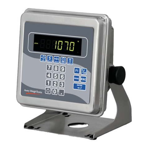
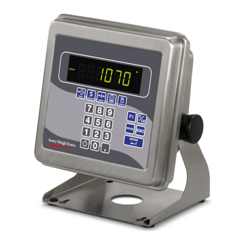
Avery Weigh-Tronix E1010 User manual

ServiceManual
Model E1010 Indicator
E1010
ENGLISH
AWT35-500132 Issue B April 23, 2007
*AWT35-500132*

2Model E1010 Indicator Service Manual
CAUTION
CAUTION: DANGER OF EXPLOSION IF BATTERY IS INCORRECTLY REPLACED.
REPLACE ONLY WITH THE SAME OR EQUIVALENT TYPE RECOMMENDED BY THE MANUFACTURER.
DISPOSEOFUSEDBATTERIESACCORDINGTOTHEMANUFACTURER’SINSTRUCTIONS
ATTENTION: IL Y A DANGER D’EXPLOSION S’IL Y A REMPLACEMENT INCORRECT DE LA BATTERIE,
REMPLACER UNIQUEMENT AVEC UNE BATTERIE DU MÊME TYPE OU D’UN TYPE ÉQUIVALENT
RECOMMANDÉ PAR LE CONSTRUCTEUR. METTRE AU REBUT LES BATTERIES USAGÉES
CONFORMÉMENTAUXINSTRUCTIONSDUFABRICANT”.
CAUTION: THE POWER SUPPLY CORD IS USED AS THE MAIN DISCONNECT DEVICE, ENSURE THAT THE
SOCKET-OUTLET IS LOCATED/INSTALLED NEAR THE EQUIPMENT AND IS EASILY ACCESSIBLE.
ATTENTION: LE CORDON D’ALIMENTATION EST UTILISÉ COMME INTERRUPTEUR GÉNÉRAL. LA PRISE DE
COURANT DOIT ÊTRE SITUÉE OU INSTALLÉE À PROXIMITÉ DE L’ÉQUIPEMENT ET ÊTRE FACILE D’ACCÉS”.
EUROPEAN COUNTRIES
WARNING
This is a Class A product. In a domestic environment this product may cause radio
interference in which the user may be required to take adequate measures.
UNITED STATES
This equipment has been tested and found to comply with the limits for
a Class A digital device, pursuant to Part 15 of the FCC Rules. These
limits are designed to provide reasonable protection against harmful
interference when the equipment is operated in a commercial environ-
ment. This equipment generates, uses, and can radiate radio frequency
energy and, if not installed and used in accordance with the instruction
manual, may cause harmful interference to radio communications.
Operation of this equipment in a residential area is likely to cause harmful
interference in which case the user will be required to correct the
interference at his own expense.
CANADA
This digital apparatus does not exceed the Class A limits for radio noise
emissions from digital apparatus set out in the Radio Interference
Regulations of the Canadian Department of Communications.
Le présent appareil numérique n'émet pas de bruits radioélectriques
dépassant les limites applicables aux appareils numériques de la
Class A prescrites dans le Règlement sur le brouillage radioélectrique
que edicté par le ministère de2s Communications du Canada.
E1010_rev2006_s.P65

3
Model E1010 Indicator Service Manual
Table of Contents
Specifications ................................................................................................................................ 3
Introduction ................................................................................................................................... 5
Front Panel ................................................................................................................................... 5
Keys ................................................................................................................................... 6
BatteryInformation ......................................................................................................................... 7
Error Messages ............................................................................................................................. 8
Accessing the Menus .............................................................................................................9
User Menu .............................................................................................................................10
ServiceMenu ................................................................................................................................13
CAL submenu ..................................................................................................................13
SCALE submenu .............................................................................................................16
APP submenu ..................................................................................................................23
Extra Info: Print Format Editing ..............................................................................................27
SERIALsubmenu.............................................................................................................31
TESTsubmenu ................................................................................................................36
AUDITsubmenu ...............................................................................................................39
INPUTsubmenu ...............................................................................................................40
OUTPUTsubmenu ...........................................................................................................41
SupervisorMenu ....................................................................................................................43
DATE submenu (Set date) ...............................................................................................44
HOUR submenu (Set time) ...............................................................................................44
SETUP submenu (Setup menu) .......................................................................................45
TEST submenu (Test menu) ............................................................................................51
AUDIT submenu (Audit counters) ..................................................................................... 53
SLEEP submenu (Sleep mode) .......................................................................................53
Appendix 1: Complete Menus .......................................................................................................54
ServiceMenu .........................................................................................................................54
SupervisorMenu ....................................................................................................................55
User Menu .............................................................................................................................55
Appendix 2: Connections and Communications ............................................................................56
Common Serial Port Connections ..........................................................................................56
External Inputs / Cutoffs (Trips) Connector .............................................................................56
TechnicalIllustrations....................................................................................................................57

4Model E1010 Indicator Service Manual
Specifications
Power requirements
• 100-240 Volts AC @ 600 mA
• 50/60 Hz
• Optional Internal battery: 23 hours of continuous
operation with one weight sensor; 15 hours of
continuous operation with four weight sensors
• Standby mode extends battery life
Excitation
• 5 volts
• Supports up to four 350-ohm weight sensors
Analog signal input range
• 12 mV/V
Analogsignalsensitivity
• 0.5 μV/division minimum
Calibration
• 2 to 5 points stored
Operational keys
• Tare, Select, Zero, Print, Units, F1, Clear, Mode,
Escape, Enter, On/Off, 0-9 numeric and decimal
point
Operational annunciators
• Center of Zero, Motion, Gross, Tare, Net, Battery
status
• Under/Target/Over
• Units of measure (LB, KG, Custom)
• Peak, Print, OP1, OP2, OP3, Count
Display
• Seven-digit, seven-segment, 0. 8-inch high
• Lighted STN Transmissive
• Display rate Selectable (1, 2, 5, 10)
Analog to digital conversion rate
• 60 times per second
Unit of measure:
• Three, independently programmable
• Pounds, Kilograms, Custom
Capacity selections
• 999,999 with decimal located from zero to five
places
Incremental selections
• Multiples and sub-multiples of 1, 2, 5
Programmable selections
• Zero range, motion detection, automatic zero
tracking, five-point linearization
Time and date / RAM
• Battery backed up real time clock and RAM
Internal resolution
• 64,424,509 counts per mV/V per sec
Standard inputs
• Three logic level inputs for: Zero, Print, Tare,
Units, F1
Standard outputs
• Three cutoff outputs, open collector design
• Two serial ports with RS-232. One of the ports can
also be 20mA current loop, or RS-422 or RS-485
Serialoutputs
Two serial ports:
• RS-232 / RS-422 / RS-485 / 20mA current loop
• RS-232
Serial Command Inputs
• Programmable serial response to ASCII character
input, SMA protocol, broadcast, enquire, RD-4100,
E-Series remote display
Selfdiagnostics
Display, keys, inputs, outputs, serial port,
Circuitry protection
• RFI, EMI, and ESD protection
Options
• Trips Interface Unit (TIU3)
Operating applications
• General weighing, simple counting, checkweighing,
accumulation, peak measurement, batching, and
remote display
Operating temperature
• 14 to 104° F (-10 to 40° C) approved
• -4 to 140° F (-20 to 60° C) non-legal
• 10 to 90% noncondensing humidity
Enclosure
• Stainless steel NEMA 6/4X
Dimensions:
• 9.25” W x 9.25” H x4.5 “ D
(23.5cm W x 23.5cm H x 11.4cm D)
(without mounting bracket)
• 9.75" W x 11” H x 7" D
(24.8cm W x 28cm H x 17.8cm D)
(with mounting bracket)
Weight: 11 lb, 5 kg
Agencies:
• NTEP CC# 04-029
Class III/IIIL:10,000 divisions
• OIML Cert. No. R76/1992-GB1-04.09
Class III: 10,000 divisions
• Canadian Weights and Measures pending
• UL/CUL
• CE marked

5
Model E1010 Indicator Service Manual
Introduction
About This Manual This manual covers the information you need to configure and service your
Model E1010 Indicator.
Major sections of this manual are headed by titles in a black bar like Intro-
duction above. Subheadings appear in the left column. Instructions and text
appear on the right side of the page. Occasionally notes, tips, and special
instructions appear in the left column.
Front Panel
The front panel, shown in Figure 1, consists of the keys and display.
Figure 1
E1010 front panel
The Model E1010 is battery
powered. The unit can be run
on AC power if the battery is
drained or absent.
See Battery Information for
more specific information.

6Model E1010 Indicator Service Manual
Keys The functions of the keys on the front panel are listed below.
Never press a key with any-
thing but your finger. Damage
to the overlay may result if
sharp or rough objects are
used.
Press the TARE key to perform a tare function. Also acts as a
left arrow key when in the menu structure.
Press the SELECT key to toggle between Gross, Tare, Net,
Count, Gross Accumulator, Net Accumulator, Transaction
Counter, Piece Weight, and Peak. This is dependent on the
current application. Also acts as an up arrow key when in the
menu structure. Press and hold to access the outputs function.
Press the ZERO key to zero the display.
Press the PRINT key to send information to a peripheral device
through one of the communication ports. Also acts as a down
arrow key when in the menu structure.
Press the UNITS key to scroll through the available units of
measure while in normal operating mode. Also acts as a right
arrow key when in the menu structure.
Press the F1 key to select application specific choices. Also
used to access PLU (Product Look Up) memory channels.
Press the C/CE key to clear entries.
Press the MODE key to scroll through the enabled applications.
The application name is briefly displayed when key is released.
Press the ESC key to escape a function or return to normal
operation mode. Press and hold to access the password
display for the menu structure.
Press the ENTER key to accept displayed choices.

7
Model E1010 Indicator Service Manual
Battery Information
This unit contains a sealed rechargeable 6 volt, 3.0Ah, lead-acid battery. Life
expectancy of this battery is 3-5 years in standby use or:
180 charging cycles (approx.) if discharged 100%
400 charging cycles (approx.) if discharged 50%
1200 charging cycles (approx.) if discharged 30%
Battery life is 23 hours with one 350 ohm weight sensor and 15 hours with
four 350 ohm weight sensors. Recharge time from complete discharge is 14
hours while powered up and in service (single loadcell). The AC adapter/
charger will charge the battery as it powers the indicator.
Risk of explosion if battery is
replaced by an incorrect type.
Dispose of used batteries
according to the
manufacturer’sinstructions.
Use the numeric keypad to enter values.
For example:
• ID entry
• Output target entry
• Preset tare entry
• Password entry
To turn the unit on, press and hold the ON/OFF key until the
backlight turns on. To turn the unit off, press and hold the ON/
OFF key until the unit turns off.

8Model E1010 Indicator Service Manual
Error Messages
The following are displays you may see if problems occur or if invalid opera-
tions are attempted with your indicator:
Display Description
Overrangeweight.
Underrangeweight.
The unit cannot perform a function. Displayed only
while key is held down.
Displayed while a key is pressed when attempting to
modify a sealed selection without edit privileges.
Appears when the A to D converter is not functioning
properly.
The indicator is being set to North American de-
faults.
The indicator is being set to European defaults.
Clearing calibration and resetting to factory default.
Wiping all configuration and calibration information
from the EEPROM. See note at left.
If you are in the counting sample mode menus, this
means the piece weight is too small, make the
sample size larger.
If the init-EE message is
displayed(canbedisplayedfor
over a minute), it is usually
followedbythe init-nA and
then the init-CL message.

9
Model E1010 Indicator Service Manual
Menu Structure
There are several menus you use to setup or service the Model E1010. You
access the menus through the front panel. Each menu is briefly described
here. For in depth information about a menu, go to that menu's section in
this manual.
Usermenu(passwordis111)
The first menu covered in this manual is the User menu. This
menu allows the user to:
• view software part numbers and revision level
• test the display and buttons
• test the serial port
• view the number of configurations and calibrations per-
formed on the indicator
Service menu (password is 0101)
The second menu covered is the Service menu. This menu
covers many areas. In it you can:
• calibrate the system
• configure the metrological function of the indicator
• Enable or disable available applications
• configure serial port
• test the display and buttons, test the serial port, test the
inputs and outputs (See note at left)
• view the number of configurations and calibrations performed
on the indicator
• configure inputs and outputs
Supervisor menu (password is 1793)
The third menu is the Supervisor menu. This section lets you:
• Set time and date
• Setup a piece look up (PLU) database, clear and/or print
data gathered by each application
• test the display and buttons, test the serial port, test the
inputs and outputs
• view the number of configurations and calibrations per-
formed on the indicator
1. Access the menus by pressing and holding the ESC key for 3-5 sec-
onds.
PASS_ is displayed.
2. Key in the password of the menu you want to access and press ENTER.
The first item in that menu is displayed.
3. Use the navigation keys shown in the box near each menu to move
through the menu.
Accessing the Menus
You must key in the password
within 10 seconds or the
display returns to normal
operation mode.
When testing inputs and
outputs, follow all lockout and
tagoutprocedurestoavoid
injuries.

10 Model E1010 Indicator Service Manual
User Menu The User menu lets you test various functions of the indicator. The User
menu is shown in Figure 2.
Figure 2
User menu flowchart
Following are specific instructions for the User menu.
1. Access the User menu by pressing and holding the ESC key for 3-5
seconds.
PASS_ is displayed.
2. Key in the User menu password (111) and press ENTER.
TEST is displayed.
3. Press the PRINT key.
ABOUT is displayed.
4. Press the PRINT key. . .
The part number and revision level of the software found in your
indicator is displayed. Use the TARE and UNITS keys to scroll
through the part number and revision.
5. Press the SELECT key. . .
ABOUT is displayed.
6. Press the UNITS key. . .
DISP is displayed. This is the display test item.
7. Press the PRINT key to perform a dynamic test of the display. . .
All the display elements flash.
8. Press the SELECT key to stop the test. . .
DISP is displayed.
9. Press the UNITS key. . .
BUTTON is displayed. This is the button test item.

11
Model E1010 Indicator Service Manual
10. Press the PRINT key to perform a button test. Each key you press will
be reflected on the display by a number to confirm the button is function-
ing correctly. See Table 1. The ESC key is excluded from this test. It is
used to stop the testing and return to the menu item.
Table 1
KEY= DISPLAY
TARE=tArE
SELECT=SELECt
ZERO=ZEro
PRINT =Print
UNITS =Units
F1 =F1
Power =on/oFF
9 =999
8= 888
7= 777
6 =666
5 =555
4 =444
3 =333
2 =222
1 =111
0 =000
. =dP
C/CE= CE
MODE= nnodE
ENTER=EntEr
ESC ESc is briefly displayed before exiting the test
11. Press ESC key to stop the button test.
BUTTONis displayed.
12. Press the UNITS key. . .
SERIAL is displayed. This is the serial test item. To test the serial
port, jumper the TX and RX lines (pins 2 & 3 in the DB-9 connec-
tor). See illustration at left.
13. Press the PRINT key to access the serial test.
The display will show PASS if the serial port is working properly
and the Rx and Tx lines are jumpered. If there is a problem the
display will show FAIL.
14. Press the SELECT key to exit the serial test.
SERIALis displayed. Remove the jumper from the TX and RX lines
of the DB-9 serial connector.
15. Press the SELECT key. . .
TEST is displayed.
User Menu (continued)

12 Model E1010 Indicator Service Manual
16. Press the UNITS key. . .
AUDIT is displayed.
17. Press the PRINT key. . .
CFG is displayed. This stands for the configuration audit counter.
Press the PRINT key to see the number of times the configuration
has been altered on this indicator. This number is displayed
temporarily and then CFG is displayed.
18. Press the SELECT key to return to the AUDIT menu item. Press the
UNITS key. . .
CAL is displayed. This stands for the calibration audit counter.
Press the PRINT key to see the number of times the indicator has
been calibrated. This number is displayed temporarily and then
CAL is displayed.
19. Press ESC twice to return to normal operation mode.

13
Model E1010 Indicator Service Manual
Service Menu The first level of the Service menu is shown in Figure 3. Under these nine
items you can do most of the configuration and calibration procedures to
ready the indicator for use. Other items are covered in the Supervisor menu
covered later in this manual
Figure 3
Service menu top level flowchart
Since the whole Service menu is quite large, it has been broken up into its
individual submenus. Each submenu is illustrated below followed by specific
instructions. See Appendix 1: Complete Service Menu to see the whole
menu at once.
Figure 4
CAL submenu
1. Access the Service menu. . .
CAL is displayed.
2. Press the PRINT key. . .
ZERO is displayed. Use this item to set the zero reference for the
indicator/scale.
3. Remove all weight from the scale and press the PRINT key. . .
Live weight is shown.
4. Press the ENTER key to perform the zero procedure. . .
BUSY is briefly displayed then the live weight which should be 0.
5. Press the ENTER key to save and return to the ZERO menu item. . .
ZERO is displayed.
Password for the Service menu
is 0101.
CAL submenu
ZERO
(Setting Zero Reference Point)
See Appendix 1 to see the
complete Service menu.
Press the ESC key to abort
calibration.
The indicator must be unsealed
to perform calibration. The
indicatorisunsealedwhen
Jumper JP1 is on. It is sealed
withJumperJP1removed.
Jumper JP1 must be in place
to unseal the indicator.

14 Model E1010 Indicator Service Manual
1. Press the UNITS key. . .
SPAN is displayed. Use this item to set the span for the indicator/
scale.
2. Press the PRINT key. . .
Current capacity is displayed.
3. Key in a new span weight value and press ENTER (when you start to
key in the span weight, the old value is replaced by the new)
or
press ENTER to accept current span weight value. . .
The live weight is displayed.
4. Place the correct span weight on the scale and press ENTER when
weight is stable.
BUSY is briefly displayed then the weight.
5. Press the ENTER key to accept the calibration and return to the SPAN
menu item. . .
SPAN is displayed.
6. Press ESCto return to normal weighing mode
OR go to step 1 below.
1. Press the UNITS key. . .
LINEAR is displayed. Use this item to set extra calibration points.
2. Press the PRINT key. . .
2 is displayed. This represents cal point 2.
3. Press the PRINT key to set this calibration point. . .
A numeric value is displayed.
4. Key in a weight value for this calibration point and press the ENTER
key. . .
Live weight on the scale is displayed.
5. Place the test weight for this calibration on the scale and press
ENTER. . .
Busy is briefly displayed and then 2.
6. Press the UNITS key to move to the next calibration point. . .
3is displayed.
LINEAR
(Linearization)
SPAN
(Setting Span)
Press the ESC key to abort
calibration.
Linear points must be done in
order (2-4) with increasing
weight.
Service Menu—CAL submenu (continued)

15
Model E1010 Indicator Service Manual
7. Repeat steps 3-6 for cal point 3 and 4.
When you are done 4will be displayed.
8. Press the SELECT key to return to the LINEAR menu item.
9. Press the ESC key to return to normal operating mode.
Use this item to view the live weight on the scale without exiting the Service
menu.
1. Press the UNITS key. . .
DISP is displayed.
2. Press the PRINT key. . .
The live weight is displayed.
3. Press the ENTER key to return to DISP.
4. Press the SELECT key. . .
CAL is displayed.
This completes the CAL section of the Service menu.
DISP
(Live Weight Display)
Service Menu—CAL submenu (continued)

16 Model E1010 Indicator Service Manual
SCALE submenu This section of the Service menu lets you set up the metrological items for
the scale and indicator. Figure 5 shows the flowchart of this menu item.
Follow the directions and explanations below to set up these items.
Figure 5
Scale submenu flowchart
1. Access the Service menu. . .
CAL is displayed.
2. Press the UNITS key. . .
SCALE is displayed.
3. Press the PRINT key. . .
CAP. is displayed. Use this item to set the capacity for the scale.
4. Press the PRINT key. . .
The current capacity value is shown.
5. Press ENTER to accept this value or key in a new capacity and press
ENTER. . .
CAP. is displayed.
CAP.
(Capacity)

17
Model E1010 Indicator Service Manual
DIV.
(Division)
DP.POS.
(Decimal point position)
UNITS
(Unit of measure)
Combine this item and the next one, DP.POS., to set the division size.
1. Press the UNITS key. . .
DIV. is displayed. This stands for the division size of your displayed
weight.
2. Press the PRINT key. . .
The current division size is shown. Pick from the following values;
1, 2, 5, 10, 20, 50, 1/2, 2/5, 5/10, 10/20,
20/50.
The fraction choices are for use as dual range divisions. The
first number is the division size for the first half of the capac-
ity and the second number is the division size for the 2nd half
of the capacity.
All of these capacities function in conjunction with the decimal
place position. For example, if you choose a division size of 5 and
a decimal position of 12345.6, your division size will be .5.
3. Scroll through the choices by using the UNITS or TARE key. When your
choice is displayed, press ENTER.
DIV. is displayed.
Use this item to set the decimal point position in the displayed weight.
1. Press the UNITS key. . .
DP.POS. is displayed. This stands for decimal point position.
2. Press the PRINT key. . .
The current decimal point position is shown. Choices available
are; 123456, 12345.6, 1234.56, 123.456, 12.3456 and 1.23456.
3. Scroll through the choices by using the UNITS or TARE key. When your
choice is displayed, press ENTER.
DP.POS. is displayed.
You can have up to three units of measure active. They are lbs, kgs, or a
custom unit of measure.
Follow these steps:
1. Press the UNITS key. . .
UNITS is displayed.
2. Press the PRINT key. . .
LB is displayed. LB, 1000G or CUST are your choices for units of
measure. These stand for pounds, kilograms, or a custom unit of
measure.
Service Menu—SCALE submenu (continued)

18 Model E1010 Indicator Service Manual
STABLE
(Stability window)
3. Scroll the unit you want to enable and press the PRINT key. . .
ON or OFF is displayed.
4. For LB and 1000G follow this step. For CUST, go to step 4a.
Toggle between ON or OFF by using the UNITS or TARE key.
Press ENTER when your choice is displayed.
UNITS is displayed.
Skip to step 7.
4a. For CUST, toggle between ON or OFF by using the UNITS or TARE
key. Press ENTER when your choice is displayed. . .
An entry screen is displayed.
5. Key in a multiplier. See note at left. Press ENTER to accept the value. .
A string entry screen appears.
6. Use the print format editing procedure to edit the string to create a label
for your custom unit. Press ENTER when you are done. . .
CUST is displayed.
7. Press the UNITS key. . .
C-UNIT is displayed. This stands for calibration unit. Use this item
to set the calibration unit of measure; lbs or kgs (1000 G).
8. Toggle between the choices by using the UNITS or TARE key and press
the ENTER key to accept the choice. . .
C-UNITis displayed.
9. Press the SELECT key. . .
UNITS is displayed.
Use this item to define the stability window in terms of divisions for a period
of 1 second.
1. Press the UNITS key. . .
STABLE is displayed.
2. Press the PRINT key. . .
The current division size is displayed. If a weight changes less than
this number of divisions in one second, the motion annunciator
turns off and the weight is considered stable.
You choices are 0, 0.25, 0.5, 0.7, 1, 3, 5, and 10.
Service Menu—SCALE submenu (continued)
If your new custom unit is larger
than one CAL UNIT, then you
key in how many CAL UNITS
make up 1 new custom unit.
Forexample1 TON =2000
poundssowithpoundsselected
asour CALUNIT wewould key
in 2000 for the multiplier.
one cal unit
number of custom units
If your new custom unit is
smaller than one CAL UNIT,
then you divide one cal unit by
the number of custom units it
takes to make up a single CAL
UNIT. Multipliers are limited to
a total of seven digits by the
display.
Example #1:
16 ounces = 1 pound.
Do the math:
(one cal unit / number of
custom units = the multiplier)
1/16=0.0625
So with pounds selected as our
CAL UNIT we would key in
0.0625 for the multiplier.
Example #2:
1000 Grams = 1 KG.
Do the math:
(one cal unit / number of
custom units = the multiplier)
1/1000=0.001
So with KG selected as our
CAL UNIT we would key in
0.001 for the multiplier.

19
Model E1010 Indicator Service Manual
For the purpose of explaining
all items in the menus, these
instructions show an orderly
accessing of each part of the
menu. You do not have to
access an item in this way.
Use the navigation buttons to
skip around to the item you
want to change or view.
TARE
(Tare parameters)
Service Menu—SCALE submenu (continued)
AZT
(Automatic Zero Tracking)
3. Scroll through the choices by using the UNITS or TARE key and press
the ENTER key to accept the displayed choice. .
STABLE is displayed.
Use this item to define the automatic zero tracking window in terms of
divisions for a period of 1 second.
1. Press the UNITS key. . .
AZT is displayed.
2. Press the PRINT key. . .
The current value is displayed.
AZT adjusts the zero balance towards zero at the rate of 1/2 the
remaining weight per second after being within the configured
division size for at least 1 second.
You choices are 0, 0.25, 0.5, 0.7, 1, 3, 5, and 10.
3. Scroll through the choices by using the UNITS or TARE key and press
the ENTER key to accept the displayed choice. .
AZT is displayed.
Use this item to set the tare function parameters.
1. Press UNITS key. . .
TARE is displayed.
2. Press the PRINT key. . .
CLEAR is displayed. You have these choices under TARE;
CLEAR, PBand ENTER.
Clear tare If you enable this item, the tare will be automatically
cleared when the weight comes within the number of
divisions from zero set under the G-Band menu item.
Pushbuttontare If you enable this item, you can use the TARE key to
tare a weight from the scale. If you disable this item, you
cannot tare using the TARE key. See note at left.
Enter tare If you enable this item (ON), you can enter a known tare
weight by keying in a weight and pressing the TARE
key.
3. Toggle between the choices using the TARE or UNITS key. When your
choice is displayed press the PRINT key. . .
ON or OFF is displayed.
4. Toggle between the choices using the TARE or UNITS key. When your
choice is displayed press the ENTER key then press the SELECT key. .
TARE is displayed.
If pre-set tares are used and
enabledfromtheSupervisor
menu, Pushbutton tare is
automaticallydisabledregard-
less of this setting.

20 Model E1010 Indicator Service Manual
UPDATE
(Display Update Rate) Use this item to set the number of display updates/second. Choices are 1, 2,
5 and 10 times/second.
1. Press the UNITS key. . .
UPDATE is displayed.
2. Press the PRINT key. . .
Current setting is displayed.
3. Scroll through the choices (1, 2, 5, or 10 times per second) by using the
UNITS or TARE key and press the ENTER key to accept the displayed
choice. .
UPDATE is displayed.
The A-D weight conversion happens 60 times per second in this indicator.
AVG is the number of A-D conversions you want to average for the weight
that is displayed.
1. Press the UNITS key. . .
AVG is displayed.
2. Press the PRINT key. . .
The current choice is displayed. Choices are Fast, Med and Slo.
FAST - xxx = 2, 1 display per .2 second
MED - xxx = 4, 1 display per .4 second
SLO - xxx = 6, 1 display per .6 second
3. Press ENTERto accept the current value
OR
Scroll through the choices by using the UNITS or TARE key and press
the ENTER key to accept the displayed choice. .
AVG is displayed.
Use this item to toggle between decimal point and a comma for the fraction
delimiter for the display. For example, if you pick DEC the display will show
10.5. If you pick COMMA, the display will show 10,5.
1. Press the UNITS key. . .
D.POINT is displayed.
2. Press the PRINT key. . .
The current setting is displayed.
3. Toggle between the choices, DEC or COMMA, by using the UNITS or
TARE key and press the ENTER key to accept the choice. . .
D.POINTis displayed.
AVG
(Averaging of A-D)
D.POINT
(Decimal point)
Service Menu—SCALE submenu (continued)
Other manuals for E1010
2
This manual suits for next models
1
Table of contents
Other Avery Weigh-Tronix Measuring Instrument manuals
Avery Weigh-Tronix
Avery Weigh-Tronix M3060 User manual

Avery Weigh-Tronix
Avery Weigh-Tronix 615XL User manual

Avery Weigh-Tronix
Avery Weigh-Tronix WI-125 User manual

Avery Weigh-Tronix
Avery Weigh-Tronix E1070 User manual

Avery Weigh-Tronix
Avery Weigh-Tronix ZM301 User manual
Avery Weigh-Tronix
Avery Weigh-Tronix evolution Series User manual

Avery Weigh-Tronix
Avery Weigh-Tronix WPI-135 User manual

Avery Weigh-Tronix
Avery Weigh-Tronix 2060 Instruction manual
Avery Weigh-Tronix
Avery Weigh-Tronix ZM205 User manual
Avery Weigh-Tronix
Avery Weigh-Tronix ZM510 User manual