Avery Weigh-Tronix WI-125 User manual

WI-125 (QTLTSC)
Indicator and System
Service Manual

Table of Contents
Introduction .......................................................................................................................1
Operational Modes ............................................................................................................ 1
Operations Mode ........................................................................................................ 1
Test Mode ................................................................................................................... 1
Configuration Mode..................................................................................................... 1
Sealing the Indicator.......................................................................................................... 1
Keyboard...........................................................................................................................2
Entering Numbers with Arrow Keys.............................................................................2
Configuration Mode ........................................................................................................... 3
Customizing the Layout Menu..................................................................................... 9
ASCII Strings...................................................................................................... 10
Examples and Step by Step Instructions................................................................... 12
Deleting One ASCII Code From an ASCII String ................................................ 12
Deleting All the ASCII Codes in an ASCII String................................................. 12
Deleting an ASCII Print Command After the ASCII Codes Are Cleared ............. 13
Deleting a Non-ASCII Print Command From the Layout Menu...........................13
Inserting a Print Command in the Layout Menu.................................................. 13
Adding Characters to an ASCII String ................................................................ 13
Calibration ....................................................................................................................... 15
Entering the Configuration Mode to Calibrate the System......................................... 15
J-Box Information ..................................................................................................... 16
Original Style J-Box ............................................................................................16
Trim Potentiometer Adjustment ................................................................................ 17
Balance Potentiometer Adjustment........................................................................... 18
Spanning Adjustment for an Existing Calibration ...................................................... 19
Step-by-Step Instructions for Acquiring Data Points ................................................. 21
Calculating New Lift Capacity .......................................................................................... 25
Making a Ramp ........................................................................................................ 26
Replacing a Transducer on the QTLTSC Carriage .......................................................... 27
Disassembly ............................................................................................................. 27
Reassembly .............................................................................................................. 27
Loosening Procedure................................................................................................ 28
Tightening Procedure................................................................................................ 28
Reset Menu and Master Clear......................................................................................... 29
Master Clear Menu ................................................................................................... 30
Reset Menu .............................................................................................................. 30
Indicator Diagnostics ....................................................................................................... 31
WI-125 QTLTSC Troubleshooting Tips ........................................................................... 33
Resistance Test of QTLTSC Weigh Bars ........................................................................ 36
Technical Illustrations and Assemblies ............................................................................ 37
i

WI-125 Specifications
Dimensions: 9.37" W x 6.75" H x 3.75" D
(23.8 cm x 17.1 cm x 9.5 cm)
Power: 10 to 90 VDC, 300 mA minimum
Display: 8 digits, 7-segment LCD, 0.6 inch high with annunciators and backlighting.
Display Rate: One, two or five times per second
Agencies: NIST Handbook 44, Class III, IIIL, 5,000 divisions
Consumer and Corporate Affairs, Canada
FCC Class A
Accuracy : Class III, IIIL; 5,000 divisions
Span: ±5.0 ppm/C Zero: ±.066 uV/C (-10 to 40°C)
Span: ±10 ppm/C Zero: ±0.13 uV/C (-30 to 60°C)
Linearity: ±0.005% of capacity, maximum
Repeatability: ±0.005% of capacity, maximum
Hysteresis: 0.005% of capacity, maximum
Weigh bar drive capacity: Up to eight 350 ohm weigh bars.
Environment: -10 to 40°C (14 to 104°F) for HB-44 specs
10 to 90% relative humidity
Internal Resolution: 0.25 mV/V = 67,500 counts
A to D conversion rate: 30 times per second
Analog Range: -0.14 to +3.5 mV/V
Capacity: .00001 to 999999, programmable to any number between these limits.
Divisions: .0001 to 20000, programmable to any division size between these limits.
Push Button Zero Range: 0 to ±100% of capacity; programmable independent positive and negative limits; unit will not allow
zeroing beyond capacity.
Tare: The unit may be configured to have pushbutton tare which can function as a scroll tare register.
Pushbutton tare and scroll tare may tare only positive gross weights up to the capacity of the unit. Scroll
tare allows numeric entry of a tare value using two keys to enter the value.
Motion Detection Window: Programmable from 0 to 999999 divisions, decimal entries are accepted.
Automatic Zero Tracking: Window: Programmable from 0 to 999999 divisions, decimal entries are accepted.
Net Mode
Tracking: May be enabled or disabled.
Rate: 0.2 division per second
Starting Delay: 2 seconds
Angle Compensation: Compensates for pitch and/or roll out-of-level weighing.
VIBRATION COMPENSATION
Analog Low Pass Filter: Two section with .10 second time constant for low power analog and .06 second time constant for
standard analog.
Software Low Pass Filter: One section with .05 second time constant.
ii

1
Introduction
This service manual covers the WI-125/Quik-Tach certified lift truck system.
The front section of the manual covers such things as configuration of the
indicator and calibration of the system. The back section contains technical
drawings of the system components.
Operational Modes
The WI-125 operates in three modes:
• operations mode
• test mode
• configuration mode
Operations mode contains all normal weighing operations. In this mode, you
can view or set the following parameters if the unit is so configured:
• pushbutton tare
• time
• date
• light (backlight)
Any combination of these items can be secured behind a security code. Any
items secured by the code number can be viewed but not changed. Opera-
tions mode is fully explained in the
WI-125 (QTLTSC) Indicator User's
Manual
(PN 29608-0013)
.
Use this mode to perform tests on the WI-125. The test mode is covered in
the
Indicator Diagnostics
section of this manual.
Use this mode to set up options and program the operation of the scale and
indicator. Configuration is explained fully in the
Configuration Mode
section
of this manual.
Sealing the Indicator
The WI-125 can be sealed. If sealed, no configuration
items can be changed in the configuration menu. Seal
the unit by placing switch S1-1 in the OFF position.
Unseal the unit by placing S1-1 in the ON position.
Remove the front panel of the indicator to gain access
to switch S1-1. The switch is located near the bottom
corner of the PC board behind the display and looks like
the diagram at right.
Complete the physical sealing
of the unit by using a sealing
wire and the screws on the
outside of the enclosure.
S1-2 is not functional.
Operations Mode
Test Mode
Configuration Mode

2
Enters a pushbutton tare in gross/net operation. This key's
factory default is OFF and it must be enabled for use.
Accesses the gross weighing mode from any other function
and activates the net weighing mode if a tare is active.
Zeros the scale in gross or net weigh mode. This button
also clears scrolled digits on the display before they are
accepted.
Sends a print command and is used to select menu items.
Used to access menus and move among choices in a
menu.
Changes the unit of measure during operations mode and
moves a digit inserted with the - key one space to the left.
The factory default for this key is set for lbs only.
Lets you scroll numerical values.
G/N
CLEAR
ZERO
0
UNITS
S
ELE
C
T
PRINT
The arrow keys are used to enter numbers throughout different configuration
selections. Refer to this section when you need to enter a number or num-
bers.
Example: To key in the number
603
Press the ↑ key repeatedly until the
6
appears on the display.
Press the ←key once to move the
6
one space to the left.
Press the ↑key until the
0
appears.
Press the ←key once to move the
60
one space to the left.
Press the ↑ key until
3
appears.
To exit to normal weigh mode, press G/N.
Keyboard
Entering Numbers with
Arrow Keys
TARE
T
123456
W I - 12 5
TARE
T
C
LEAR
ZERO
0
SELECT
PRINT
G/N
UNITS
Figure 1
WI-125 Keyboard

3
Setup, Scale, Units-
Pounds, 1000g
Under each unit of measure you have the option of selecting ON or
OFF. Choosing the OFF option under a unit of measure disables
that unit of measure. If a unit is disabled, it will not appear in the
configuration menu under
CAPACITY
or
DIVISION
nor will you be
able to choose it during weighing procedures.
Setup, Scale, Units, Capacity-
Pounds, 1000g
This menu section lets you set the scale capacity for those units of
measure enabled under
UNITS
. For lb/kg scales to be sealed in the
USA, you must be sure the capacities are within one division. For
example, if you want a 10,000 by 2 lb scale, the kg capacity must be
4536 kg. Note that the indicator will show over range at 10,000 lb. If
a 2.5% over range is desired, you must enter 10250 lb and 4695 kg
as the capacities in this example.
Setup, Scale, Units, Capacity, Division-
Pounds, 1000g
This option lets you set the division size for the units of measure
enabled under
UNITS
.
One feature not readily apparent is that the number of displayed
leading zeros can be specified. For example, for 10 pound divisions,
if you want 5 zeros displayed when no weight is on the scale, key in
00010 for a division size. The display will read 00000 when the scale
is empty. If you want two zeros displayed when the scale is empty,
key in a division size of 10.
Configuration Mode
This section of the manual explains how to view and set up parameters in
the configuration mode. Follow the configuration menu and instructions in
Figure 2 to set up the WI-125 indicator to suit your specific needs. Below
are explanations for each section of the menu. The non-bold heading for
each section is the pathway you follow on the configuration menu to get to
the parameter or parameter options shown in bold text.
Sidestepping Security Code Entry to Configuration
In case you forget the security code or the security code is altered
without your knowledge, access the configuration menu as
follows: First, make sure switch S1- 1 is in the OFF position. Then
enter the default code number 1. Get into the configuration menu
as instructed in the key to Figure 2. When CODE NUMBER is
displayed on the menu, flip switch S1-1 from the OFF position to
the ON position. Understand that opening the indicator to access
the switch unseals the indicator! Then enter a new code number
twice, as the display prompts. Now you have complete access to
the configuration menu.

4
Setup, Scale, Units, Capacity, Division, Zero-
-Percent, Percent
With this option you can set the plus and minus percent of capacity
that the indicator can zero. For example, if the capacity of the scale
is 10,000 lb and the zero range is ±2%, key in
2
for both the positive
and negative ranges. You may key in decimal values.
Setup, Scale, Units, Capacity, Division, Zero-
Stability
This option lets you set the size of the motion detection window in
divisions. You may enter decimal values less than one or up to
999999 which turns off the motion detection.
Setup, Scale, Units, Capacity, Division, Zero, Stability, AZT -
Range, Net
Range - With this option you can set the ± automatic zero tracking
window in scale divisions. To turn off AZT, enter a range of 0.
Net - If an AZT range is set, NET will appear in the menu. This
option lets you choose to enable AZT during net weighing opera-
tions (ON) or disable it (OFF). The gross weight must be zero for
AZT to work in net mode.
Setup, Scale, Units, Capacity, Division, Zero, Stability, AZT, Update -
5, 1, 2 Choose the rate at which your display updates information, 1, 2, or 5
times per second. Five is the default value.
Setup, Scale, Units, Capacity, Division, Zero, Stability, AZT, Update -
Average
This option allows you to choose the number of display periods over
which the dates are internally averaged prior to being displayed. Any
number between 1 and 10 may be entered. Three is the default
value.
Setup, Scale, Options
Angles Choosing ON enables angle sensors. Choosing OFF disables angle
sensors.
Setup, Scale, Options, Angles
Dashes?
Choosing ON causes dashes to be displayed during scale motion.
Required for Canadian certification.
Setup, Scale, Options, Angles
Tare Choosing ON enables the pushbutton tare. Choosing OFF disables
the pushbutton tare. If pushbutton tare is disabled, TARE will not
appear in the operations menu.
Setup, Scale, Options, Angles, Tare
ID Shows unit identification number.
WARNING - Do not set
ANGLES to OFF or all calibra-
tion data will be lost. OFF
should only be chosen if the
indicator is connected to a lift
truck scale with no angle
sensing capability.

5
Figure 2

6

7
Setup, Scale, Options, Angles, Tare, ID -
Hour With this option you can choose to have the clock disabled (OFF) or
the mode of clock you want. You can choose the 12 hour clock
display or the 24 hour clock display. If the clock is disabled, HOUR
will not appear in the SECURITY section of this menu and DAY will
not appear in the OPTIONS or SECURITY section of this menu.
Setup, Scale, Options, Angles, Tare, ID, Hour -
Day This option lets you choose to disable the calendar (OFF) or choose
the mode of calendar display you want. You can choose to display
the days (dd), months (mm), and year (yy) as mm dd yy, or dd mm
yy, or yy mm dd. If DAY is disabled, DAY will not appear in the
SECURITY section of this menu.
Setup, Scale, Options, Security -
Code No.
This option lets you enter a personalized security code number.
Setup, Scale, Options, Security, Code No. -
Hour, Day
Under each item you have the option of choosing OFF to leave the
option unlocked or choosing ON to lock the option behind the
securitycode. If ON is chosen you can view but not change that
parameter value in the operations menu.
Setup, Scale, Options, Security, Serial, Print -
Button Choosing OFF disables the front panel PRINT button. Choosing ON
enables the front panel PRINT button.
Setup, Scale, Options, Security, Serial, Print, Button -
EnquireThis sub-menu allows you to choose a printer or other device which
will send an enquire code to the indicator. You may select the ASCII
code number you wish to act as the enquire code number. ASCII
decimal 0005 is the default value. If a device sends the enquire
code number to the indicator, the indicator will transmit weight data.
If a computer sends the enquire code number, the Button, Auto and
Broad. selections are overridden and will not function.
Setup, Scale, Options, Security, Serial, Print, Button, Enquire -
Auto With auto print enabled the indicator automatically transmits weight
data when the scale weight stabilizes at greater than 1% of capacity.
To print again, scale weight must fall below 1% of capacity and
stabilize above 1% of capacity again. OFF disables the auto print
feature. ON enables the auto print.

8
Setup, Scale, Options, Security, Serial, Print, Button, Enquire, Auto -
Broad. Broad. stands for broadcast. If you enable ON (broadcast), weight
data is transmitted at the display rate. Choosing OFF disables the
broadcast. If broadcast is enabled, the Button, Enquire, and Auto
selections are overridden and will not function.
Setup, Scale, Options, Security, Serial, Print, Busy -
Disabled, Enabled
Disables or enables the hardware ready/busy line. If your printer
does not have a ready/busy line, this parameter must be set to
disabled. If your printer has a ready/busy line, you can enable this
parameter so the indicator will know if the printer is busy or ready.
Setup, Scale, Options, Security, Serial, Print, Busy, Baud -
9600, 300, 600, 1200, 2400, 4800
This option lets you choose the baud rate for your printer or device.
Setup, Scale, Options, Security, Serial, Print, Busy, Baud, Parity -
Clear, Even, Odd, Set
This option lets you choose parity as even, odd, clear (logic 0 or
space), or set (logic 1 or mark). For 7 data bits and even parity, the
parity bit must be Even; for 7 data bits and odd parity, the parity bit
must be Odd; for 7 data bits and no parity, the parity bit must be
Set; and for 8 data bits and no parity, the parity bit must be Clear.
Setup, Scale, Options, Security, Serial, Print, Busy, Baud, Parity, No. Stops -
1, 2 With this option you can set the number of stop bits as 1 or 2.
Setup, Scale, Options, Security, Serial, Print, Busy, Baud, No. Stops -
Layout Use this print-layout option to customize the physical arrangement
of your printed information. This section assumes you have the time/
date option card and that the parameters are all enabled.
The next
several pages deal with the layout of your printed output. The rest of
the documentation on configuration follows this layout section.
You may print seven items:
•Time
•Date
•Gross weight
•Net weight
•Tare weight
•Displayedweight
•Custom wording you choose

9
There are seven print commands you use to print these seven items. They
are:
Print Command Item
HOUR Time
DAY Date
GROSS Gross weight
NET Net weight
TARE Tare weight
DISPLAY Displayedweight
ASCII Custom wording (ASCII string)
Figure 3 shows a sample of the default printout generated when you press
the PRINT key. Figure 4 shows an example of a customized printout. Refer
to Figure 5 for the default order of print commands.
The default layout menu can be changed to suit your needs. Any print
command can be deleted or rearranged to accomplish customization. (See
Figure 4.)
As in the other WI-125 menus, the SELECT key opens up the next level of
the menu. There is one more level of information under the print commands
in the layout menu. This information may be one of two types:
•an ASCII string or
•a layout submenu.
Figure 3
Default Printout
Figure 4
Customized Printout
An eighth
Print Command
,
STATUS, is available if you
have BROAD enabled under
SERIAL in the configuration
menu or if OTHER is chosen
under ENQUIRE.
The status command may be
placed anywhere within the
layout. The status command
sends the following hexadeci-
mal information:
0011 LHBM
where
L = Low battery
H = Hung
B = Beyond range
M = motion
Customizing the
Layout Menu

10
ASCII is an acronym for
American Standard Code for
Information Interchange. ASCII
codes are numbers a computer
can translate into letters,
numbers and instructions. See
Table 2.
ASCII strings are stored under the ASCII print commands, such as numbers
1, 3, 5, 7, etc. An ASCII string is a sequence of ASCII code numbers. Each
code number is preceded on the indicator display by a sequence number.
See Figure 5. You view these sequence numbers and ASCII code numbers
by repeatedly pressing MENU. These ASCII strings contain the codes for
your custom wording.
Figure 5 shows the default ASCII string under the
1 ASCII
print command.
Table 1 shows the relationship between this sequence of codes and the
output of the printer. You can change the ASCII string or delete it entirely to
suit your needs. To delete an ASCII print command from the layout menu,
first delete the entire ASCII string which is stored in that ASCII print com-
mand.
As you enter ASCII codes, the display may read FULL when you try to enter
a code number. This means the memory allocated to the print layout is full.
You must rearrange or delete some of the items you want printed for your
customized printout.
Find complete instructions for these procedures in the section
Examples
and Step by Step Instructions
.
In Figure 5, the MENU key advances you through the ASCII control-charac-
ter displays. The SELECT key returns you to the
I ASCII
display.
ASCII Strings
Figure 5
ASCII Control Code under the Print Command, I ASCII

11
#31- Sets WP-233 printer to 40 column print mode #73- I
#15- Makes double wide characters until a carriage return #88- X
#14- Makes double high characters until a carriage return #32- Space
#87- W #87- W
#69- E #73- I
#73- I #45- -
#71- G #49- 1
#72- H #50- 2
#45- - #53- 5
#84- T #13- Carriage return (CR)
#82- R #10- Line feed (LF)
#79- O #13- Carriage return (CR)
#78- N #10- Line feed (LF)
#15- Sets next line's characters to double wide
Under each non-ASCII print command (
GROSS, TARE
, etc.) is a layout
submenu. The layout submenu contains all seven print commands and a
DELETE
command. From this submenu you select what you want printed
and in what order. The same submenu is available in every case, but the
currently selected item is always offered first.
Find complete instructions for these procedures in the section
Examples
and Step by Step Instructions
.
Figure 6
Layout Submenu
Layout Submenu
Table 1
ASCII Control Characters under the Print Command, 1 ASCII

12
Examples and Step by
Step Instructions
Example A: To change the second print command from
2 GROSS
to
2
HOUR
:
1. Scroll to the
HOUR
print
command in the submenu
under
2 GROSS
.
2. Press SELECT. The print command
2 GROSS
is
now changed to
2 HOUR
.
Example B: To delete the second print command,
2 GROSS
:
1. Scroll to
DELETE
in the
submenu under
2 GROSS
.
2. Press SELECT.The
2 GROSS
print command is
now deleted, and
3 ASCII
becomes
2 ASCII
,
4
becomes
3
, etc.
Below is a list of procedures to customize your layout. The steps for each
procedure are explained below the list. Use the appropriate procedure or
procedures to customize your layout to your liking. These step by step
instructions relate to the layout shown in Figure 4.
•Deleting one ASCII code from an ASCII string
•Deleting all the ASCII codes in an ASCII string
•Deleting an ASCII print command after the ASCII codes are deleted
•Deleting a non-ASCII print command from the layout menu
•Inserting a print command in the layout menu
•Adding ASCII codes to an ASCII string
For example, to delete the hyphen in WEIGH-TRONIX you need to delete
the ASCII control code for the hyphen. In Table 1 you can see that this is
#45. In Figure 4, the 9th ASCII control code is code #45.
1. With
9 45
displayed, press
CLEAR twice. CLEAR deletes the value and
deletes that step in the string. When
you delete #9, #10 becomes #9, etc.
For example, to delete the entire line of text at the top of a printout you need
to delete all the ASCII control codes under the
1 ASCII
display shown in
Figure 4.
1. With the first ASCII control code
of the string displayed (
1 31
),
press CLEAR repeatedly until
END
is displayed.
2. Press SELECT.
I ASCII
is displayed. All the control
characters under it are now gone.
Deleting One ASCII Code
From an ASCII String
Deleting All the ASCII Codes
in an ASCII String

13
1. With
1 ASCII
displayed, press
CLEAR.The item is removed from the menu
and all the following items move up
one number value on the menu.
What was item 2 becomes item 1,
etc.
For example, to delete
2 GROSS
from the menu:
1. Display
2 GROSS
.
2. Press CLEAR.The item is removed from the menu
and all the following items move up
one number value on the menu.
What was item 2 becomes item 1,
etc.
For example, to reinsert
GROSS
in the #2 position:
1. Display
2 ASCII
, the menu item
currently in the #2 position.
2. Press ←. The layout submenu shown in
Figure 5 appears.
3. Scroll through the menu by
pressing MENU until
GROSS
is
displayed.
4. Press SELECT.
2 GROSS
is displayed showing that
it has been inserted in the second
position.
2 ASCII
becomes
3 ASCII
,
etc.
These directions apply to the insertion of any print command in the menu.
For example, let's say you've created a new ASCII print command in the #1
position in the menu (
1 ASCII
). To insert new codes:
1. Display
1 ASCII
.
2. Press SELECT.
1 _
is displayed.
3. Key in the control code you want
and press MENU.
2 _
is displayed, prompting you for
the 2nd control code in the ASCII
string.
4. Repeat this step until you have
entered all the ASCII control
codes you want or the indicator
tells you the memory is full.
5. Press SELECT.
1 ASCII
is displayed in this ex-
ample.
You may insert new codes in
an existing ASCII string.
Display the code you want the
new code to precede and press
←
. A cursor appears and you
may enter the new code
number. All the following code
numbers move down one
position in the sequence.
To repeat any ASCII code,
instead of entering it multiple
times, enter the code number,
then a decimal, then the
number of times you want that
code repeated. For example:
To enter seven carriage
returns, enter 13.7 To enter
two capital letter O's in a row,
enter 79.2.
Deleting an ASCII Print
Command After the ASCII
Codes Are Cleared
Deleting a Non-ASCII Print
Command From the Layout
Menu
Inserting A Print Command
in the Layout Menu
Adding Characters to an
ASCII String

14
Table 2
ASCII Control Codes
NOTE: To repeat a control code a number of times, enter the control code #, a decimal, and the number of times
you want it repeated. Spaces, letters, or carriage returns can easily be repeated this way.

15
Calibration
While in the ACQUIRE mode,
the power cable must always
be hooked up to a hot line or
data acquired will be lost. If
you are running the lift truck
during calibration do not turn
off the lift truck until calibration
is completely done.
Entering the Configura-
tion Mode to Calibrate
the System
Calibration of the QTLTSC system consists of two processes; cornering and
calibration of the system. Cornering makes the Weigh Bars work together.
Calibration of the system makes the indicator work with the scale. If the
indicator provides linear but incorrect readings, you need only perform
a span adjustment. See the section
Spanning Adjustment for an
Existing Calibration
. A total system calibration is done by acquiring data
points. Acquiring data points means loading the scale with different test
weights, tilting the unit to different angles and telling the indicator what
weight is on the scale at each tilt position. The indicator then fits these data
points into its operation.
To calibrate your system you must enter the Configuration Menu. Follow the
steps on the following pages to enter the Configuration Menu, corner the
Weigh Bars and calibrate the system.
1. While in Gross Weighing Mode with the unit unsealed, press the up
arrow key two times. The number
"1"
should appear on your display.
2. With the number
"1"
displayed, press and hold the MENU key until
SET
UP
is displayed.
NOTE: DO NOT let go of the MENU key until
SET UP
is displayed or
else
LIGHT
will be displayed. If this occurs, press the G/N key to return
to Weighing Mode and begin again at Step 1.
3. Press MENU to display
ADJUST
.
4. Press SELECT to display
ACQUIRE
.
5. You are now in the Configuration Menu. To move around within the
Configuration Menu follow the instructions printed in the box below.
Specific instructions for cornering and acquiring data points are detailed
on the following pages.
Figure 7
Calibration Menu Guide

16
You make trim and balance adjustments in the
J-box. The J-box is shown at right. Trim and
balance adjustments make up the
cornering procedure. Cornering
makes the Weigh Bars work to-
gether and is usually not required
unless you replace a Weigh Bar or
junction box.
To access the junction box,
remove the protective
plate in the center of the
scale. Remove the sealing
wire and the two screws
fastening the access cover.
Trim, balance and calibration
(acquiring data points) are covered in
the following sections.
DO NOT ADJUST THE PITCH
AND ROLL POTS! These are
factory set and should be left
alone.
J-Box Information
Figure 8
J-box potentiometers
Original Style J-Box If you have the original style J-box, refer to the illustration below when
making potentiometer adjustments.
Use a drop of #242 (blue)
Loctite on all threaded hard-
ware and RTV (electronic
grade) on all pots and connec-
tors.

17
Prior to beginning any adjustments, obtain a 42", square, heavy duty
pallet that will support the weights you will be using during the calibra-
tion process. To exercise the system, it is recommended that you
place the pallet and weights on the lift truck and drive it around. Once
you start this procedure, do not move the lift truck to another location
until the procedure is completed.
1. Set the WI-125 indicator to read in one pound divisions by following the
steps shown in Figure 7. Remember to reset divisions to five pound
increments when finished.
2. Set the forks directly over the Weigh BarsTM. Place the cornering weight
(recommend 50% of capacity) on each of the four corners of the pallet
one at a time and record the weight of each location.
3. Starting with the fork that has the largest difference between front and
rear weight readings, adjust the trim balance (RTB for right trim balance
and LTB for the left trim balance) to reduce the difference to less than
0.15% of the cornering weight you are using. See
Guidelines for Adjust-
ing the Trim Potentiometers
below to determine which way to turn the
potentiometer.
4. Switch to the other fork. Adjust the trim balance for that fork to reduce
the difference between front and rear weight readings to less than
0.15% of the cornering weight you are using.
5. Place the cornering weight on the center of each fork and record the
weight. Adjust the left-right balance (LRT) until the difference between
these readings is less than 0.15% of the cornering weight you are using.
6. Repeat steps 3 through 5, but reduce the allowable difference to 0.05%
of the cornering weight you are using.
Guidelines for Adjusting the Trim Potentiometers
(refer to Figure 8 for potentiometer location)
•The right trim balance (RTB) reduces the difference in weight
readings on the right fork. For example, if the weight reading on the
end of the right fork is less than the reading at the base of the right
fork, slightly turn the RTB clockwise.
•The left trim balance (LTB) reduces the difference in weight readings
on the left fork. For example, if the weight reading on the end of the
left fork is less than the reading at the base of the left fork, slightly
turn the LTB clockwise.
•The left-right trim (RLT) reduces the difference in weight readings
between the left and right forks. For example, if the weight reading of
the left fork is less than the reading of the right fork, turn the LRT
clockwise.
Trim Potentiometer
Adjustment
A zero shift will occur when-
ever any of the potentiom-
eters are adjusted. Remove
all weight from the forks and
zero the indicator after
making any adjustments.
The right fork and left forks are
those that are on the right and
left when you are sitting in
the lift truck seat.
Letters (LRT, RTB, etc.) refer
to the potentiometer labels on
the J-Box.
0.15% of 1000 lbs = 1.5 pounds
0.15% of 2000 lbs = 3 pounds
0.15% of 3000 lbs = 4.5 pounds
0.15% of 4000 lbs = 6 pounds
0.15% of 5000 lbs = 7.5 pounds
0.15% of 6000 lbs = 9 pounds
0.15% of 7000 lbs = 10.5 pounds
0.15% of 8000 lbs = 12 pounds
0.15% of 9000 lbs = 13.5 pounds
0.15% of 10000 lbs = 15 pounds
0.05% of 1000 lbs = 0.5 pounds
0.05% of 2000 lbs = 1 pound
0.05% of 3000 lbs = 1.5 pounds
0.05% of 4000 lbs = 2 pounds
0.05% of 5000 lbs = 2.5 pounds
0.05% of 6000 lbs = 3 pounds
0.05% of 7000 lbs = 3.5 pounds
0.05% of 8000 lbs = 4 pounds
0.05% of 9000 lbs = 4.5 pounds
0.05% of 10000 lbs = 5 pounds
This manual suits for next models
1
Table of contents
Other Avery Weigh-Tronix Measuring Instrument manuals
Avery Weigh-Tronix
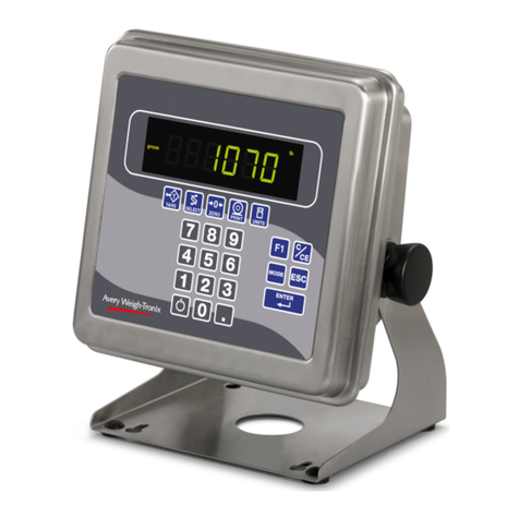
Avery Weigh-Tronix ZT350 User manual

Avery Weigh-Tronix
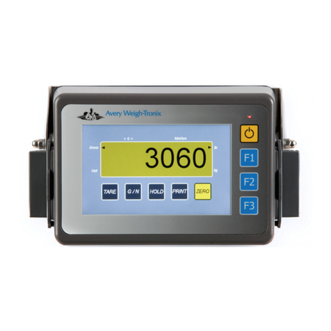
Avery Weigh-Tronix M3060 User manual

Avery Weigh-Tronix
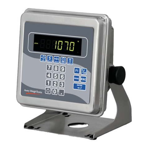
Avery Weigh-Tronix E1070 User manual

Avery Weigh-Tronix
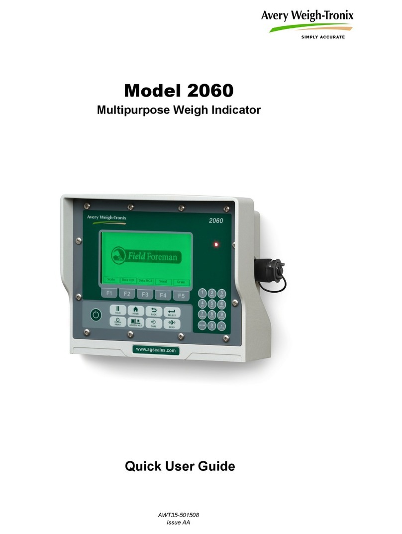
Avery Weigh-Tronix 2060 Instruction manual
Avery Weigh-Tronix
Avery Weigh-Tronix evolution Series User manual
Avery Weigh-Tronix
Avery Weigh-Tronix ZM205 User manual

Avery Weigh-Tronix
Avery Weigh-Tronix CUBETAPE PRO User manual

Avery Weigh-Tronix
Avery Weigh-Tronix ZM510 User manual
Avery Weigh-Tronix
Avery Weigh-Tronix WPI-135 User manual
Avery Weigh-Tronix
Avery Weigh-Tronix E1010 User manual