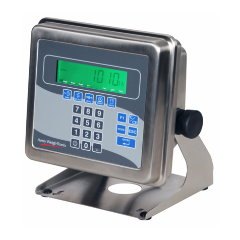
Avery Weigh-Tronix WPI-135 User manual

WPI-135 Indicator
Service Manual

2

3
Table of Contents
Table of Contents ......................................................................................................3
Specifications ............................................................................................................4
Introduction ...............................................................................................................5
About This Manual ..............................................................................................5
Front Panel Keys and Functions................................................................................5
Hard Keys ...........................................................................................................6
Soft Keys.............................................................................................................7
Menu Structure ..........................................................................................................7
Instructions for Accessing the Menus .................................................................8
User Menu .................................................................................................................8
User-CLOCK.......................................................................................................9
User-SELECT ...................................................................................................10
User-SET ..........................................................................................................11
User-VIEW........................................................................................................12
Configuration Menu .................................................................................................14
Configuration-MENU1 .......................................................................................16
Configuration-MENU2 .......................................................................................19
Configuration-MENU3 .......................................................................................23
Configuration-MENU4 .......................................................................................25
CalibratationMenu ..................................................................................................25
Calibrate-SETUP...............................................................................................26
Calibrate-CAL....................................................................................................27
Calibrate-INFO ..................................................................................................30
Calibrate-EXIT ..................................................................................................31
Test Menu ...............................................................................................................32
Disassembly and Reassembly ................................................................................34
Appendix 1: Display Samples ..................................................................................37
Appendix 2: Tips on Using Harmonizer ...................................................................39
Enclosure, Parts and Assy ......................................................................................41
Parts List .................................................................................................................42
System Block Diagram ............................................................................................43
Display/KeypadInterface Board ..............................................................................44
Power Supply and Serial I/O PC Board ...................................................................45
Main PC Board ........................................................................................................46
I/O Cable Identification Pinouts ...............................................................................47

4
Power Input
Excitation
Operational Keys
Operational Annunciators
Display
Display rate
A to D Conversion Rate
Unit of Measure
Capacity Selections
Incremental Selections
Decimal locations
Displayed Resolution
Audio Output
Time and Date
Internal Resolution
Harmonizer™digital filtering:
Standard input and outputs:
(internally)
Dimensions
Available Options
Operating Temperatures
Enclosure
Weight
Agencies
Warranty
85-265 VAC, 50/60Hz, single phase
10 Volts DC or 10 volts AC square wave capable of driving up to thirty-two 350-ohm weight
sensors. Indicator is also capable of driving three QuartzellTM transducers
Zero, Tare, Print, Units, Select, Enter, Escape, Clear, 0-9,
Decimal Point and Five Soft Keys labeled per selected operational routine.
Displayed symbols indicate motion, center of zero, unit of measure and more.
Model 135—1" H x 4.3" W vacuum fluorescent dot graphic display (32 X 128 dot layout)
Selectable, from once every ten seconds to 10 times per second
60 times per second
Pounds, kilograms, grams, ounces, pounds and ounces and four programmable custom units
Up to 10,000,000 selectable
Multiples and sub multiples of 1, 2, 5
88888888 pick any location relative to division size
Up to 1 part in 10,000,000
Audio tone for key contact assurance or operational alarms
Battery protected real time clock is standard
1,000,000 counts analog, QuartzellTM transducer higher
Fully programmable to ignore noise and vibration
Com 1: RS232, RS-485/422, QuartzellTM
Com 2: RS232, 20 mA current loop
Com 3: RS232, RS-485/422, QuartzellTM, 16550 UART
Com 4: RS232, RS-485/422, QuartzellTM, 16550 UART
(
One bidirectional signal per port
)
Four set point I/O ports via OPTO 22 I/O modules
1 Analog scale input
7.25" H x 11" W x 8.25" D (184 mm x 279 mm x 205 mm)
- Multiple analog scale inputs, up to seven additional
- Eight fully isolated, programmable analog outputs, selectable 4-20mA, 0-5VDC, 0-10VDC,
0-20mA, 0-24mA, ±5VDC, ±10VDC
- Remote expanded control interface for TTL or up to 64 solid state I/O modules
- OPTO 22 Generation 4 I/O Modules
- PC/104 Compatible expansion bus
- Expanded memory
- PC (AT) style alphanumeric keyboard
- Alphanumeric, serial PC-style keyboard RS232/TTL
- Field programmable with SimPoser®
- Fieldbus Network Interfaces
Device NetTM, ProfiBus®, ControlNetTM, InterBus-S, ModBus+, Ethernet (TCP/IP-ModBus)
14 to 104°F (-10 to 40°C), 10 to 90% relative humidity
Stainless steel wash down enclosure NEMA 4X
17 lb, 7.7 kg
NTEP Class III/IIIL:10,000d (pending)
Canada Consumer Affairs (pending)
UL/CUL (pending)
OIML (pending)
CE (pending)
FCC Class A
2 year
Specifications

5
Introduction
Front Panel Keys and Functions
About This Manual
Plug the WPI-135 into an easily
accessible grounded outlet
only. Never use the unit without
an appropriate earthground
connection.
Any computer based system
should have a separate,
grounded power circuit. We
recommend one for the
WPI-135.
This manual covers the information you need to configure and service your
WPI-135 Weight Processing Indicator.
Major sections of this manual are headed by titles in a black bar like
Intro-
duction
above. Subheadings appear in the left column. Instructions and text
appear on the right side of the page. Occasionally notes, tips, and special
instructions appear in the left column.
The front panel is shown in Figure 1.
Figure 1
WPI-135 Front Panel
The keys on the front panel of the WPI-135 are of two types, hard keys and
soft keys. Hard keys are labeled directly and soft key labels appear on the
display. Soft keys function differently at different times so their labels change
as needed. (F1-F5)

6
Below are brief descriptions for each of the hard key functions:
Repeatedly press the SELECT key to scroll through the
available weight reading displays. (Examples - gross,
net, tare, minimum, maximum, etc.)
Press the UNITS key to scroll through the available
units of measure
Press the PRINT key to send data to a connected
printer. By default this key performs a DOPRINT
command followed by a DOACCUM command.
Press the TARE key to enter a tare weight, then repeat-
edly press SELECT to scroll through the tare, gross and
net weight displays.
Press the ZERO key to establish a zero reference. A
center-of-zero icon will be displayed when the weight is
within ¼division of zero.
Press the ESCAPE key to back out of menus or cancel
a numeric entry without accepting the value.
Press the CLEAR to clear values from the display
prompts. Press and hold the CE key for five seconds to
power down the indicator.
Press the ENTER key to enter a keyed in value or
accept a displayed choice.
The numeric keypad is for entering numbers.
Hard Keys
ON/OFF
If the indicator is powered down
via the
CE
key or by a sleep
mode, press any key to power
the indicator back up.
By default the print format #0
sends:
Gross
Tare
Net
They are transmitted from port
one only.
MOTION
During motion an
M
will appear
below the center-of-zero icon.

7
Soft Keys
Menu Structure
Soft keys are so-called because their function is not fixed. Function can
change as the mode of operation changes or as the program for your
particular setup changes.
Their are five soft keys (labeled F1-F5) located directly below the display. If
the keys are needed during any operation, a label for each active key
appears in the display directly above. There are only five key labels available
at one time but this does not limit the potential usefulness of these keys.
Programs can be created to enable one key to access another menu of
operation with more key names and functions.
There are several menus you use to setup or service the WPI-135. You
access the menus described below through the front panel. Each menu is
briefly described here. For in depth information about a menu, go to that
menu's section in this manual.
User menu (default password is 111)
The first menu covered in this manual is the User menu. The
items in this menu are the most commonly changed values and
parameters that you will use in the course of operating the WPI-
135.
Configuration menu (default password is 2045)
The second menu covered is the Configuration menu. These
items deal with some of the basic functions of the WPI-135 and
do not need to be accessed very often.
Calibration menu (default password is 30456)
The third menu is the Calibration menu. This section will need
to be accessed only when the scale is being calibrated or if you
change scale capacity or division size.
Diagnostic menu (default password is 911)
This menu is used to access several tests which can help
isolate problems.

8
IMPORTANT NOTE
The WPI-135 can be sealed for
legal for trade use and the
software protected from
change by a hardware connec-
tion. If the system is sealed,
programs cannot be down-
loaded or altered. If the system
is not sealed, programs can be
downloaded from the SimPoser
software. Sealing the WPI-135
does not affect the USER
menu. This menu can be
accessed and changed no
matter what the system seal
state is.
To seal or unseal the WPI-135,
remove the nylon plug on the
rear of the enclosure and press
the button underneath.
You must key in the password
within 5 seconds of accessing
the password screen or the
WPI-135 returns to normal
operation.
Instructions for
Accessing the Menus
User Menu
A different password is needed to access each menu. Once you access the
menu you want, the display presents a series of soft key choices. By press-
ing the appropriate soft key and following text prompts on the display, you
can set up your WPI-135 to suit your needs.
Following are the instructions you need to access the menus of the WPI-
135.
1. Press and hold the ESCAPE key
until the WPI-135 beeps. . . The display asks for a password and
looks like Figure 2.
Figure 2
Password display
2. Key in the password for the
menu you want to access and
press ENTER. . . The soft keys for the menu appear.
After you are finished in a menu you can press the EXIT soft key to return to
normal operation. You may be asked if you want to save changes you have
made. Follow the instructions on the display.
Below are the details for each menu.
Access the User menu using the instructions found in
Instructions for
Accessing the Menus
. Use the default password 111. You will see the
screen shown in Figure 3.
Figure 3
User menu soft key group
Figure 4 is a flowchart showing what soft keys or choices appear as you
press the soft keys shown in Figure 3.

9
The values under SELECT in
the flowchart to the right are
not saved after a power down
and power up.
User
—CLOCK
Figure 4
Soft key flowchart for User menu
Press the CLOCK soft key to access the time and date setting function.
1. The display shows the current
hour value. If this is not correct
key in a new value and press
ENTER or press ENTER to
accept the current value. . . The display shows the minutes
value.
2. Repeat step 1 for minutes,
seconds, year, month and day.
(The day of the week is
calculated automatically from the
four digit year.) Display returns to display shown in
Figure 3.
Hours must be entered in
military format:
23 = 11pm
13 = 1pm
1 = 1am
The User menu is not affected
if the indicator is sealed or
unsealed.

10
The display mode you pick
may not be the one that
appears on the display. A
display mode called out in the
WT BASIC program overrides
the setting you make through
the front panel.
While in the this menu the
display will show USER-
SELECT in the top left to
remind you of where you are in
the USER menu.
User
—SELECT
—DISP
User
—SELECT
—SCALE
You cannot select a scale
number unless it has been
activated in the SimPoser
program and downloaded to
the WPI-135, or enabled in the
Config menu.
User
—SELECT
User
—SELECT
—TARE
Press the SELECT soft key to access the User—SELECT soft key group:
DISP Press this key to set the current display mode and active value
SCALE Press this key to select the scale number you want to use.
TARE Press this key to enter a known tare weight.
UNIT Press this key to select the active units of measure.
Following is a detailed description of the four functions listed above.
If you press the DISP soft key, follow these instructions:
1. The display shows the current
display mode number. Press
ENTER to accept this value or
key in a new number from the list
in Appendix 1, then press
ENTER to accept it. The display asks for the ACTIVE
VALUE. This is the active display
value.
2. Choose one of the following
active display values by keying
in 0-13, then press ENTER. . . The display returns to the USER-
SELECT screen.
0 = Gross 4 = Max 8 = Count Total 12=Piece Weight
1 = Net 5 = Rate of Change 9 = Trans. Total 13=ADC
2 = Tare 6 = Gross Total 10=Count
3 = Min 7 = Net Total 11=Variable
If you press the SCALE soft key the display will ask you to select a scale
number. The currently active scale number is displayed. You can simply
type a new scale number and press the ENTER key. If you have multiple
scales attached to the indicator, this function chooses which scale's weight
is displayed and which one the ZERO and TARE keys will affect.
If you press the TARE soft key the display will show the current tare value
for the active scale. You may key in a new tare weight and press the ENTER
key to override the previous tare weight.
Variable (#11) is a variable
value called out in a WT-
BASIC program. ADC (#13)
stands for Analog to Digital
Counts.

11
User
—SELECT
—UNIT
User
—SET
User
—SET
—GRAPH
User
—SET
—PEAKS
If you press the UNIT soft key the display will ask you to key in a number (0-
6) which represents the value you want to be active. Below are the seven
units to choose from and the corresponding number you need to key in for
this function:
0- lb 3- oz 6- custom 2
1- kg 4- lb oz 7 - custom 3
2- g 5- custom 1 8 - custom 4
Press the EXIT soft key to return to the USER menu soft key group.
Press the SET soft key to access the User—SET soft key group shown
below:
GRAPH Press this key to set the parameters for bar graph and check-
weighing functions.
PEAKS Press this key to reset the Min/Max.
ACCUM Press this key to set the accumulator totals.
PCWT Press this key to set the pieceweight for counting functions.
EXIT Press this key to go back to the previous soft key set.
Following is a detailed description of the four functions listed above.
If you press the GRAPH soft key, follow these instructions:
1. The current MIN setting is
displayed. Press ENTER to
accept this value or key in a new
value and press ENTER. . . The UNDER value is displayed.
2. Repeat step 1 and accept or
change the value, for UNDER,
OVER, MAX and BASIS values.
BASIS is same as the active
values (0-13) shown below. These values now apply when using
the bar graph or checkweighing
display.
0 = Gross 4 = Max 8 = Count Total 12=Piece Weight
1 = Net 5 = Rate of Change 9 = Trans. Total 13=ADC
2 = Tare 6 = Gross Total 10=Count
3 = Min 7 = Net Total 11=Variable
If you press the PEAKS soft key the display asks if you want to reset the
MIN and MAX values now in memory. You are given the choice of YES or
NO. After choosing the display returns to the USER-SET menu display.
Variable (#11) is a variable
value called out in a WT-
BASIC program. ADC (#13)
stands for Analog to Digital
Counts.

12
User
—SET
—ACCUM
User
—SET
—PCWT
User
—VIEW
User
—VIEW
—VERS
If you press the ACCUM soft key, follow these instructions:
1. The display shows you the
current GROSS TOTAL in the
accumulator. You can change
this by keying in a new number
and pressing ENTER or press
ENTER to move to the next
ACCUM value. . . The display shows the NET TOTAL
value.
2. Repeat step 1 for NET TOTAL,
COUNT TOTAL, and
TRANS(action) TOTAL. . . The display returns to the USER-
SET screen.
If you press the PCWT soft key the display shows the current value for the
piece weight. Accept this by pressing the ENTER key or key in a new piece
weight and press ENTER.
Press the EXIT key to return to the User menu soft key group.
Press the VIEW soft key to access the User-VIEW soft key group:
VERS Press this key to see WPI-135 firmware part number, revision
information (time, date and revision letter), serial number, Xilinx
part number and revision, and information about a downloaded
SimPoser program (license number, company name, version
number, name of file and time and date downloaded.
SEAL Press this key to view/set the condition of the physical seal
setting.
VARS Press this key to view the BASIC variables.
STORES Press this key to view the numeric and string values used with
store and recall.
COUNT Press this key to view the calibration and configuration audit
counters.
Following is a detailed description of the functions listed above.
If you press the VERS soft key you will see the following information:
•Firmware version
•Part number and revision level
•Serial number of the indicator
•XILINX version
•XILINX part number
•XILINX revision level

13
User
—VIEW
—SEAL
User
—VIEW
—VARS
User
—VIEW
—STORES
•SimPoser license number and license holder of the person that saved
the file
•SimPoser license number and license holder of the person that down-
loaded the file
•Version of the SimPoser that created the file
•File name
•Time and date file was created
Press any key again and the User-VIEW soft key set is displayed.
Press the SEAL soft key to see the current state the physical seal setting.
The display will show
Seal Status:
Sealed
or
Unsealed
. Press the seal
switch (S1) to toggle the physical seal state of the indicator.
If you press the VARS soft key you will be able to scroll through the vari-
ables you have in your basic program. Press the FIRST soft key to see the
first one and the NEXT soft key to scroll to the next one. Repeat this until
you are through and press the EXIT soft key to return to the User—VIEW
menu.
If no variables are defined the screen will show NO VARIABLES DEFINED.
If you press the STORES soft key, follow these instructions:
1. The display asks if you want to
DISPLAY NUMERICS?, and
gives you the choice of YES or
NO. If you press YES the display
will look like this:
2. Press PREV (previous) to see
the previous numeric record.
Press NEXT to see the next
numeric record. Press SELECT
and the display will let you enter
a specific numeric record number.
When you press ENTER that
record number will be displayed.
If you press the
Prev
key when
Store (0) is displayed, the
display will show the max
memory location. This is a
good way to see how much
memory is available for your
WT-BASIC program.

14
Configuration Menu
You must key in the password
within 5 seconds of accessing
the password screen or the
WPI-135 returns to normal
operation.
3. If you press NO in step 1 the
following screen is displayed.
4. This screen lets you view all the
strings stored in your BASIC
program. View them the same
way you did the numeric values.
5. Press EXIT to return to the
User-VIEW menu.
Press ESC to return to the User menu. Press EXIT to return to normal
operation. You have now seen all the parts of the User menu.
Access the Configuration menu using the instructions found in
Instructions
for Accessing the Menus
. Use the default password 2045. You will see the
screen shown in Figure 5.
Figure 5
Configuration menu display
Figure 6 is a flowchart showing what soft keys or choices appear as you
press the soft keys shown in Figure 5.
If you press the
Prev
key when
Store (0) is displayed, the
display will show the max
memory location. This is a
good way to see how much
memory is available for your
WT-BASIC program.

15
Figure 6
Soft key flowchart for Configure menu

16
Configuration
—MENU 1
Configuration
—MENU1
—#SCL
Configuration
—MENU1
—UNITS
Press the MENU1 soft key to access the following soft key group:
#SCL Press this key to set number of active scales,
UNITS Use this key to enable/disable units of measure.
KEYS Use this key to enable or disable front panel keys
SERIAL Use this key to set port #, baud rate, parity, databits, hand-
shake, mode, and EOM character.
VALS Use this key to enable/disable values to be shown in the main
weightdisplay
Following are detailed instructions for setting these parameters.
If you press the #SCL soft key, follow these instructions:
1. The display will show the number
of active scales. Accept this by
pressing the ENTER key or key
in the number of attached
scales and press the ENTER
key. . . The display returns to the MENU1
display.
If you press the UNITS soft key, follow these instructions:
1. The display asks if you want to
enable the LB unit of measure
and shows you the current state
(
ON
or
OFF
). If the condition is
as you want it, simply press the
ENTER key. If you want to
change the condition, press the
YES or NO soft key, then the
ENTER key to move to the next
unit of measure. . . The kilogram unit of measure is the
next one shown.
2. Repeat step 1 for kilograms,
grams, ounces, pounds &
ounces, and custom units 1 - 4.
The display asks for calibration
units, then the number of custom
units that are equivalent.
Key in the values and press
ENTER. . . The display returns to the MENU1
display.
Custom Units prompts for how
many calibration units equal
how many custom units.
Example: 2000 lb = 1 ton

17
CTS is a hardware handshake
(ready/busy) which requires
two extra wires in your cable.
Xon/Xoff is a software hand-
shake requiring no additional
hardware.
Configuration
—MENU1
—KEYS
Configuration
—MENU1
—SERIAL
If you press the KEYS soft key, follow these instructions:
1. The display asks if you want to
enable the SELECT key
and shows you the current state
(
ON
or
OFF
). If the condition is
as you want it, simply press the
ENTER key. If you want to
change the condition, press the
YES or NO soft key, then the
ENTER key to move to the next
key. . . The UNITS key is the next one
shown.
2. Repeat step 1 for UNITS,
PRINT, TARE, ZERO,
AUTOTARE and KEYPAD
TARE . . . The display returns to the MENU1
display.
If you press the SERIAL soft key, follow these instructions:
1. The display prompts you for
serial port # to configure. Press
ENTER if displayed port is OK or
key in a new port number and
press ENTER. . . The baud rate is displayed.
2. Press ENTER to accept the
baud rate or key in a new baud
rate from the table below and
press ENTER. . . The parity code number is displayed.
Baud Rates
300 9600
1200 19,200
2400 38,400
4800 56,700
3. Press ENTER to accept the
parity or key in a new parity code
number from the table below and
press ENTER. . . The databits setting is displayed.
Parity Codes
0 = NONE 3 = SET
1 = ODD 4 = CLEAR
2 = EVEN
4. Press ENTER to accept the
databits setting or key in the new
databits value (7 or 8) and press
ENTER. . . The handshake protocol code
number is displayed.

18
EOM ASCII code #13 is
carriage return.
Configuration
—MENU1
—VALS
5. Press ENTER to accept the
handshake protocol setting or
key in a new code number for
the handshake from the table
below and press ENTER. . . The mode code number is dis-
played.
Handshake Protocol Codes
0 = NONE 2 = Xon / Xoff
1 = CTS 3 = BOTH
6. Press ENTER to accept the
mode setting or key in a new
code number from the table
below and press ENTER. . . The EOM (end of message) value is
displayed.
Serial Mode Control Codes
0 = BASIC control 2 = Disabled 4 = Computer
1 = Keyboard 3 = Multidrop
BASIC Control - Control of the serial port is through the BASIC program
executing in the WPI-135.
Keyboard - Control of the serial port is through an attached key-
board.
Disabled - The serial port is not in use for this configuration.
Multidrop - The serial port is configured in RS-485 Multidrop mode.
Computer- Makes certain indicator functions available via serial
port.
7. Press ENTER to accept the
EOM character or key in a new
number from 0-256 and press
ENTER. . . The display returns to the
CONFIGURE-MENU1display
unless you are configuring port 2 or
4. If you are configuring port 2 or 4,
you must choose from the following:
Serial port 2: RS-232 or 20mA
Serial port 4: RS-232 or IR (Infrared)
Press the VALS soft key to enable or disable the value which can be dis-
played on the main weight display when using the SELECT key. Below are
the instructions for the VALS soft key:
1. The current setting (enabled ON
or OFF) for the GROSS display
value is displayed. Press YES to
enable the active value or NO to
disable this active display value,
then press ENTER . . The current setting for the NET
active value is displayed.

19
Configuration
—MENU 2
2. Repeat step 1 for all the display
values (NET, TARE, MIN., MAX.,
ROC, G-TOT, N-TOT, C-TOT,
#-TOT, COUNT, VALUE, PCWT
and ADC. . . The display returns to the
MENU3display.
This completes the instructions for all the parameters of Menu1.
These configuration items pertain to a particular scale. If you have enabled
multiple scales, you will be asked which scale you want to configure. Key in
the scale number, press ENTER and continue. If you have enabled only one
scale, continue with the following instructions.
Press the MENU2 soft key to access the following soft key group:
MOTION Use this key to set the motion detection window size in divisions
and the time window in seconds.
AZT Use this key to set the AZT window size in divisions and the
time window in seconds.
FILTER Use this key to set up the Harmonizer filtering to counteract
vibration of the scale.
ZERO Use this key to set the zero range. This is a percent of capacity
that is allowed to be zeroed when pressing the ZERO key. (0-
100% allowed)
MORE This accesses the following three soft keys.
RATE Press this key to configure the display update rate in updates
per second.
ROC ROC stands for Rate of Change. Press this key to set up your
WPI-135 Indicator to calculate Rate of Change for flow rate, or
weight/time,applications.
RZ/TO Press this key to configure Print Return to Zero (RZ), Accumula-
tor RZ, Accumulator Timeout, Print Timeout and Zero Timeout.
Following are detailed instructions for setting these parameters.
Use this key to set the motion detection window size in divisions and the
time window in seconds.
For example: If you set divisions to 3 and seconds to 1, if the weight value
does not change more than 3 divisions in one second, the scale or weight is
considered stable.
If you press the MOT'N soft key, follow these instructions:
1. The current value for the motion
window size, in divisions, is
shown. Press ENTER to accept
this value or key in a new value
and press ENTER. . . The current time window in seconds
is displayed.
Configuration
—MENU 2
—MOT'N

20
Configuration
—MENU 2
—AZT
Configuration
—MENU 2
—FILTER
2. Press ENTER to accept this time
period or key in a new value and
press ENTER. . . The display returns to the MENU2
display.
Use this key to set the AZT window division size and time window in sec-
onds. The division size you pick defines a range above and below zero.
When scale weight is inside this range for the number of seconds you
picked, ½of the weight will be zeroed. The indicator will repeat removing ½
the weight every X seconds. X being the number of seconds you have
picked.
If you press the AZT soft key, follow these instructions:
1. The current value for the AZT
window size, in divisions, is
shown. Press ENTER to accept
this value or key in a new value
and press ENTER. . . The current time window in seconds
for AZT is displayed.
2. Press ENTER to accept this time
period or key in a new value and
press ENTER. . . The display returns to the MENU2
display.
Use this key to set up the Harmonizer filtering to counteract vibration of the
scale. A full explanation is given below. See Appendix 2 for tips on using
Harmonizer.
The A-D weight conversion happens 60 times per second in the WPI-135.
AVG is the number of conversions you want to average. For example, if you
pick 30, the unit will average the weight values from the last 30 conversions
or ½second and uses that value for displayed data.
The next choice you have is for turning the Harmonizer filtering on or off. If
you turn the Harmonizer filtering on you need to set the Harmonizer Con-
stant. Typical values are between 1-10. Set the number low for small
vibration problems and higher for more dampening effect.
The purpose of the Harmonizer Threshold is so the indicator will respond
quickly to large weight changes. Harmonizer Threshold is the amount of
weight change, in calibration units, beyond which the Harmonizer will be
temporarily disabled. For example, if you set this to 10 lbs, a weight change
over 10 pounds occurring during the sample time (½sec. in our example)
will disable the Harmonizer until the weight change during the sample time
drops below 10 lbs.
If you press the FILTER soft key, follow these instructions:
1. The display shows the current
value for the number of samples
to average. Press ENTER to
accept this value or key in a new
value and press ENTER. . . The display shows the state of the
Harmonizer filtering( ON or OFF).
In the SimPoser software the
Harmonizer constant choices
are 1 through 10. This setting
is to be made in the "real
world" on a working system so
there are more menus avail-
able from the front panel.
Table of contents
Other Avery Weigh-Tronix Measuring Instrument manuals
Avery Weigh-Tronix
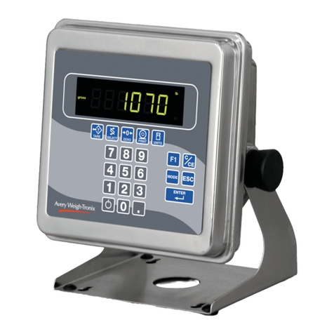
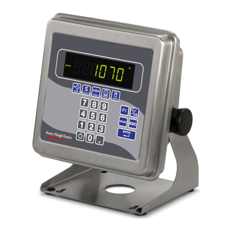
Avery Weigh-Tronix E1070 User manual
Avery Weigh-Tronix
Avery Weigh-Tronix ZM510 User manual

Avery Weigh-Tronix
Avery Weigh-Tronix evolution Series User manual

Avery Weigh-Tronix
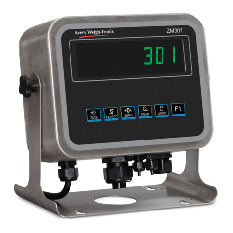
Avery Weigh-Tronix ZM301 User manual

Avery Weigh-Tronix
Avery Weigh-Tronix ZT350 User manual

Avery Weigh-Tronix
Avery Weigh-Tronix CUBETAPE PRO User manual

Avery Weigh-Tronix
Avery Weigh-Tronix ZM205 User manual

Avery Weigh-Tronix
Avery Weigh-Tronix 615XL User manual
Avery Weigh-Tronix
Avery Weigh-Tronix 2060 Instruction manual
Avery Weigh-Tronix
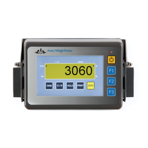
Avery Weigh-Tronix M3060 User manual