D
E
F
E
N
C
E
R
E
C
O
G
N
I
S
E
D
S
U
P
P
L
I
E
R
Department of Defence
Avlite Systems
AUSTRALIA
t: +61 (0)3 5977 6128
USA
t: +1 (603) 737 1310
w: www.avlite.com
e: info@avlite.com
V3_2013
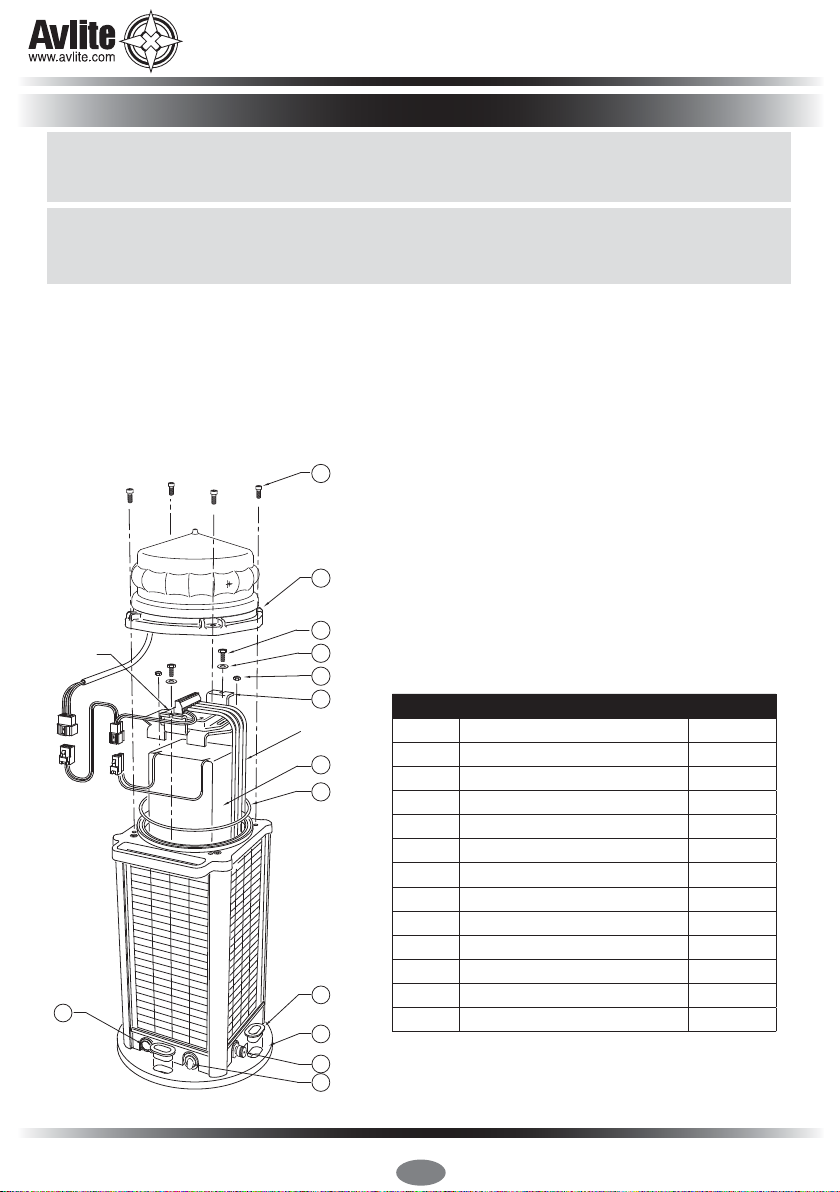
The AV-425-RF is a robust, completely self-contained LED light designed for
a range of emergency aviation applications including runway, threshold,
approach, helipad and tactical aireld lighting. Fitted with RF radio control,
this fully functioning light can be controlled from the tower with no costly
cabling or trenching required.
The unit is made from cast aluminium, subject to 7-stage powder-coating in aviation
yellow. Four premium grade solar modules are integrated into the assembly and mounted
to collect sunlight at all angles.
The solar array charges the 24Ah battery during daylight hours, and at dusk the light will
automatically begin operation.
16 independently controlled LED drivers within the light optic (patents pending) allow the
AV-425-RF xture to operate as an omnidirectional or bi-directional assembly designed to
meet the photometric requirements of FAA L861 runway edge and threshold when set to
temporary high mode.
The AV-425-RF has non-precision IFR and VFR capability with both visible and near infrared
lighting outputs.The aireld lights can be controlled anywhere in the aireld by handheld
radio controller or in the air trafc control tower with virtually unlimited range using an
encrypted repeating mesh network.
The AV-425-RF wireless RF light has an extended range through the use of the AvMesh®
communication network.The proprietary AvMesh® network enables each light to transmit
and receive commands, allowing the aireld to be expanded or altered at any time.
AvMesh® is self-realizing, meaning once deployed the aireld lights will undertake a
period of network mapping, whereby the system automatically determines an efcient
path to relay command messages through the aireld.
AvMesh® has redundancy. Once the system has mapped an efcient relay of command
messages, a secondary sub-network is mapped for added redundancy.
The AV-425-RF has three selectable modes;
always on, dusk-till-dawn and standby.
When set to dusk-till-dawn mode, integrated
sensors in the light are able to detect
when the ambient light threshold drops
sufciently and the light will begin operation
automatically.
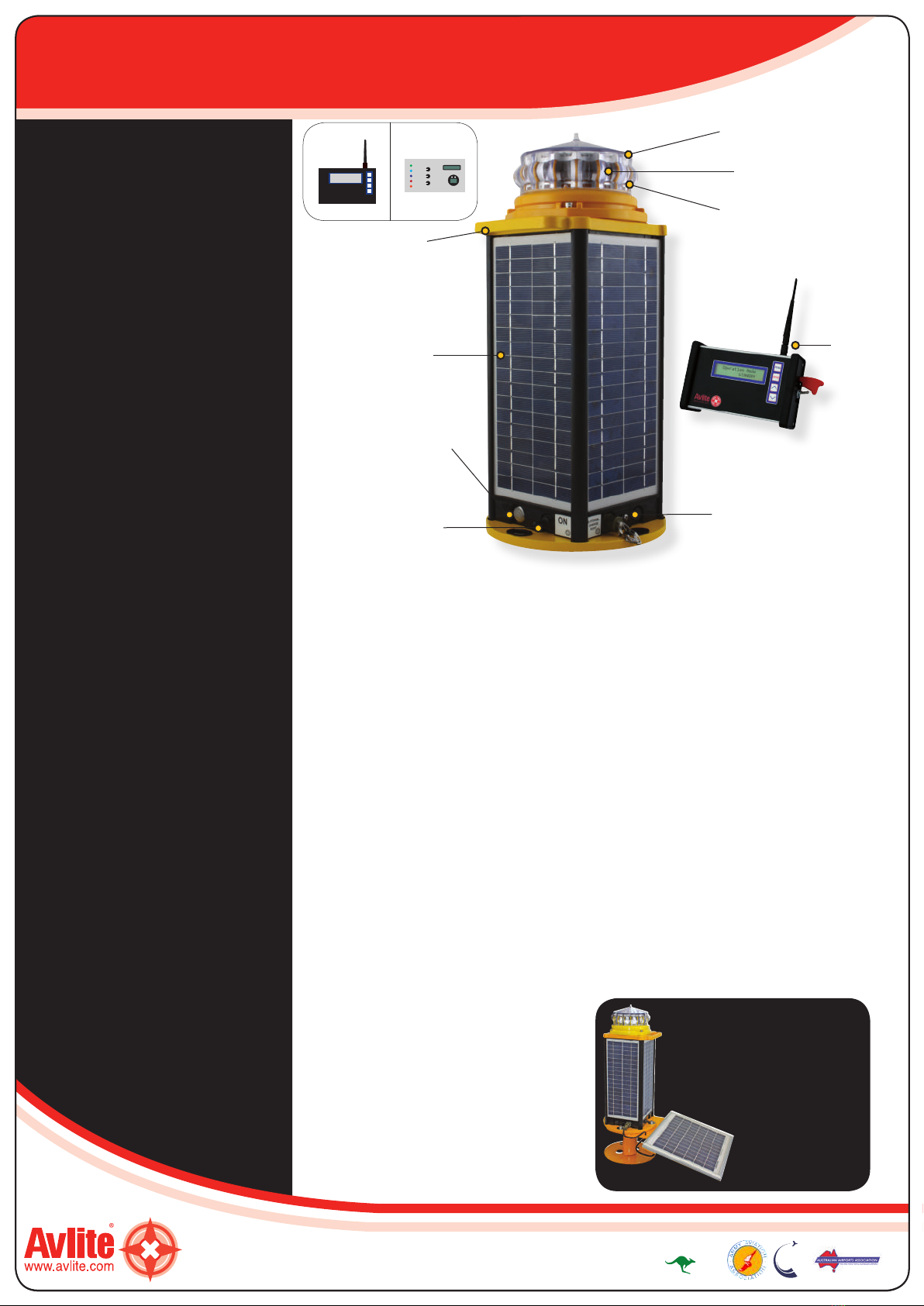
Radio Controlled Solar Aviation Light
AV-425-RF
Features
• Over 50hrs of continuous operation
at FAA non precision MIRLs per
AC/150-5345-46D L861 without
solar or auxiliary charge in
temporary high mode
OR
• Over 110hrs of continuous
operation at ICAO Annex 14
runway edge, 50cd
• Integrated and replaceable Solar
Panels - Enables continuous
operation
• Optional NVG Mode - Illumination
invisible to naked eye to support
covert operations
• Worldwide 2.4GHz Encrypted RF
Radio Control - Secure control of all
operational modes from anywhere
on the aireld. Worldwide ISM
use frequency
• AvMesh® integrated Mesh Network
- Each light is a receiver/transmitter
to expand communication range
• Radio Transceiver - Internal to light
head, no external antenna
• Modes of Operation -
Programmable lighting groups,
dusk-till-dawn operation,
adjustable intensity, sequence
ashing
Typical Applications
• Solar Runway Edge Light
• Solar Threshold Light
• Approach (Strobe & Fixed)
• Solar Obstruction Light
• Helipad
• Tactical
Compliance
•Designed to meet photometrics for
ICAO Annex 14 Volume 1,
‘Aerodrome Design and
Operations’. Runway Edge -
paragraph 5.3.9. Appropriate
for use as threshold - paragraph
5.3.10, 5.3.11 threshold light or
end light Approach - paragraph
5.3.4.1A & B, 5.3.4.8 simple
approach lighting system
• Designed to meet photometrics for
FAA AC/150-5345-46D L861
(High Intensity Mode)
The AV-SB-10 Solar Booster™
can be connected to AV-425-RF
light to provide additional solar
collection to charge the battery.
The Avlite Solar Booster™ can
be used in areas of reduced
sunlight to help ensure
optimum battery charge
or where longer
periods of high
intensity mode is
required.
12vdc input for
cable connection
(auxiliary charging
port system)
Integrated
handle
4 Integrated
user-replaceable
solar panels
Push button switch
to cycle through
operational modes
External ON/OFF
switch
16 segment,
multi-focus lens
Internal
2.4GHz RF module
LED light unit,
with visible and
near infrared
lighting outputs
Global
2.4GHz
RF Radio
control
Radio Control
Standard Optional
Light A
Light B
Light C
Light D
Light E
Pilot Activated
Lighting Control