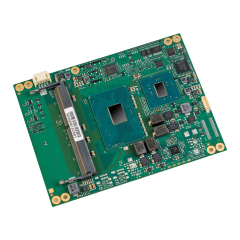
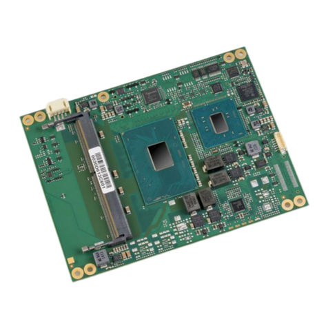
Avnet COM Express MSC C6C-AL User manual

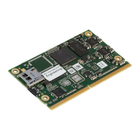
COM ExpressTM Compact Module
MSC C6C-AL
Type 6 Pinout
Intel®AtomTM / Celeron®/ Pentium®Series SOC
Rev. 1.0 2021-03-08
User Manual

MSC C6C-AL MSC C6C-AL User Manual 2 / 128
Preface
Copyright Notice
Copyright © 2017 MSC Technologies GmbH. All rights
reserved.
Copying of this document, and providing to others and the
use or communication of the contents thereof, is forbidden
without express authority of MSC Technologies GmbH.
Offenders are liable to the payment of damages.
All rights are reserved in the event of the grant of a patent or
the registration of a utility model or design.
Important Information
This documentation is intended for qualified audiences only.
The product described herein is not an end user product. It
was developed and manufactured for further processing by
trained personnel.
Disclaimer
Although this document has been generated with the utmost
care no warranty or liability for correctness or suitability for
any particular purpose is implied. The information in this
document is provided “as is” and is subject to change without
notice.
EMC Rules
This unit has to be installed in a shielded housing. If not
installed in a properly shielded enclosure, and used in
accordance with the instruction manual, this product may
cause radio interference in which case the user may be
required to take adequate measures at his or her owns
expense.
Trademarks
All used product names, logos or trademarks are property of
their respective owners.
Certification
MSC Technologies GmbH is certified according to DIN EN
ISO 9001:2015 standards.
Life-Cycle-Management
MSC products are developed and manufactured according
to high quality standards. Our life-cycle management
assures long term availability through permanent product
maintenance. Technically necessary changes and
improvements are introduced if applicable. A product-
change-notification and end-of-life management process
assures early information of our customers.

MSC C6C-AL MSC C6C-AL User Manual 3 / 128
Product Support
MSC engineers and technicians are committed to provide
support to our customers whenever needed.
Before contacting Avnet Integrated / MSC Technical
Support, please consult the respective pages on our web
site at www.msc-technologies.eu for the latest
documentation, drivers and software downloads.
If the information provided there does not solve your
problem, please contact our Avnet Integrated / MSC
Technical Support:
Phone: +49 - 8165 906 - 200
Email: support@msc-technologies.eu

MSC C6C-AL MSC C6C-AL User Manual 4 / 128
Contents
1USER INFORMATION .......................................................................................8
1.1 About this Manual............................................................................... 8
1.2 Symbols and Signal Words................................................................. 8
1.3 Table Cells with Gray Text.................................................................. 8
1.4 Intended Use ...................................................................................... 8
1.5 Non-intended use ............................................................................... 9
1.6 Electrostatic Sensitive Device............................................................. 9
1.7 Module Photos..................................................................................10
2TECHNICAL DESCRIPTION............................................................................12
2.1 Introduction.......................................................................................12
2.2 Key Features ....................................................................................13
2.3 Block Diagram ..................................................................................14
2.4 COM Express Implementation..........................................................15
2.5 Functional Units................................................................................17
2.6 Power Supply....................................................................................19
2.7 Power Dissipation............................................................................. 19
2.7.1 Running Mode.....................................................................................19
2.7.2 Power Dissipation (Standby Modes) ...................................................21
2.8 System Memory................................................................................22
2.9 Mechanical Dimensions.................................................................... 23
2.9.1 Compact module.................................................................................23
2.10 Thermal specifications......................................................................24
2.11 Use Conditions ................................................................................. 25
2.12 Signal description .............................................................................25
2.12.1 High Definition Audio...........................................................................26
2.12.2 Ethernet...............................................................................................26
2.12.3 Serial ATA...........................................................................................27
2.12.4 PCI Express Lanes..............................................................................27
2.12.5 Express Card Support.........................................................................28
2.12.6 USB.....................................................................................................28
2.12.7 LPC Bus..............................................................................................30
2.12.8 LVDS / eDP.........................................................................................31
2.12.9 Digital Display Interfaces.....................................................................33
2.12.10 Serial Interface Signals........................................................................36
2.12.11 Miscellaneous......................................................................................36
2.12.12 Power and System Management ........................................................37
2.12.13 General Purpose I/O ...........................................................................39
2.12.14 SDIO....................................................................................................39
2.12.15 SPI Interface........................................................................................40
2.12.16 Module Type Definition........................................................................41
2.12.17 Power and GND...................................................................................42
2.13 Pin List for MSC C6C-AL Module (Type 6).......................................42
3JUMPERS AND CONNECTORS......................................................................48
3.1 Jumpers.............................................................................................48
3.2 Fan Connector...................................................................................49
3.3 Camera Connector............................................................................49
4WATCHDOG.....................................................................................................50
5SYSTEM RESOURCES ...................................................................................51
5.1 PCI IRQ Routing................................................................................51
5.2 SMB Address Map ............................................................................52
6BIOS.................................................................................................................53
6.1 Introduction........................................................................................53
6.2 Startup Screen Overview ..................................................................53
6.3 Activity Detection Background...........................................................53
6.4 Aptio Setup Utility..............................................................................53
6.5 Configuring the System BIOS ...........................................................53
6.6 BIOS Menu Structure ........................................................................53
6.6.1 Menu Bar.............................................................................................55
6.6.2 Legend Bar..........................................................................................56
6.7 Main Menu.........................................................................................57
6.7.1 Board Info............................................................................................58
6.7.2 Hardware Monitoring............................................................................59
6.7.3 System Information..............................................................................60
6.7.4 Firmware Update .................................................................................60
6.7.5 Network Configuration .........................................................................62
6.8 Advanced Menu ................................................................................63
6.8.1 Trusted Computing (TPM) ...................................................................64
6.8.2 ACPI Settings ......................................................................................65
6.8.3 SMART Settings ..................................................................................65
6.8.4 Serial Port Console Redirection...........................................................65
6.8.5 Console Redirection Submenu............................................................66
6.8.6 CPU Configuration...............................................................................68
6.8.7 CPU Power Management Submenu....................................................69
6.8.8 AMI Graphic Output Protocol Policy ....................................................70
6.8.9 PCI Subsystem....................................................................................70
6.8.10 Network Stack Configuration ...............................................................71
MSC C6C-AL MSC C6C-AL User Manual 5 / 128
6.8.11 CSM Configuration..............................................................................71
6.8.12 NVMe Configuration............................................................................72
6.8.13 SDIO Configuration.............................................................................73
6.8.14 USB Configuration...............................................................................74
6.8.15 Security Configuration.........................................................................75
6.8.16 SIO WB627/ SMSC 3114 Configuration..............................................75
6.8.17 EC Hardware Monitoring.....................................................................77
6.8.18 EC Features Configuration..................................................................82
6.8.19 Module-specific Initialization................................................................83
6.8.20 Onboard GPIO configuration...............................................................84
6.8.21 System Component.............................................................................84
6.9 Chipset.............................................................................................. 85
6.9.1 Flat Panel Configuration......................................................................86
6.9.2 Backlight Control.................................................................................86
6.9.3 North Bridge........................................................................................87
6.9.4 South Bridge........................................................................................88
6.9.5 Uncore Configuration ..........................................................................88
6.9.6 South Cluster Configuration ................................................................89
6.9.7 HD Audio Configuration.......................................................................90
6.9.8 LPSS Configuration.............................................................................91
6.9.9 PCI Express Configuration..................................................................92
6.9.10 PCIE Express Root Port 0-3................................................................92
6.9.11 SATA Drives........................................................................................95
6.9.12 SCC Configuration ..............................................................................95
6.9.13 USB Configuration...............................................................................96
6.9.14 Miscellaneous Configuration ...............................................................96
6.10 Security............................................................................................. 98
6.10.1 Secure Boot.........................................................................................98
6.10.2 Key Management................................................................................99
6.11 Boot.................................................................................................102
6.12 Save & Exit......................................................................................104
6.13 Setup Controlled Update.................................................................107
6.14 Bios Update from EFI Shell.............................................................109
6.15 Bios Update from Linux...................................................................109
6.16 Bios Update from Windows.............................................................109
6.17 Blind Restoration of Bios default settings (no display available).....110
6.18 Bios Recovery .................................................................................110
6.19 Trusted Update................................................................................111
6.20 Jumpers...........................................................................................115
6.21 Post Codes......................................................................................115
7TECHNOTES..................................................................................................116
8EAPI................................................................................................................118
9TROUBLESHOOTING....................................................................................119

MSC C6C-AL MSC C6C-AL User Manual 6 / 128
Revision History
Rev.
Date
Description
1.0
2021-03-08
First Release

MSC C6C-AL MSC C6C-AL User Manual 7 / 128
Reference Documents
[1] COM Express Module Base Specification
COM Express Revision 2.1
Last update: April 10th, 2012
[2] PCI Local Bus Specification Rev. 2.1
PCI21.PDF
Last update: June 1st, 1995
http://www.pcisig.com
[3] ATA/ATAPI-6 Specification
d1410r3b.pdf
http://www.t13.org/
[4] Serial ATA Specification
Serial ATA 1.0 gold.pdf
Last update: August 29th, 2002 Rev.1.0
http://www.sata-io.org/
[5] IEEE Std. 802.3-2002
802.3-2002.pdf
http://www.ieee.org
[6] VESA Embedded DisplayPort Standard
eDP_v1_3 mem.pdf
Last update: 13.01.2012
http://www.vesa.org/
[7] Universal Bus Specification
usb_20.pdf
Last update: April 27th, 2000
http://www.usb.org
[8] Universal Serial Bus Revision 3.0 Specification
usb_30_spec_xxxxxx.zip
Last update: 13.08.2012
http://www.usb.org

MSC C6C-AL MSC C6C-AL User Manual 8 / 128
1 User Information
1.1 About this Manual
This user’s guide provides information about the components, features
and connectors available on the MSC C6C-AL COM ExpressTM
Compact Module.
1.2 Symbols and Signal Words
Safety Messages: Danger, Warning and Caution
No safety messages used in this manual, due to high compact module
security. The following paragraph shows the usual MSC standard.
Signal words call attention to a safety message and designate a degree
or level of hazard seriousness.
Signal word
Degree of hazard seriousness
Danger
Indicates a hazardous situation that, if not avoided,
will result in death or serious injury.
Warning
Indicates a hazardous situation that, if not avoided,
could result in death or serious injury.
Caution
Indicates a hazardous situation that, if not avoided,
could result in minor or moderate injury.
All safety messages have a safety alert symbol and are structured as
follows:
Danger, Warning or Caution
Type of hazard
Potential consequences of the hazard
Evasive or avoidance actions to be taken
Notice
Notices contain important information that should be observed. In case
of neglect the board can be damaged. All notices have the -symbol
and are structured as follows:
NOTICE: Notice text.
1.3 Table Cells with Gray Text
Cells with gray text contain information that is not supported on this
board.
.
1.4 Intended Use
High-performance embedded modules can perform various tasks in
infotainment systems, such as professional audio equipment for radio
and television, or sophisticated illumination engineering for theater
performances. The MSC C6C-AL module is based on Intel‘s multi-core
system-on-chip (SOC) Atom generation that integrates next generation
Intel processor core, graphics, memory, and I/O interfaces into one
solution. Do not use this Compact Module in any other circumstances,
as described herein.

MSC C6C-AL MSC C6C-AL User Manual 9 / 128
1.5 Non-intended use
NOTICE: Use the compact module in the specified temperature
ranges only!
NOTICE: Use the compact module in the specified humidity
ranges only!
1.6 Electrostatic Sensitive Device
The MSC COM Express Compact Module is an
electrostatic sensitive device. It is packed accordingly.
NOTICE: Handle the Compact Module at electrostatic-free
workstations only.
NOTICE: Do not handle or store the Compact Module near
strong electrostatic, electromagnetic, magnetic or radioactive
fields unless the Compact Module is contained within its original
packaging

MSC C6C-AL MSC C6C-AL User Manual 10 / 128
1.7 Module Photos
Top Side View
1
Top Side Memory Socket
2
MAC Address Label
3
Layout Revision
4
Board Identification Number (BID)
5
Board ID Label
6
BIOS Label
7
Camera Interface Connector
8
System On Chip (SOC)
9
Micro SD Card Connector
10
Fan Connector
2
1
3
4
5
6
7
8
9
10

MSC C6C-AL MSC C6C-AL User Manual 11 / 128
Bottom Side View
11
Bottom side memory socket
12
COM Express® connector
11
12

MSC C6C-AL MSC C6C-AL User Manual 12 / 128
2 Technical Description
2.1 Introduction
COM Express™ is an open specification from PICMG (PCI Industrial
Computer Manufacturer Group). It is a module concept to bring PCI
Express and other newer technologies like SATA, USB 3.0 and
different display interfaces onto a COM (Computer On Module).
A COM Express™ module is plugged onto an application-specific base
board and offers a migration path to future CPU technologies as they
become available. Utilizing different form factors, COM Express™ can
be used for deeply embedded solutions all the way up to high
performance platforms.
The design of the MSC C6C-AL module supports the Intel® AtomTM /
Celeron®/Pentium® System-on-Chip (SOC) platform enabling the
embedded application to provide high performance processing with an
excellent visual experience, together with power efficiency.
For evaluation and design-in of the COM Express™ modules MSC
offers evaluation baseboards and development motherboards
providing the interface infrastructure for the COM Express™ module
using PC type connectors for external access.
Currently four module sizes are defined in the COM Express
Specification 2.1: the Mini Module, the Compact Module, the Basic
Module and the Extended Module. The main difference between them
is the over-all physical size and the performance envelope supported.
All module sizes of the same type use the same connectors and pin-
outs and utilize several common mounting hole positions. This level of
compatibility permits a carrier board designed to accommodate an
Extended Module to also support a Basic or Compact Module.
Up to 440 pins are available between COM Express™ modules and
the Carrier Board.
To enhance interoperability between COM Express™ modules and
Carrier Boards, seven common signaling configurations (Pin-out Types)
have been defined to ease system integration.

MSC C6C-AL MSC C6C-AL User Manual 13 / 128
2.2 Key Features
The MSC C6C-AL COM Express module is designed as a type 6 module according to COM Express® Module Base Specification Revision 2.1.
Key features include:
Module size: 95 mm x 95 mm
Intel®AtomTM / Celeron®/ Pentium®Series System-on-Chip
(SOC)
Dual 220 pin connector (440 pins)
2x DDR3L SO-DIMM module up to 8 GB system capacity
Module topside socket should be filled first.
Eight USB 2.0 ports; 4 shared over-current lines
Four USB 3.0 ports
Two Serial ATA 6.0 Gbit/s ports
Micro SD card socket (max. speed UHS-I, bootable)
3 PCI Express lanes on A-B (5 PCIe lanes with optional PCIe
Gen 2 switch)
Support pins for two Express Cards
Display interfaces
othree independent display controllers
oDigital Display Interface (DDI) configurable as HDMI, DVI
or Display Port
oDual 24-bit LVDS channel (shared with eDP)
High definition digital audio interface (external CODEC)
Single GBit Ethernet interface (Intel® Ethernet Controller I210-
AT)
LPC interface
Two high speed UART ports (TX and RX only, Functionality
based on the 16550 and 16750 industry standards.)
Optional eMMCTM memory
Two MIPI®CSI 2.0 camera interfaces
(CSI-2 D-PHY 1.1 x4 and CSI-2 D-PHY 1.2 x2)
BIOS support for Super IO Winbond 83627 (on carrier board via
LPC interface)
Four GPI pins
Four GPO pins
+12V primary power supply input
+5V standby (optional) and 3.3V RTC power supply inputs
TPM module (TPM 2.0, SLB9670)
Automatic fan control
Watchdog timer

MSC C6C-AL MSC C6C-AL User Manual 14 / 128
2.3 Block Diagram

MSC C6C-AL MSC C6C-AL User Manual 15 / 128
2.4 COM Express Implementation
COM Express™ required and optional features for pin-out type 6 are summarized in the following table. The features identified as Minimum (Min.)
shall be implemented by all modules. Features identified up to Maximum (Max) may be additionally implemented by a module.
The column MSC C6C-AL shows the features implemented by the MSC module.
Type 6
MSC C6C-AL
Note
Min / Max
System I/O
A-B
PCI Express Lanes 0 - 5
1 / 6
5 / 3 (x1)
3 PCIe lanes without optional PCIe Gen 2 switch
A-B
LVDS Channels
0 / 2
2
1x dual channel, 2x24 Bit
A-B
eDP on LVDS CH A pins
0 / 1
1
A-B
VGA Port
0 / 1
0
A-B
TV-Out
NA
0
A-B
DDI 0
NA
0
A-B
Serial Ports 1- 2
0 / 2
2
HSUART. (Functionality based on the 16550 and 16750 industry standards. HSUART Slave Mode is
not supported. Serial Infrared (SIR) per the Infrared Data Association (IrDA) 1.0 is not supported.)
A-B
CAN interface on SER1
0 / 1
0
A-B
SATA Ports
1 / 4
2
SATA 6.0 GBit/s
A-B
HDA Digital Interface
0 / 1
1
A-B
USB 2.0 Ports
4 / 8
8
A-B
USB Client
0 / 1
0
A-B
USB 3.0 Ports
NA
0
A-B
LAN Port 0
1 / 1
1
Intel® Ethernet Controller I210-AT
A-B
Express Card Support
1 / 2
2
A-B
LPC Bus
1 / 1
1
A-B
SPI
1 / 2
2
C-D
PCI Express Lanes 16-31
0 / 16
0
C-D
PCI Express Graphics (PEG)
0 / 1
0
C-D
Muxed SDVO Channels
NA
0
C-D
PCI Express Lanes 6-15
0 / 2
0
C-D
PCI Bus - 32 Bit
NA
0
C-D
PATA Port
NA
0

MSC C6C-AL MSC C6C-AL User Manual 16 / 128
C-D
LAN Ports 1-2
NA
0
C-D
DDI 1-3
0 / 3
2
HDMI/DVI/DP
C-D
USB 3.0 Ports
0 / 4
4
System Management
A-B
SDIO (muxed on GPIO)
0 / 1
1
Max. UHS-I
A-B
General Purpose Inputs
4 / 4
4
A-B
General Purpose Outputs
4 / 4
4
A-B
SMBus
1 / 1
1
A-B
I2C
1 / 1
1
A-B
Watchdog Timer
0 / 1
1
A-B
Speaker Out
1 / 1
1
A-B
External BIOS ROM support
0 / 2
1
A-B
Reset Functions
1 / 1
1
Power Management
A-B
Thermal Protection
0 / 1
0
A-B
Battery Low Alarm
0 / 1
1
A-B
Suspend
0 / 1
1
A-B
Wake
0 / 2
2
A-B
Power Button Support
1 / 1
1
A-B
Power Good
1 / 1
1
A-B
VCC_5V_SBY Contacts
4 / 4
4
A-B
Sleep Input
0 / 1
1
A-B
Lid Input
0 / 1
1
A-B
Fan Control Signals
0 / 2
2
A-B
Trusted Platform Modules
0 / 1
1
TPM 2.0 module

MSC C6C-AL MSC C6C-AL User Manual 17 / 128
2.5 Functional Units
CPUs
(Type 3 BGA 1296
package)
Intel®AtomTM x5-E3930, 2C, 1.30GHz, 1.80GHz, 2MiB L2 Cache, 6.5W, 2ch DDR3L. (APL-I)
Intel®AtomTM x5- E3940, 4C, 1. 60GHz, 1.80GHz, 2MiB L2 Cache, 9.5W, 2ch DDR3L. (APL-I)
Intel®AtomTM x7-E3950, 4C, 1.60GHz, 2.00GHz, 2MiB L2 Cache, 12W, 2ch DDR3L. (APL-I)
Intel®CeleronTM N3350, 2C, 1.10GHz, 2.40GHz, 2MiB L2 Cache, 6W, 2ch DDR3L
Intel®PentiumTM N4200, 4C, 1.10GHz, 2.50GHz, 2MiB L2 Cache, 6W, 2ch DDR3L
Intel®PentiumTM J4205, 4C, 1.50GHz, 2.50GHz, 2MiB L2 Cache, 10W, 2ch DDR3L
AtomTM APL-I CPUs with TJUNCTION = -40°C to 110°C and integrated heat spreader
CeleronTM, PentiumTM with TJUNCTION = 0°C to 105°C
Memory
Two 204-pin DDR3L SO-DIMM sockets for up to 8GB non-ECC unbuffered DDR3L
Maximal height 1250mil = 31.75mm
PC3L-10600, PC3L-12800, PC3L-14900, DDR3L SDRAM (DDR3L-1333, DDR3L-1600, DDR3L-1866)
Intel®CeleronTM SKU: PC3L-10600, PC3L-12800, DDR3L SDRAM (DDR3L-1333, DDR3L-1600)
(Module topside socket should be filled first.)
SATA
2 SATA channels up to 6.0 GBit/s
USB
8 x USB 2.0, 4 x USB 3.0
COM Express™
Type 6 interface, fully compliant to COM Express Base Specification R2.1
PCI Express™
Three Gen2/Gen1 PCIe x1 channels. (Five channels PCIe x1 with optional PCIe switch)
LPC
Low Pin Count Bus for heritage interfaces
SPI
Serial Peripheral Interface for one 1.8 V SPI flash device
Graphics
Controller
Integrated Intel®HD Graphics Gen 9
LVDS
Dual channel 24-bit LVDS
Digital Display
Ports
1x eDP 1.3 (max. 4096x2160 @ 60 Hz)
2x Digital Display Interface (DDI)
DP 1.2 (max. 4096x2160 @ 60 Hz),
HDMI 1.4b (max. 3840x2160 @30 Hz)
Single-link DVI
Ethernet
10/100/1000Base-TX (Intel® Ethernet Controller I210-IT or I210-AT)

MSC C6C-AL MSC C6C-AL User Manual 18 / 128
Storage
Optional eMMCTM memory
Camera interface
2x MIPI®CSI 2.0 camera interface (Camera Serial Interface), CSI-2 D-PHY 1.1 x4 and CSI-2 D-PHY 1.2 x2
Serial Interface
Two High Speed UARTs. (Functionality based on the 16550 and 16750 industry standards.)
Watchdog Timer
Embedded controller creates watchdog alert and system reset
TPM
TPM module, TPM 2.0, SLB9670
Fan Supply
4-pin header for support of a 12V PWM fan
Real Time Clock
RTC integrated in Intel®SOC
CMOS Battery
External
System Monitoring
Voltages, temperatures, fan
Core voltage
3.3V onboard voltage
12V input voltage
5V SBY input voltage
CPU temperature (-40°C - 110°C, SKU-dependent)
System memory temperature
Board temperature
Fan speed and automatic fan speed control
Socket
Micro SD Card socket (max. UHS-I). This socket is designed for system internal use, so there is no ESD and EMI protection
implemented.

MSC C6C-AL MSC C6C-AL User Manual 19 / 128
2.6 Power Supply
+12V primary power supply input
+5V standby
Option, is not required for module operation.
If not present, customer must ensure that the supply voltages which
are generated on the carrier board are switched off during suspend
states, so that no current from the carrier board’s signal lines can
flow to the CPU board.
3.3V RTC power supply
Option, is not required for module operation.
BIOS SETUP data is stored in a nonvolatile backup memory device,
therefore configuration data will not get lost after power removal
(except for time and date information)
2.7 Power Dissipation
2.7.1 Running Mode
All measurements were made by plugging the MSC C6C-AL module
onto a MSC MB-EVA6 carrier. The module was equipped with two
4GByte memory modules M3ST-4GMSCDPC-P, 4GB DDR3L 1600
W/T SODIMM. The table below shows typical values which refer to
consumption of the module itself without consumption of the base
board and CPU fan.
The following applications have been tested with minimum 15
minutes measurement time:
Windows desktop (idle) under Microsoft Windows 10 64-bit.
Running Intel®Thermal Analysis Tool (TAT!) Ver. 6.x to achieve
TDP workload under Microsoft Windows 10 64-bit.
BurnInTest V7.1 Pro with test settings 100% CPU, 100% RAM,
100% 2D Graphics and 100% 3D Graphics.
Voltage
Input range
Power Consumption
+12V
+4.75V - 20 V
Refer to chapter 2.7
+5V Standby
+4.75V - 5.25 V
+3V RTC power
supply
+2.5V - 3.47V
Typ. 4.3 µA

MSC C6C-AL MSC C6C-AL User Manual 20 / 128
Module / CPU
Win 10 Idle
Win 10 TAT!
BurnInTest
average
peak
C6C-AL-E3930-N4261I (Intel®AtomTM x5-E3930, 2C, 1.30GHz,
1.80GHz, 2MiB L2 Cache, 6.5W, 2ch DDR3L)
3.2 W
10.4 W
12.2 W
6.4 W
C6C-AL-E3940-N5261I (Intel®AtomTM x5- E3940, 4C, 1.60GHz,
1.80GHz, 2MiB L2 Cache, 9.5W, 2ch DDR3L)
3.0 W
14.9 W
15.3 W
7.6 W
C6C-AL-E3950-N5261I (Intel®AtomTM x7-E3950, 4C, 1.60GHz,
2.00GHz, 2MiB L2 Cache, 12W, 2ch DDR3L)
3.1 W
20.6 W
24.4 W
8.7 W
C6C-AL-N3350-N4261C (Intel®CeleronTM N3350, 2C, 1.10GHz,
2.40GHz, 2MiB L2 Cache, 6W, 2ch DDR3L)
3.0 W
9.0 W1)
20.5 W1)
7.2 W
C6C-AL-N4200-N5261C (Intel®PentiumTM N4200, 4C, 1.10GHz,
2.50GHz, 2MiB L2 Cache, 6W, 2ch DDR3L)
3.2 W
11.0 W1)
26.3 W1)
10.9 W
1) TAT workload setting: CPU-All 100%, Gfx 80% in Intel®Thermal Analysis Tool Ver. 6.0.1030, because TAT do not offer TDP for this SKU.
Table of contents
Other Avnet Control Unit manuals

Avnet
Avnet PicoZed 7010 Installation manual

Avnet
Avnet AES-ACC-U96-ONCAM-MEZ User manual

Avnet
Avnet Azure Sphere Guardian-100 User manual

Avnet
Avnet UltraZed-EG Installation manual

Avnet
Avnet SMARC MSC SM2S-IMX8MINI User manual

Avnet
Avnet MSC Technologies COM Express C6C-BW User manual

Avnet
Avnet FMC-MULTI-CAM4 User manual

Avnet
Avnet Qorvo Installation manual

Avnet
Avnet Qseven MSC Q7-BT User manual

Avnet
Avnet ROHM Semiconductor User manual