Axiom SW212Al User manual

SW212A
Acve Subwoofer
USER MANUAL
revision 2021-11-03

2

3
Watch for these symbols:
The lightning ash with arrowhead symbol within an equilateral triangle is intended to alert the user to the presence of uninsulated
“dangerous voltage” within the product’s enclosure, that may be of sucient magnitude to constute a risk of electric shock to
persons.
The exclamaon point within an equilateral triangle is intended to alert the user to the presence of important operang and
maintenance (servicing) instrucons in the literature accompanying the appliance.
IMPORTANT SAFETY INSTRUCTIONS
1. Read these instrucons.
2. Keep these instrucons.
3. Heed all warnings.
4. Follow all instrucons.
5. Do not use this apparatus near water.
6. Clean only with dry cloth.
7. Do not block any venlaon openings. Install in accordance with the manufacturer’s instrucons.
8. Do not install near any heat sources such as radiators, heat registers, stoves, or other apparatus (including ampliers) that
produce heat.
9. Do not defeat the safety purpose of the polarized or grounding-type plug. A polarized plug has two blades with one wider than
the other. A grounding-type plug has two blades and a third grounding prong. The wide blade or the third prong are provided
for your safety. If the provided plug does not t into your outlet, consult an electrician for replacement of the obsolete outlet.
10. Protect the power cord from being walked on or pinched, parcularly at plugs, convenience receptacles, and the point where
they exit from the apparatus.
11. Only use aachments/accessories specied by the manufacturer.
12. Use only with the cart, stand, tripod, bracket, or table specied by the manufacturer, or sold with the apparatus. When a cart
is used, use cauon when moving the cart/apparatus combinaon to avoid injury from p-over.
13. Unplug this apparatus during lightning storms or when unused for long periods of me.
14. Refer all servicing to qualied service personnel. Servicing is required when the apparatus has been damaged in any way, such
as power supply cord or plug is damaged, liquid has been spilled or objects have fallen into the apparatus, the apparatus has
been exposed to rain or moisture, does not operate normally, or has been dropped.
15. Warning: to reduce the risk of re or electric shock, do not expose this apparatus to rain or moisture.
16. Do not expose this equipment to dripping or splashing and ensure that no objects lled with liquids, such as vases, are placed
on the equipment.
17. To completely disconnect this apparatus from the ac mains, disconnect the power supply cord plug from the ac receptacle.
18. The mains plug of the power supply cord shall remain readily operable.
19. This apparatus contains potenally lethal voltages. To prevent electric shock or hazard, do not remove the chassis, input
module or ac input covers. No user serviceable parts inside. Refer servicing to qualied service personnel.
20. The loudspeakers covered by this manual are not intended for high moisture outdoor environments. Moisture can damage
the speaker cone and surround and cause corrosion of electrical contacts and metal parts. Avoid exposing the speakers to
direct moisture.
21. Keep loudspeakers out of extended or intense direct sunlight. The driver suspension will prematurely dry out and nished
surfaces may be degraded by long-term exposure to intense ultra-violet (UV) light.
22. The loudspeakers can generate considerable energy. When placed on a slippery surface such as polished wood or linoleum,
the speaker may move due to its acouscal energy output.
23. Precauons should be taken to assure that the speaker does not fall o a stage or table on which it is placed.
24. The loudspeakers are easily capable of generang sound pressure levels (SPL) sucient to cause permanent hearing damage
to performers, producon crew and audience members. Cauon should be taken to avoid prolonged exposure to SPL in excess
of 90 dB.
This marking shown on the product or its literature, indicates that it should not be disposed with other household wastes at the end
of its working life. To prevent possible harm to the environment or human health from uncontrolled waste disposal, please separate
this from other types of wastes and recycle it responsibly to promote the sustainable reuse of material resources. Household users
should contact either the retailer where they purchased this product, or their local government oce, for details of where and
how they can take this item for environmentally safe recycling. Business users should contact their supplier and check the terms
and condions of the purchase contract. This product should not be mixed with other commercial wastes for disposal.
CAUTION
To prevent electric shock hazard,
do not connect to main power
supply while grille is removed.

4
LIMITED WARRANTY
Proel warrants all materials, workmanship and proper operaon of this product for a period of two years from the original date of purchase. If any
defects are found in the materials or workmanship or if the product fails to funcon properly during the applicable warranty period, the owner
should inform about these defects the dealer or the distributor, providing receipt or invoice of date of purchase and defect detailed descripon.
This warranty does not extend to damage resulng from improper installaon, misuse, neglect or abuse. Proel S.p.A. will verify damage on returned
units, and when the unit has been properly used and warranty is sll valid, then the unit will be replaced or repaired. Proel S.p.A. is not responsible
for any “direct damage” or “indirect damage” caused by product defecveness.
• This unit package has been submied to ISTA 1A integrity tests. We suggest you control the unit condions immediately aer unpacking it.
• If any damage is found, immediately advise the dealer. Keep all unit packaging parts to allow inspecon.
• Proel is not responsible for any damage that occurs during shipment.
• Products are sold “delivered ex warehouse” and shipment is at charge and risk of the buyer.
• Possible damages to unit should be immediately noed to forwarder. Each complaint for package tampered with should be done within eight
days from product receipt.
CONDITIONS OF USE
Proel do not accept any liability for damage caused to third pares due to improper installaon, use of non-original spare parts, lack of
maintenance, tampering or improper use of this product, including disregard of acceptable and applicable safety standards. Proel strongly
recommends that this loudspeaker cabinet be suspended taking into consideraon all current Naonal, Federal, State and Local regulaons. The
product must be installed be qualied personal. Please contact the manufacturer for further informaon.
FEDERAL COMMUNICATIONS COMMISSION (FCC) STATEMENT
This equipment has been tested and found to comply with the limits for a Class A digital device, pursuant to part 15 of the FCC Rules. These limits
are designed to provide reasonable protecon against harmful interference when the equipment is operated in a commercial environment. This
equipment generates, uses, and can radiate radio frequency energy and, if not installed and used in accordance with the instrucon manual, may
cause harmful interference to radio communicaons.
Operaon of this equipment in a residenal area is likely to cause harmful interference in which case the user will be required
to correct the interference at their own expense.
This device complies with Part 15 of the FCC rules. Operaon is subject to the following two condions:
(1) this device may not cause harmful interference, and
(2) this device must accept any interference received, including interference that may cause undesired operaon.
DECLARATION OF CONFORMITY
The product is in compliance with:
EMC Direcve 2014/30/EU, LVD Direcve 2014/35/EU, RoHS Direcve 2011/65/EU and 2015/863/EU, WEEE
Direcve 2012/19/EU.
EN 55032 (CISPR 32) STATEMENT
Warning: This equipment is compliant with Class A of CISPR 32. In a residenal environment this equipment may cause radio interference.
Under the EM disturbance, the rao of signal-noise will be changed above 10 dB.

5
INTRODUCTION
The SW212A is a very compact Bass-Reex subwoofer providing high output and extended low frequency response.
It is equipped with two 12” neodymium transducer with a 3.5” aluminium voice coil, large displacement suspension system and
composite reinforced, water repellent cone, able to provide clean and undistorted LF reproducon at very high SPL .
The system processing is based on the CORE2 DSP plaorm designed by the PROEL R&D Laboratories using one of the most advanced
SHARC DSP for audio applicaons. It features 40bit oang point resoluon and top-quality 24bit AD/DA converters, for a perfect
signal integrity, dynamic range in excess of 110dB, and superior sonic performance. The PRONET AX control soware, working on a
solid and reliable CANBUS based network protocol, provides an intuive interface for the remote control of the whole system, with
the possibility of EQing, delaying, managing the protecon funcons, and monitoring the status of the amplier.
The SW212A is powered by a CLASS D power amplier with digitally-controlled SMPS equipped with PFC, reducing power
consumpon (less than 0.9W in standby) while enhancing reliability and consistency in all operang condions. The high eciency
of the output stage improves overall performance delivering prisne power and clean output signal.
The SW212A has been mainly designed to provide the opmal low frequency extension to the AX16CL/AX8CL line array modules. The
built-in power module can provide 1400W to drive the two 12” woofers and 1400W to power up to four AX16CL line array modules
connected to the output SPEAKON. The built-in CORE2 DSP provides 4 presets for dierent combinaons: 2, 4 or 1 columns plus 1
user preset (addional presets for processing other AXIOM speakers are also available).
The SW212A features on the top panel a special metal plate and it comes with a dedicated bracket for fast coupling with the AX16CL’s
rigging hardware. Using this simple system, up to two AX16CL modules can be easily installed on an SW212A.
TECHNICAL SPECIFICATION
SYSTEM Amplier Type Class D with SMPS and PFC
System’s Acousc Principle Band-pass / Bass-reex Output Power 1400W + 1400W (Out1: SW212A - Out2:
AX16CL or other AXIOM loudspeakers)
Frequency Response (-6dB) 38 Hz - 220 Hz (Processed)
Maximum Peak SPL @ 1m 133 dB Mains Voltage Range 100 - 240 V AC @ 50/60Hz
TRANSDUCERS Consumpon* 700 W (nominal) / 2500 W (max)
Type Two 12” (320mm) woofer,
neodymium magnet, 3.5” (88mm) VC
IN / OUT Connectors Neutrik XLR-M / XLR-F
IN / OUT Net Connectors ETHERCON® (NE8FAV)
Cone High sness, water repellent Mains Connectors PowerCon® TRUE 1 (NAC3PXTOP)
ELECTRICAL Cooling Variable speed DC fan
Input Impedance 20 kΩ balanced, 10 kΩ unbalanced ENCLOSURE & CONSTRUCTION
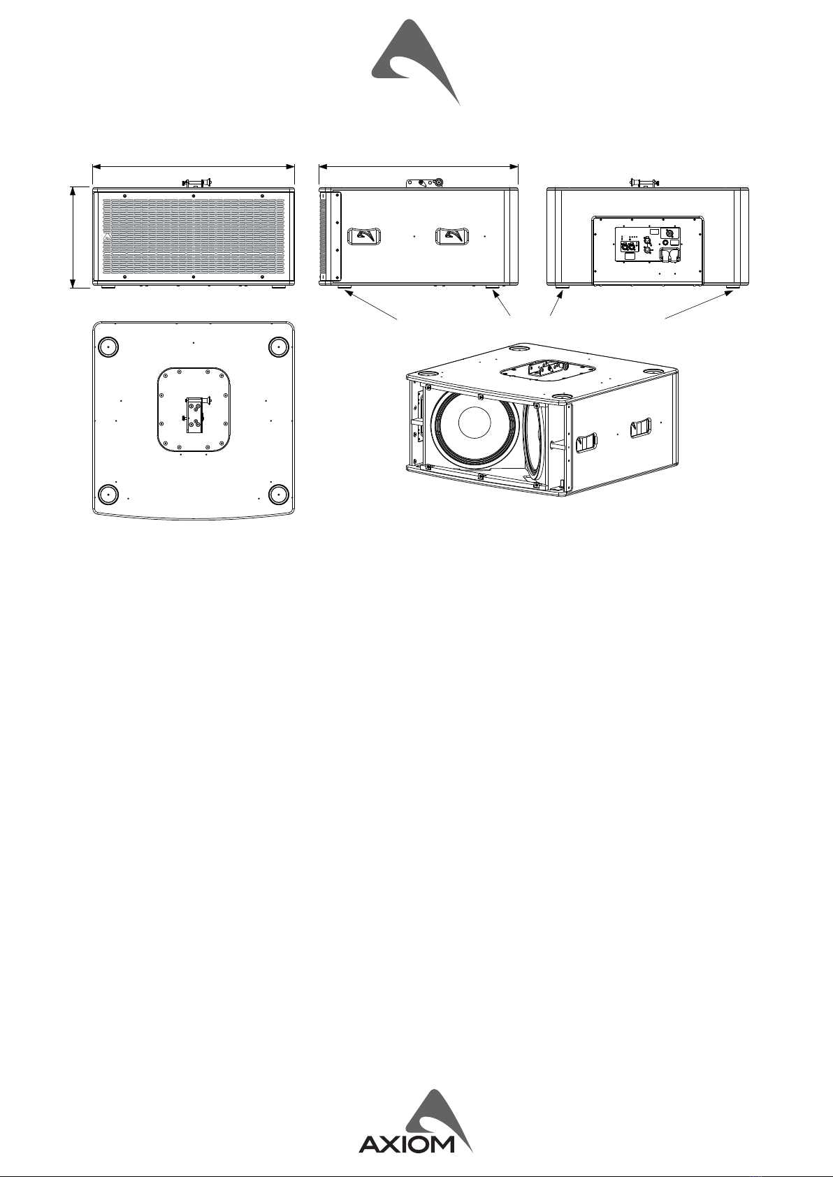
Input Sensivity +4dBu / 1.25 V Dimensions (W x H x D) 710 mm (27.9”) x 354 mm (13.9”) x 700 mm
(27.6”)
Signal Processing
CORE2 processing, 40bit oang
point SHARC DSP, 24 bit AD/DA
converters
Enclosure Material 18mm, reinforced phenolic birch
Paint High resistance, water based paint
Direct access Controls
4 Presets (2 x AX16CL / 4 x AX16Cl /
1 x AX16CL), Network Terminaon,
GND Link
Transport 4 handles
Net Weight 43.5 Kg (95.9 lbs)
Remote Controls PRONET AX control soware
Network protocol CANBUS
* Nominal consumpon is measured with pink noise with a crest factor of 12 dB, this can be considered a standard music program.
INDEX
INTRODUCTION ...........................5
TECHNICAL SPECIFICATION ..................5
MECHANICAL DRAWING ....................6
OPTIONAL ACCESSORIES ....................6
SPARE PARTS ..............................6
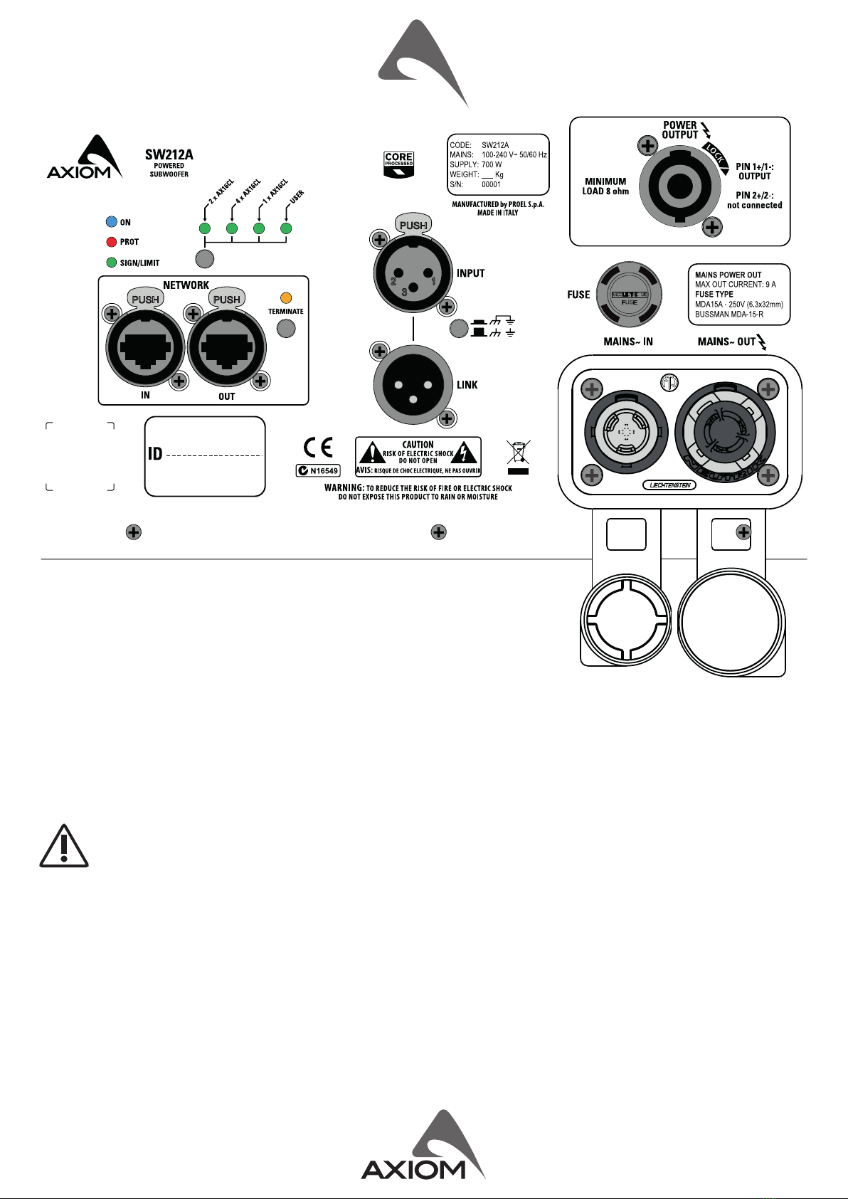
I/O AND CONTROL OPERATIONS ..............7
MAINS IN .................................7
MAINS OUT ...............................7
ON ......................................7
PROT ....................................7
SIGN LIMIT ...............................7
INPUT ...................................7
LINK .....................................8
GND LIFT .................................8
PRESET BUTTON ...........................8
NETWORK IN/OUT .........................8
TERMINATE ...............................8
POWER OUT ..............................8
PRONET AX OPERATION .....................9
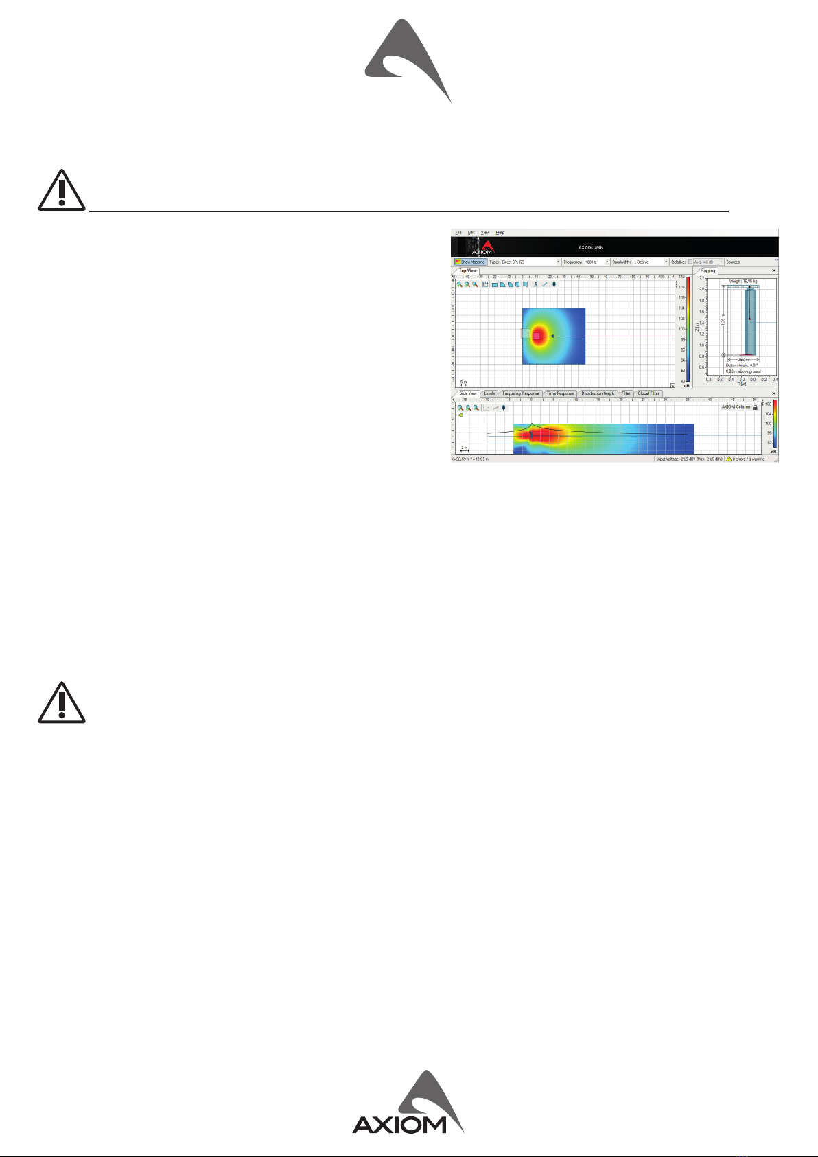
PREDICTION SOFTWARE: EASE FOCUS 3 .......10
BASIC INSTALLATION INSTRUCTIONS ..........10
PIN LOCKING AND SPLAY ANGLES SET UP ......11
STACKED INSTALLATION USING
SW212A SUBWOOFER AS BASE ..............12
SW212A + AX16CL CONNECTION EXAMPLES ...13

6
MECHANICAL DRAWING
OPTIONAL ACCESSORIES
NAC3FXWTOP Neutrik Powercon® TRUE1 (for power in)* NE8MXB Neutrik Ethercon PLUG* (carrier only for pre-made cables)
NAC3MXWTOP Neutrik Powercon® TRUE1 (for power out)* NE8MX6BT Neutrik Ethercon PLUG* (crimping CAT6a connector)
NC3MXXBAG Neutrik XLR-M* USB2CAND Dual Port PRONET network converter
NC3FXXBAG Neutrik XLR-F*
AXCASE13PT Flight-case for SW212A
see hp://www.axiomproaudio.com/ for detailed descripon and other available accessories.
*Note: See assembly instrucon downloadable from NEUTRIK WEB site at: hp://www.neutrik.com/
SPARE PARTS
NL4MP Neutrik Speakon® panel socket NAC3PXTOP Neutrik Powercon® TRUE1 Appliance inlet-outlet
94SPI10555O Locking Pin for AX16CL (with eyelet) SCNACPX Neutrik Rubber Sealing for NAC3PXTOP
95AXSTAX16CL AX16CL Bracket 91AMDSW212A Amplier module assembly
98SW212WZ4 12’’ woofer - 3.5” VC - 4 ohm 91FSV15A MDA15R 6.3x32mm 15 A T Fuse
71.0 cm
27.9"
70.0 cm
27.6"
35.4 cm
13.9"
Adjustable feet (turn to adjust the height)

7
I/O AND CONTROL OPERATIONS
MAINS IN
Powercon® NAC3FXWTOP power inlet connector. To switch the amplier on, insert the Powercon® connector and turn it clockwise into the
ON posion. To switch the amplier o, pull back the switch on the connector and turn it counter-clockwise into the POWER OFF posion.
MAINS OUT
Powercon® NAC3MXWTOP power outlet connector. This is connected in parallel with the MAINS IN. It is suited to link the supply of
another SW212A loudspeaker or other system for a maximum absorpon of 9A.
WARNINGS:
• Connect no more than one SW212A subwoofer unit to the MAINS OUT connector.
• Turn on each subwoofer unit one a me starng from the latest unit.
• In the case of product failure or fuse replacement, disconnect the unit completely from the mains power.
• Use a suitable power cable and mains plug to build the power cable, it must only be connected to a socket
corresponding to the specicaons indicated on the amplier unit. See assembly instrucon downloadable from
NEUTRIK WEB site at: hp://www.neutrik.com/
ON
This LED indicates power on status.
PROT
This red LED lights when the amplier module is in protect mode for an internal fault and, consequently, the amplier is muted.
SIGN LIMIT
This LED lights in green to indicate the presence of the signal and lights in red when an internal limiter reduces the input level.
INPUT
Audio signal input with locking XLR connector. It has a fully electronically balanced circuitry including AD conversion for the best
S/N rao and input headroom.

8
LINK
A direct connecon from the input connector to link other speakers with same audio signal.
GND LIFT
This switch li the ground of the balanced audio inputs from the earth-ground of the amplier module.
PRESET BUTTON
This buon has two funcon:
1) Pressing it while powering on the unit:
ID ASSIGN The internal DSP assigns a new ID to the unit for the PRONET AX remote control operaon. Each loudspeaker
must have a unique ID to be visible in the PRONET AX network. When you assign a new ID, all the other
loudspeakers with the ID already assigned must be ON and connected to the network.
2) Pressing it with the unit ON you can select the DSP PRESET. The selected PRESET is indicated by the corresponding LED:
2 x AX16CL This PRESET allows to connect two AX16CL column array elements to POWER OUTPUT speakon connector, see
example.
4 x AX16CL This PRESET allows to connect four AX16CL column array elements to POWER OUTPUT speakon connector,
see example.
1 x AX16CL This PRESET allows to connect one AX16CL column array elements to POWER OUTPUT speakon connector, see
example.
USER This PRESET corresponds to USER MEMORY no. 1 of the DSP and, as a factory seng, it’s the same to 2 x
AX16CL. If you want to modify it, you have to connect the unit to a PC, edit the parameters with PRONET AX
soware and save the PRESET into USER MEMORY no. 1.
NETWORK IN/OUT
These are a standard RJ45 CAT5 connectors (with oponal NEUTRIK NE8MC-B RJ45 cable connector carrier), used for PRONET AX
network transmission of remote control data over long distance or mulple unit applicaons.
TERMINATE
In a PRONET AX network the last device must be terminated (with an inner load resistance) especially in a long run cabling: press
this switch if you want to terminate the unit.
WARNING: only the last devices connected to the PRONET AX network must be always terminated, therefore all units
connected between two devices within the network must not be terminated never.
POWER OUT
SW212A is able to power the passive AX16CL column array module (or other loudspeakers) through the available power output on
the back panel.
WARNING: for the opmal protecon and equalizaon connect the exact number of AX16CL modules specied by the
selected PRESET.

9
PRONET AX OPERATION
PRONET AX soware has been developed in collaboraon with sound engineers and sound designers, in order to oer an “easy-to-
use” tool to setup and manage your audio system. With PRONET AX you can visualize signal levels, monitor internal status and edit
all the parameters of each connected device.
Download the PRONET AX app registering on MY AXIOM at the website at hps://www.axiomproaudio.com/.
For the network connecon the USB2CAN-D (with 2-port) converter oponal accessory is needed.
PRONET AX network is based on a “bus-topology” connecon, where the rst device is connected to the network input connector
of the second device, the second device network output is connected to the network input connector of the third device, and so
on. To ensure a reliable communicaon the rst and the last device of the “bus-topology” connecon must be terminated. This can
be done by pressing the “TERMINATE” switch near the network connectors in the rear panel of the rst and the last device. For
the network connecons simple RJ45 cat.5 or cat.6 ethernet cables can be used (please don’t confuse a ethernet network with a
PRONET AX network these are completely dierent and must be fully separated also both use the same kind of cable).
Assign the ID number
To work properly in a PRONET AX network each connected device must have a unique idener number, called ID. By default the
USB2CAN-D PC controller has ID=0 and there can be only one PC controller. Every other device connected must have its own unique
ID equal or greater than 1: in the network cannot exist two devices with the same ID.
In order to correctly assign a new available ID to each device for working properly in a Pronet AX network, follow these instrucons:
1. Switch o all the devices.
2. Connect them correctly to the network cables.
3. “TERMINATE” the end device in the network connecon.
4. Switch on the rst device keep pressed “PRESET” buon on the control panel.
5. Leaving the previous device switched on, repeat the previous operaon on the next device, unl the latest device is turned on.
The “Assign ID” procedure for a device makes the internal network controller to perform two operaons: reset the current ID; search
the rst free ID in the network, starng from ID=1. If no other devices are connected (and powered on), the controller assume ID=1,
that is the rst free ID, otherwise it searches the next one le free.
USB2CAND
not
pressed
pressed
LAST DEVICE
network
network
FIRST DEVICE
AND FOLLOWING
notebook
with PRONET AX so�ware
USB 2.0 port
1) pressed if the USB2CAND is the first device
2) not pressed if more AXIOM systems are connected
to the second connector
EXAMPLE OF PRONET AX NETWORK WITH SW212A AND AX16CL

10
These operaons ensure that every device has it’s own unique ID, if you need to add a new device to the network you simply repeat
the operaon of step 4. Every device maintains its ID also when it is turned-o, because the idener is stored in the internal
memory and it is cleared only by another “Assign ID” step, as explained above.
With the network made always of the same devices the assigning ID procedure must be executed only the rst me the
system is turned on.
For more detailed instrucon about PRONET see the PRONET AX USER’S MANUAL included with the soware.
PREDICTION SOFTWARE: EASE FOCUS 3
To aim correctly a complete system of AX16CL and/or AX8CL (SW212A
always stays on the oor) we suggests to use always the suitable aiming
soware:
EASE Focus 3 Aiming Soware is a 3D Acousc Modelling Soware
that serves for the conguraon and modelling of Line Arrays and
convenonal speakers close to reality. It only considers the direct eld,
created by the complex addion of the sound contribuons of the
individual loudspeakers or array components.
The design of EASE Focus is targeted at the end user. It allows the easy
and quick predicon of the array performance in a given venue. The
scienc base of EASE Focus stems from EASE, the professional electro-
and room acousc simulaon soware developed by AFMG Technologies
GmbH. It is based on the EASE GLL loudspeaker data le required for
its use. The GLL le contains the data that denes the Line Array with
regard to its possible conguraons as well as to its geometrical and
acouscal properes.
Download the EASE Focus 3 app from the AXIOM website at hps://www.axiomproaudio.com/ clicking on downloads secon
of the product.
Use the menu opon Edit / Import System Denion File to import the GLL le, the detailed instrucons to use the program are
located in the menu opon Help / User’s Guide.
Note: Some windows system can require the .NET Framework 4 that can be download from website at hps://focus.afmg.eu/.
BASIC INSTALLATION INSTRUCTIONS
WARNING! CAREFULLY READ THE FOLLOWING INSTRUCTIONS AND CONDITION OF USE:
• SW212A is NOT designed to be suspended, use it in ground stack only.
• This loudspeaker is designed exclusively for Professional audio applicaons. The product must be installed by qualied
personal only.
• Proel strongly recommends that this loudspeaker cabinet be suspended taking into consideraon all current Naonal,
Federal, State and Local regulaons. Please contact the manufacturer for further informaon.
• Proel do not accept any liability for damage caused to third pares due to improper installaon, lack of maintenance,
tampering or improper use of this product, including disregard of acceptable and applicable safety standards.
• During assembly pay aenon to the possible risk of crushing. Wear suitable protecve clothing. Observe all
instrucons given on the rigging components and the loudspeaker cabinets. When chain hoists are in operaon ensure
that there is nobody directly underneath or in the vicinity of the load. Do not under any circumstances climb on the
array.

11
PIN LOCKING AND SPLAY ANGLES SET UP
The gure below shows how to insert correctly the locking pin and how to set up the splay angle between loudspeakers.
Each of the following examples have some symbols at the connecon points, these symbols indicate if a splay angle is allowed or
is prohibited for safety or acouscal reason:
press and
insert
AX16CL and AX8CL
column to column
SW212A and AXCL
sub to column
KPTAX16CL and AXCL
flybar to column *
* all accessories have similar inseron and locking
LOCKING PIN INSERTION
release and
lock
Use these holes for the column speaker splay angle:
0° as no splay.
2° as splay angle
to aim a speaker
downward or upward.
2° as splay angle
to aim a speaker
downward or upward.
+4° and -4° as splay angle
to aim a speaker
downward or upward.
+4° and -4° as splay angle
to aim a speaker
downward or upward.
Use these holes for the SW212A splay angle:
AX16CL/AX8CLSW212A
SPLAY ANGLE SET UP
pin
pin
2°
4°
0°
2°
4°
0°
Fastening knob:
release it before disassembly the units.
0° as no splay.
Fastening knob:
release it before disassembly the units.
20
0
4° convex angle
is prohibited
4° upward
angle is
prohibited
0° is allowed
2° concave
angle is
allowed

12
STACKED INSTALLATION USING SW212A SUBWOOFER AS BASE
WARNINGS:
• The ground where the SW212A is placed needs to be absolutely stable and compact.
• Adjust the feet so to lie the SW212A perfectly horizontal. Use a spirit level to obtain the best result.
• Always secure ground stacked setups against movement and possible pping over.
• A maximum of 2x AX16CL or 4x AX8CL or 1x AX16CL + 2x AX8CL speakers are allowed to be installed over a SW212A
serving as ground support.
• Other installaon examples are explained in the AX16CL/AX8CL user manual.
0 00
2 04
4 44
4 44
0 24
2 04
A
B
C
D
E
F
G
I
H
L
1 - Remove the knob (A) from
column and screw it in the base,
loosen the knob (E).
2 - Place the first column (B).
3 - Insert the front pin (C).
4 - Insert the rear pin (D) in
the desired aiming posion.
5 - Tighten the knobs (A)
and (E).
6 - Loosen the knobs (H) and (L).
7 - Place the second column (I).
8 - Insert the front pin (F).
9 - Insert the rear pin (G) in the
desired aiming posion.
10 - Tighten the knobs (H)
and (L).

13
SW212A + AX16CL CONNECTION EXAMPLES
The following examples shows all the possible connecons between the SW212A amplied subwoofer and the AX16CL column
speaker, using the PRESETs availble in the subwoofer’s DSP. Note that one AX16CL unit correspond to two AX8CL units.
4 x 4mm² speaker cable
SW212A + 2 x AX16CL
ESO2500LU05 - lenght 0,25m
ESO2500LU2 - lenght 2m
ESO2500LU5 - lenght 5m
ESO2500LU10 - lenght 10m
ESO2500LU15 - lenght 15m
ESO2500LU20 - lenght 20m
ESO2500LU25 - lenght 25m
1+/1-
1+/1-
1+/1-1+/1-
set preset 2 x AX16CL
4 x 4mm² speaker cable
SW212A + 1 x AX16CL
ESO2500LU2 - lenght 2m
ESO2500LU5 - lenght 5m
ESO2500LU10 - lenght 10m
ESO2500LU15 - lenght 15m
ESO2500LU20 - lenght 20m
ESO2500LU25 - lenght 25m
1+/1-1+/1-
set preset 1 x AX16CL

14
4 x 4mm² speaker cable
SW212A + 4 x AX16CL
ESO2500LU05 - lenght 0,25m
1+/1-
1+/1-
1+/1-
1+/1-
1+/1-
1+/1-
1+/1-1+/1-
set preset 4 x AX16CL
ESO2500LU2 - lenght 2m
ESO2500LU5 - lenght 5m
ESO2500LU10 - lenght 10m
ESO2500LU15 - lenght 15m
ESO2500LU20 - lenght 20m
ESO2500LU25 - lenght 25m

15

PROEL S.p.A. (World Headquarters) - Via alla Ruenia 37/43 - 64027 Sant’Omero (Te) - ITALY
Tel: +39 0861 81241 Fax: +39 0861 887862 www.axiomproaudio.com
Table of contents
Other Axiom Subwoofer manuals