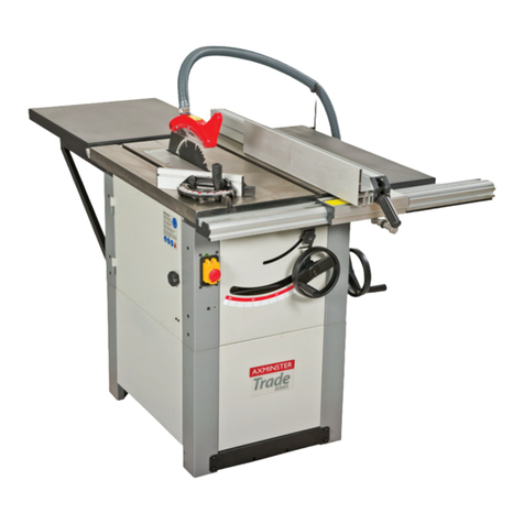
Axminster Trade AT254LTS User manual

AT254LTS
254mm Table Saw
Code 105573
Original Instructions
AT&M: 01/05/2019
BOOK REF : 106214

Cert No:
Axminster Tools & Machinery Ltd
Axminster Devon
EX13 5PH UK
axminster.co.uk
Type Table Saw
Model AT254LTS and conforms to the machinery example for which the
EC Type-Examination Certificate No BM 50416470
has been issued by Harvey Industries Co., Ltd.
at: 01 Building, No.68 Suyuan Road, Jiangning Economic & Technological Development Zone,
Nanjing 211100 China (Mainland)
and complies with the relevant essential health and safety requirements.
2006/42/EC
2014/35/EU
EN 1870-19:2013
EN 60204-1:2006+A1+AC
declares that the machinery described:-
This machine complies with the following directives:
EU Declaration of Conformity
06/42/EC - Annex I/05.2006
Signed
Andrew Parkhouse
Operations Director Date: 29/08/2018

Please Save This Manual For Future Reference - 3 -
TABLE OF CONTENTS
INTRODUCTION
SECTION 1 SAFETY INFORMATION------------------------------------------------------4
SECTION 2 ELECTRICAL REQUIREMENTS------------------------------------------12
SECTION 3 PRODUCT SPECIFICATIONS --------------------------------------------13
SECTION 4 FEATURE IDENTIFICATION -----------------------------------------------14
SECTION 5 UNPACKING & INVENTORY-----------------------------------------------15
SECTION 6 ASSEMBLY----------------------------------------------------------------------16
SECTION 7 ADJUSTMENTS---------------------------------------------------------------21
SECTION 8 OPERATIONS------------------------------------------------------------------24
SECTION 9 SAFETY ACCESSORIES---------------------------------------------------26
SECTION 10 MAINTENANCE---------------------------------------------------------------27
SECTION 11 TROUBLE SHOOTING GUIDE--------------------------------------------28
SECTION 12 WIRING DIAGRAM-----------------------------------------------------------29
SECTION 13 PARTS LIST---------------------------------------------------------------------30
SECTION 14 WARRANTY INFORMATION-----------------------------------------------40

- 4 - Please Save This Manual For Future Reference
SAFETY RULES
FOR YOUR OWN SAFETY, READ INSTRUCTION
MANUAL BEFORE OPERATING THIS MACHINE.
The purpose of safety symbols is to attract your attention to possible hazardous conditions.
This manual uses a series of symbols and signal words intended to convey the level of importance
of the safety messages. The progression of symbols is described below. Remember that safety
messages by themselves do not eliminate danger and are not a substitute for proper accident
prevention measures.
DANGER indicates an imminently hazardous situation which, if not
avoided, WILL result in death or serious injury.
WARNING indicates a potentially hazardous situation which, if not
avoided, COULD result in death or serious injury.
CAUTION indicates a potentially hazardous situation which, if not
avoided, MAY result in minor or moderate injury. It may also be used
to address practices not related to personal injury.
This symbol is used to alert the user to useful information about
proper operation of the machine.
GENERAL SAFETY INSTRUCTIONS FOR MACHINERY
1. KNOW YOUR MACHINE. Read and understand the owner’s manual and labels affixed to the machine. Learn its
application and limitations as well as it’s specific potential hazards.
2. GROUNDING THE MACHINE. Electrocution, fire, or equipment damage may occur if machine is not correctly
grounded and connected to the power supply.
3. KEEP WORK AREA SAFETY. Keep work area clean and well lit. Cluttered or dark areas invite accidents.
4. KEEP CHILDREN AND BYSTANDERS AWAY WHILE OPERATING THE MACHIE. Distractions can cause you
to lose control. All visitors should be kept safe distance from work area.
5. MAKE WORKSHOP CHILD PROOF. Untrained operators have a higher risk of being hurt or killed. Only allow
trained/supervised people to use this machine. Children or untrained people may be seriously injured by this machine.
Only install in an access restricted location.
6. DISCONNECT POWER FIRST. Always disconnect machine from power supply BEFORE making adjustments,
changing tooling, or servicing machine. This prevents an injury risk from unintended startup or contact with live
electrical components.
7. ELECTRICAL EQUIPMENT INJURY RISKS. You can be shocked, burned, or killed by touching live electrical
components or improperly grounded machinery. To reduce this risk, only allow qualified service personnel to do
electrical installation or repair work, and always disconnect power before accessing or exposing electrical equipment.
8. AVOID DANGEROUS ENVIRONMENT. Don’t use power tools in damp or wet locations or expose them to rain.
Keep work area well lit and provide adequate surrounding work space
9. WEAR PROPER APPAREL. Do not wear loose clothing, gloves, neckties or jewelry (rings, watch) because they
could get caught in moving parts. Non-slip footwear is recommended. Wear protective hair covering to contain long
hair. Roll up long sleeves above the elbows.

Please Save This Manual For Future Reference - 5 -
10. ALWAYS WEAR SAFETY GLASSES. Everyday eyeglasses only have impact resistant lenses, there are NOT
safety glasses. Also use a face or dust mask if cutting operation is dusty.
11. HEARING PROTECTION. Always wear hearing protection when operating or observing loud machinery.
Extended exposure to this noise without hearing protection can cause permanent hearing loss.
12. GUARDS & COVERS. Guards and covers reduce accidental contact with moving parts or flying debris. Make
sure they are properly installed, undamaged, and working correctly BEFORE operating machine.
13. REMOVE ADJUSTING KEYS AND WRENCHES. Form habit of checking to see that keys and adjusting
wrenches are removed from machine before turning it on.
14. DON’T OVERREACH. Keep proper footing and balance at all times when operating machine. Avoid awkward
hand positions that make workpiece control difficult or increase the risk of accidental injury.
.
15. MAINTAIN TOOL WITH CARE. Keep tools sharp and clean for best and safest performance. Follow instructions
for lubricating and changing accessories.
16. AVOID ACCIDENTAL STARTING. Make sure the switch is in the ‘’OFF’’ position before plugging in.
17. USE RIGHT TOOL. Don’t force the tool or the attachment to do a job for which it was not designed.
18. USE RECOMMENDED ACCESSORIES. Consult the manual for recommended accessories. Follow the
instructions that accompany the accessories. The use of improper accessories may cause hazards.
19. NEVER STAND ON TOOL. Serious injury could occur if the tool tip over. Do not store materials to stand on the
tool to reach them.
20. CHECK DAMAGED PARTS. Before further use of the tool, a guard or other parts that are damaged should be
carefully checked to ensure that they will operate properly and perform their intended function. Check for alignment of
moving parts, breakage of parts, mounting, and any other conditions that may affect its operation. A guard or other
parts that are damaged should be properly repaired or replaced.
21. NEVER LEAVE MACHINE RUNNING UNATTENDED. Turn power ‘’OFF’’. Don’t leave any tool running until it
comes to a complete stop.
SPECIFIC SAFETY INSTRUCTIONS FOR TABLE SAWS
1. ALWAYS USE A GUARD. Always use a guard, splitter and anti-kickback fingers on all “thru-sawing” operations.
Thru-sawing operations are those when the blade cuts completely through the workpiece as in ripping or
crosscutting.
2. ALWAYS HOLD THE WORK. Always hold the work firmly against the miter gauge or fence.
3. ALWAYS USE A PUSHSTICK. For ripping narrow stock. Refer to ripping applications in manual where push sticks
are covered in detail.
4.NEVER. Never perform any operations “free-hand” which means using your hands to support or guide the
workpiece. Always use either the fence or the miter gauge to position and guide the workpiece.
5.NEVER. Never stand or have any part of your body in line with the path of the saw blade.
6.NEVER REACH BEHIND. Never reach behind or over the cutting tool with either hand for any reason.
7. MOVE THE RIP FENCE. Move the rip fence out of the way when crosscutting.
8. WHEN CUTTING MOULDINGS. Never run the stock between the fence and the moulding cutter-head. Refer to
moulding applications in the accessory manual for details.
9. DIRECTION OF FEED. Feed work into the blade against the direction of rotation.
10. NEVER. Never use the fence as a cut-off gauge when you are cross-cutting.
11. NEVER. Never attempt to free a stalled saw blade without first turning the saw OFF.

- 6 - Please Save This Manual For Future Reference
12. PROVIDE ADEQUATE SUPPORT. To the rear and sides of the table saw for wide or long workpieces.
13. AVOID KICKBACKS. Avoid kickbacks (work thrown back towards you) by keeping the blade sharp, by keeping
the rip fence parallel to the saw blade, by keeping the splitter and anti-kickback fingers and guard in place and
operating, by not releasing work before it is pushed all the way past the saw blade, and by not ripping work that is
twisted or warped or does not have a straight edge to guide along the fence.
14. AVOID AWKWARD OPERATIONS. Avoid awkward operations and hand positions where a sudden slip could
cause your hand to move into the spinning blade.
PROTECTING YOURSELF FROM KICKBACK. Even if you know how to prevent kickback, it may still happen. Here
are some ways to protect yourself if kickback DOES occur
:• Stand to the side of the blade during every cut. If kickback does occur, the thrown workpiece usually travels directly
in front of the blade.
• Wear safety glasses or a face shield. In the event of kickback, your eyes and face are the most vulnerable parts of
your body.
• Never, for any reason, place your hand behind the blade. Should kickback occur, your hand will be pulled into the
blade, which could cause amputation
.• Use a push stick to keep your hands farther away from the moving blade. If kickback occurs, the push stick will
most likely take the damage your hand would have received
.• Use feather boards or anti-kickback devices to assist with feeding and prevent or slow down kickback.
CAUTION: Statistics show that most common accidents among table saw users can be linked to
kickback. Kickback is typically defined as the high-speed expulsion of stock from the table saw toward its
operator. In addition to the danger of the operator or others in the area being struck by the flying stock, it is
often the case that the operator’s hands are pulled into the blade during kickback.
The protection of people against electrical shock due to indirect contacts should be normally ensured by
automatic isolation of the electrical power supply of the machine by the operation of a protective device
installed by the user in the line powering the machine;
WARNING!
Safety is the most important consideration in the operation this equipment. The following instructive.
IN GENERAL
The machine is designed to cut solid wood, chipboard, fireboard, plywood and also these materials where they are
covered with plastic laminate. The machine is not designed to cut meat, metal material, log wood.
This machine is provided with various safety equipment protecting the operator and the machine as well. This,
however, cannot involve all safety aspects. Therefore the operator must read through and understand this chapter .
He must moreover respect also other aspects of danger, referring to surroundings conditions and processed
materials.
This manual takes in 3 categories of instructive safety symbols:
Appeal recommending to proceed entirely according to following instructions. A
dispatch or operator's heavy injury impends in case of non-performing this regulation.
Warning against improper techniques or machine using ways, those can endanger
human health, machine functioning, environment or cause economic worse.
Caution is an appeal to appropriate care during practicing of following activities.

Please Save This Manual For Future Reference - 7 -
Nonperformance of this caution can cause a small sized injury or machine damage.
Basic safety requirements
Never touch the low voltage system on the electric control panels, motors and
terminal boards. Every of mentioned unit is indicated with a shield.
-Before connecting machine to mains: Make sure that all safety parts are in active position and check up their
functioning. Incase of necessary removing doors or protecting coverings unplug the plug from mains socket.
-When door or protecting covering are apart-Do not connect the machine to the mains.
To avoid incorrect operating
-Learn positions of switches before machine starting.
-Avoid touching some switches by chance on running machine.
-Never touch rotating tool by hands or somewhat else.
-When you will not work on at the machine-switch it off by control panel switch and unplug it from the mains socket.
-Before cleaning: Switch off the machine and unplug it from socket.
-Before doing maintenance inside machine: Always switch it off and disconnect plug from mains socket.
-When more workers operate the machine-do not begin another work not having informed other worker about your
intention how you will run on.
-Do not do up the machine in any way able to endanger its safe operating.
-In doubts about correctness of technique –contact a responsible person.
WARNING!
Safety is the most important consideration in the operation of this equipment. The following instructions must be
followed at all times.
-Do not neglect practicing of regular inspections in tune with ser-vice manual
instructions.
-Check up and make sure that nothing troublesome occurs on the machine.
-After finishing of work adjust the machine so as to be ready for following operations.
In case of mains outage - stop the machine immediately, and unplug the plug from socket.
-Do not over-paint, wear, damage, do up nor get off safety shields. If they get unreadable or lost-contact production
plant and renew them.
Working dress and personal safety
-Experience shows that various personally worn objects e.g. finger rings, watches,
wristbands and the like used to cause injuries.
-Hence put them away before beginning of work, fasten sleeves,
remove tie-those could be caught by various parts of working machines. Brace your hair so as not to fly free and wear
suitable shoes recommended or rated by working safety rules of a country in question.
-Wear safety outfit (glasses, apron, safety footwear and the like).
-In case of obstacles above your head in working space- wear a helmet.
-Wear always a protecting mask during sawing material- source of dust (when sawing).
-Never wear free working dress.
-Never work on the machine under influence of drugs or spirit drinks.
-If you suffer from staggers, fade or swoon - do not work on the machine.

- 8 - Please Save This Manual For Future Reference
Safety regulations for machine operator
-Do not start up the machine before having got up the content of this manual.
-Check up whether electric cables are not damaged so as an electric current fading would not cause an injury
(electric shock).
-Check up regularly whether safety coverings are properly mounted and if they are undamaged.
-Damaged coverings repair immediately or replace with other ones.
-Do not start the machine with removed protecting covering.
-Never use deformed or cracked tools.
-Replace blunt tools as soon as possible, for blunt tools often cause injuries or damages.
-Never use tools at higher speed than recommended by its producer.
-Stop all machine functions before replacing of tools.
-Do not remove in any else interfere to safety elements like coverings, interlocking switches, nor practice its mutual
blockage.
-Require an assistance for manipulation with parts exceeding your abilities.
-At a storm we recommend: Do NOT operate at the machine.
Safety regulations for maintenance
Get up manual instruction for machine maintenance manual in all points before starting any maintenance work.
-Before beginning with maintenance works: Stop always the ma-chine and
disconnect the machine by towing off the plug form socket. Herewith you avoid
an occasional starting of machine by chance by another else person.
-A qualified person must practice maintenance works on electric parts.
-The machine is not disconnected from voltage when it gets stopped. Stop always
the machine and disconnect the machine
by towing off the plug form socket.
-Do not clean the machine or its peripheral system if machine is completely out of run as long as the machine is not
stopped and the plug towed out from the mains socket.
-Keep your fingers distant from belts and belts pulleys. Before exchange of machine electric parts -Stop always the
machine and disconnect the machine by towing off the plug form socket.
-For replacing of defected products use those consistent with specification of originals.
-Do not remove or do up blocking of interlocking switch.
-Keep always tidy the space for maintenance including your working place.
Maintenance work must be practiced by qualified personnel in turn with producer’s
instructions.
Read through all the instructions manual for maintenance manual carefully.
For an exchange of parts and needy subjects - ensure in advance equal ones with the original type or corresponding
with the norms.
-Use only specified brands of lubricant (oil or grease) or with these equal ones.
-Do not use compressed air for machine cleaning or removing of wood chips.
-Control results of maintenance in presence of a responsible person.

Please Save This Manual For Future Reference - 9 -
Safety regulations for working place
- Ensure always sufficient working space and free access to the machine and its
peripheral device.
- Place the tools and other obstacles at a place for this intended and remote from
the machine.
- Ensure sufficient lighting in working space that will not throw shadows or cause a stroboscopic effect. Hygienic
norms indicate 500 lx for minimal lighting for safe and quality work.
- Never lay tools or other subjects onto working tables or coverings.
Safety of operation
- Damaged supplying cable must be replaced immediately by a competent
specialist. Machine run with damaged supply cables is dangerous to life and
therefore forbidden.
- Before establishing the machine to the run make sure that the voltage and frequency stated on the machine rating
plate answer to those of supplying mains.
- Always stop the machine and disconnect the machine by towing off the plug form
socket. before tools adjusting and replace and adjusting, treatment and
maintenance works. Herewith you avoid an occasional starting of machine by any
else person.
Rotating direction
- An injury danger menaces at an improper rotating direction of saw band wheel!
Special Safety Warnings for Band Saw
1. Always allow the band saw blade to stop before removing scrap pieces from table.
2. Always keep hands and fingers away from the blade.
3. Never attempt to saw stock that does not have a flat surface, unless a suitable support is used.
4. Always hold material firmly and feed it into the blade at a moderate speed.
5. Always turn off the machine if the material is to be backed out of an uncompleted out.
6. Adjust the upper guide about “1/8” above the material being cut.
7. Check for proper blade size and type for thickness and type of material being cut.
8. Make sure that the blade tension and blade tracking are properly adjusted.
9. Make “relief” cuts before cutting long curves.
10. Release blade tension when the saw will not be used for a long period of time.
Safety Sign on The Machine
For your safety, signs are attached to the machine warning specific dangers or providing special
information!
Please keep the signs on the machine clean so that they are always legible. Also replace damaged or
missing signs immediately .In some of our operating manuals, important signs are pictured as shown in the
following examples. They may deviate from one another in the type of depiction although they are equivalent
in the meanings!

- 10 - Please Save This Manual For Future Reference
Refer to instruction manual/booklet
To signify that the instruction manual/ booklet must be read.
Disconnect mains plug from electrical outlet
To signify that the mains plug must be disconnected from electrical outlet in case of maintenance,
malfunction or when left unattended.
Wear opaque eye protection
To signify that opaque eye protection must be worn.
Wear ear protection
To signify that ear protection must be worn.
Wear safety footwear
To signify that safety footwear must be worn.
Warning; Electricity
To warn of a hazard from electricity.
No pushing
To prohibit pushing against an object.
No reaching in
To prohibit a person from putting hands into openings.
The position of the name plate of the machine. For the detailed information, see following name plate
sample.
b) intended use of the machine including reasonably foreseeable misuse which includes working without the saw
blade guard or the protective device for grooving in the protective position;
1) take precautions to reduce the hazard of inhalation of harmful dusts (e.g. wearing a dust mask);
2) wear ear protection to prevent hearing loss and
3) take care the hazard of cutting when handling saw blades, grooving tools, feeding wood into the machine or doing
maintenance;
4) not to try removing chips or workpieces whilst the saw blade(s) is (are) running;
5) not to try using the machine unless all of the guards and other safety devices necessary for machining are in good
working order.
Before beginning assembly, take note of the following precautions and suggestions
----- The machine is bolted to the pallet. Before attempting any of the assembly procedures remove all of the loose

Please Save This Manual For Future Reference - 11 -
parts and hardware from the inside of the machine and unbolt the machine from the pallet.
----- FLOOR: This tool distributes a large amount of weight over a small area. Make certain that the floor is capable of
supporting both the weight of the machine and the operator. The floor should also be a level surface. If the unit
wobbles or rocks once in place, be sure to eliminate by using shims.
f) take care that the machine is placed only on stable and even surfaces;
j) operators adequately trained in the use, adjustment and operation of the machine;
k) only sharpened tools manufactured in accordance with the requirements of EN 847-1:2005+A1:2007 shall be
used;
l) only milling tool for hand feed with a cutting width of less than or equal to 20 mm, marked MAN in accordance with
EN 847-1:2005 +A1:2007 shall be used;
n) no saw blade shall be used where the maximum marked speed is lower than the selected rotational speed of the
saw spindle;
p) the riving knife shall be used, set so that it reaches at least a level 2 mm below the highest point on the periphery of
the saw blade and that the gap between the riving knife and the saw blade shall be at least 3 mm and shall not
exceed 8 mm;
q) push blocks or push sticks shall be used when cutting small workpieces and in circumstances where it is
necessary to push the workpiece against the fence, Maximum cutting size: 800mm;
s) when cross-cutting round stock it is necessary to secure the workpiece against rotation by using a suitable jig or
holder and to use a suitable saw blade;
t) adequate general or localised lighting shall be provided;
w) during use the saw benches shall be connected to an external chip and dust extraction system;
NOTE External chip and dust extraction equipment with fixed installations are dealt with in EN 12779:2004+A1:
2009.
x) instruction that the dust extraction equipment is to be switched on before commencing machining;
2) when the machine is not in use, please test the brake frequency once a month.
3) brake - by functional testing to check that the machine is braked within the specified time;
The test time is 10s, the test frequency is 50Hz. If there is a problem, it will be shut down for use.
LWA = xx dB (measured value)
sound power level:92.7 dB(A)(no load)/100,7 dB(A)(load)
sound pressure level:76,7 dB(A)(no load)/84,6 dB(A)(load)
Associated uncertainty K = 4 dB
Measurement made in accordance with EN ISO 3746:2010.
"The figures quoted are emission levels and are not necessarily safe working levels. Whilst there is a correlation
between the emission and exposure levels, this cannot be used reliably to determine whether or not further
precautions are required. Factors that influence the actual level of exposure of the workforce include the
characteristics of the work room and the other sources of noise etc. i.e. the number of machines and other adjacent
processes. Also the permissible exposure level can vary from country to country. This information, however, will
enable the user of the machine to make a better evaluation of the hazard and risk."
ll) design specifications for the protective device for machines with riving knife mounted saw blade guard shall be
given: such protective device shall be made out of chip able material; of a length of 400 mm; of a dimension square to
the parallel fence of at least 200 mm.

- 12 - Please Save This Manual For Future Reference
ELECTRICAL REQUIREMENTS
GROUNDING
This cabinet hybrid saw must be grounded, if it should malfunction or breakdown, grounding provides a path of
least resistance for electric current, which reduces the risk of electric shock. To maintain proper grounding of your
table saw, do not remove or alter the grounding prong in any manner.
WARNING: If out let is not properly grounded, this cabinet hybrid saw can cause electrical shock,
particularly when used in damp locations. To avoid shock or fire, if the power cord is worn or damaged in
anyway, have it replaced immediately. Not all outlets are properly grounded. If you are not sure if your outlet is
properly grounded, have it checked by a qualified electrician.
Extension Cords
If an extension cord is necessary, make sure the cord rating is suitable for the amperage listed on the machine's
motor plate. An undersized cord will cause a drop in line voltage resulting in loss of power and overheating.
Minimum Gauge Size ...........................4mm²
Maximum Length (Shorter is Better).......12m

Please Save This Manual For Future Reference - 13 -
PRODUCT SPECIFICATIONS
Item
Specification
Product
Dimensions
Weight
175kg
Length/Width/Height
1340x1650x1200mm
Foot Print(Length/Width)
514x498mm
Electrical
Switch
Switch With Overload Protection
Motor
Type
TEFC Capacitor Start Induction
Horsepower
1.65kW, S6 40%
Voltage
230V
Phase
Single
Amps
10A
Speed
2900/min
Cycle
50HZ
Power Transfer
V-Ribbed Belt Drive
Blade Information
Maximum Blade Diameter
254mm
Riving Knife/Spreader Thickness
2.5mm
Required Blade Body Thickness
1.6-2.4mm
Required Blade Kerf Thickness
2.6-3.2mm
Maximum Width Of Dado
20mm
Blade Tilt
Left 0-45°
Arbor Size
30mm
Arbor Speed
3850 RPM
Arbor Bearings
Sealed And Permanently Lubricated
Cutting Capacity
Maximum Depth Of Cut At 90°
76mm
Maximum Depth Of Cut At 45°
53mm
Maximum Rip To Right Of Blade-Standard
795mm
Maximum Rip To Left Of Blade
43mm
Table Information
Floor To Table Height
867mm
Main Table--Length/Width/Thickness
550x800x40mm
Table Size With Extension
Wings--Length/Width
1124x800mm
Fence Information
Fence Size--Length/Height
995x75/15.3mm
Miter Gauge
Information
Miter Gauge Slot Type
T-Slot
Miter Gauge Slot Type-- Width/Height
19x9.5mm
Other Information
Paint
Power Coated
Dust Port Size
100mm

-14 - Please Save This Manual For Future Reference
FEATURE IDENTIFICATION
IDENTIFICATION
1. Rear Outfeed Table;
2. Mitre Gauge;
3. Blade Guard;
4. Fence;
5. Rear rail;
6. Right Hand Extension Table;
7. Front rail;
8. Scale;
9. Front Rail Tube;
10. Fence Lock Handle;
11. Blade Tilt Handwheel;
12. Blade Height Handwheel;
13. Handwheel Lock knob;
14. Table Tilt Scale;
15. On/Off Switch;
16. Motor cover
17. 4” Dust Port;
REMINDER: THE CONFIGURATION HERE IS FOR REFERENCE ONLY, SPECIFICATIONS ARE SUBJECT TO
THE ACTUAL PRODUCT.

Please Save This Manual For Future Reference - 15 -
UNPACKING & INVENTORY
WARNING: This machine and its components are very heavy. Get lifting help or use power lifting
equipment such as a forklift to move heavy items.
WARNING: SUFFOCATION HAZARD! Immediately discard all plastic bags and packing materials to
eliminate choking/suffocation hazards for children and animals.
The following is a description of the main components shipped each model.
A. Main Table Saw Unit........................................1
B. Right Hand Extenion Table.............................1
C. Motor Cover......................................................1
D. Riving Knife......................................................1
E. Blade Guard Assembly....................................1
F. Push Stick........................................................1
G. Miter Gauge......................................................1
H. Hex Wrench Set 2.5-8......................................1
I. Arobr Flange....................................................1 Main Table Saw Unit Side Extension Table
J. Wrench 13/27mm.............................................1
K. Dado Table Insert.............................................1
L. Hand Wheel......................................................2
M. Rear Rail...........................................................1
N. Front Rail Tube................................................1
O. Fence Assembly..............................................1
P. Front Rail..........................................................1
Q. Rear Outfeed Table.........................................1
Motor Cover Blade Guard & Riving Knife
Component Inventory
Rear Outfeed Table
Fence & Rails
NOTICE: THE CONFIGURATION HERE IS FOR REFERENCE ONLY, SPECIFICATIONS ARE
SUBJECT TO THE ACTUAL PRODUCT.
O
M
N
P

-16 - Please Save This Manual For Future Reference
ASSEMBLY
Motor Cover
Install the door by inserting the pins of the door into the two
hinge socket on the cabinet.
(See Figure 1)
Extension Table
1. Attach a right hand extension table to the right or left side
of the table using three each Hex Head Bolt 10 x 25mm,
10mm lock washers and 10mm flat washers. Have an
assistant
hold the extension wing up to the table while inserting the
screws and washers. Finger-tighten only.
(See Figure 2)
Note: If an assistant is not available, hold the wing in vertical
position up to the saw table, insert the middle screw and lock
washer finger tight, then pivot the wing to level position.
Insert the other two screws and washers finger tight.
2. Place the straightedge across the extension wings and
main table to make sure that the table surface is flat;
3. If the outside end of extension wings tilts down or up, use
a strip of masking tape to shim the extension wing up or
down ;(See Figure 3 and Figure 4)
Note: Inspect the extension wings and main table mating
surfaces for burrs or foreign materials that may inhibit
assembly. The mating edges of the wings and the table
must be clean and smootht. Use a wire brush or file if
necessary to clean up the edges.
Handwheel & Handle
Install each of the handles into the Blade Tilt & Height
handwheel and tighten with a 14mm wrench, thread the lock
knob into the center of the handwheel and tighten.
(See Figure 5)
Figure 1: Motor Cover Install
Figure 2: Extension Wings Install
Figure 3: Masking Tape Location For
Tilting The Extension Wing Up.
Figure 4: Masking Tape Location For
Tilting The Extension Wing Down
Figure 5: Handwheel Install
Lock Knob
Handle

Rails, tables and fence.
1. Install the front rail using 8mm countersunk
bolts, washers and nuts.Tighten the bolts
just enough to hold the rail, you will need to
adjust the rail height later in the process.
2. Install the rear rail using 8mm Hex socket
bolts, washers and nuts. Again, do not
tighten fully.
3. Install the fence mounting rail to the front
rail using 5 x 5mm Hex socket bolts and
washers.
4. Install the switch box using two Hex bolts
and washers to the underside of the front
fence rail.
5. Fit the support leg to the rear of the out feed
table using M8 bolts, nuts and washers.
6. Offer up the rear outfeed table to the rear
rail, aligning with the threaded holes from
underneath.
7. Insert the 5mm Hex socket bolts with
washers from underneath, tighten securely.
8. Install the RH side extension table
between the front and rear rails, using the
countersunk bolts on the front, and Hex
socket bolts on the rear. Align the table
surface with the cast iron main table so that
they are as level as possible, then tighten
fully the front and rear rail mounting bolts.
- 17-

9. Mount the rip fence to the front rail, and by using the adjusting screws “A”set the fence to be just above the main table body, and“B”to set the
fence parallel to the blade.
10. Use this adjustment to set the fence rail
parallel to the main table.There is an access
hole in the top of the fence for the hex key.
11. The rip fence can be mounted in two ways,
loosen the three hand knobs on the rear of
the fence, slide the rail off the three plates
and re-fit to suit the task.
- 18-

Please Save This Manual For Future Reference - 19-
Fence
Place the Fence on the rails on the right hand side of the
blade.
(See Figure 6 )
Note: The cam foot must contacts the cam on the fence lock
handle before you place the fence on the rail, otherwise the
fence will not lock onto the rail tube.
Miter Gauge
Slide the miter gauge into the T-slot on the left hand side of
the blade.
(See Figure 7)
Figure 6: Fence Installed On Rail
Figure 7: Miter Gauge Attached

- 20 - Please Save This Manual For Future Reference
Magnetic Switch
Install the magnetic switch onto the bottom left hand side of
the front rail using two M5-.8x 8 hex bolts, 5mm lock
washers, and 5mmflat washers.
(See Figure 8)
Saw Blade
1. Remove blade guard assembly and table insert.
2. Unlock the raise/lower handwheel lock knob and raise
saw blade to maximum height.
3. Depress locking pin (See Figure 9) and slowly rotate
blade toward you until pin engages into arbor. Hold arbor in
locked position.
4. Place supplied open-end wrench (A) on the arbor nut
(B).Turn wrench counterclockwise to loosen nut. Remove
arbor nut, blade flange (C) and saw blade (D).
(See Figure 10)
5. Place new blade on arbor. MAKE SURE saw blade teeth
point down at the front side of saw table. Place flange and
nut on arbor and securely snug blade in position.
6. Replace the blade guard assembly & table insert.
WARNING: Turn the power switch “OFF” and
unplug the power cord from its power source when
changing the saw blade.
Checking Fence Parallelism
Sliding the fence along the rails , if it drags across the table,
then adjust the rear rail foot(See Figure 11) to raise the
fence off of the table just enough , so that the gap between
the fence and the table is even from front to back;
Slide the fence up, against the right hand edge of the miter
slot and lock it in place. Examine how the fence line up with
the miter slot
(See Figure 12)
Back of the fence to pivot outward not more than 1⁄64" from
being parallel to the blade is permissible. This creates a
slightly larger opening between the fence and the blade, at
the rear of the blade, to reduce the risk of workpiece binding
or burning as it is fed through the cut. Many woodworkers
intentionally set up their fence in this manner. Keep this in
mind before adjusting your fence.
- If the fence/miter slot are still parallel with the blade,
proceed to Fence Scale.
- If the fence is not parallel to the blade/miter slot, then you
MUST adjust the fence as Page 16.
Figure 8: Magnetic Switch Installed
Figure 9: Locking Pin Position
Figure 10: Securing Blade
Figure 11: Rip Fence
Figure 12: Checking Fence Parallelism
Table of contents
Other Axminster Trade Saw manuals

Axminster Trade
Axminster Trade PS315 User manual

Axminster Trade
Axminster Trade AT254SB User manual

Axminster Trade
Axminster Trade AT305SB User manual

Axminster Trade
Axminster Trade AT3352B User manual

Axminster Trade
Axminster Trade AT2552B User manual

Axminster Trade
Axminster Trade AW10BSB2 User manual

Axminster Trade
Axminster Trade AT1854B User manual

Axminster Trade
Axminster Trade AT460SS User manual

Axminster Trade
Axminster Trade AT3086B User manual

Axminster Trade
Axminster Trade AT254PS13 User manual