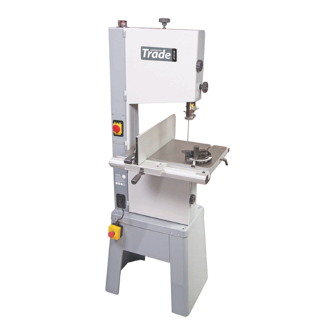
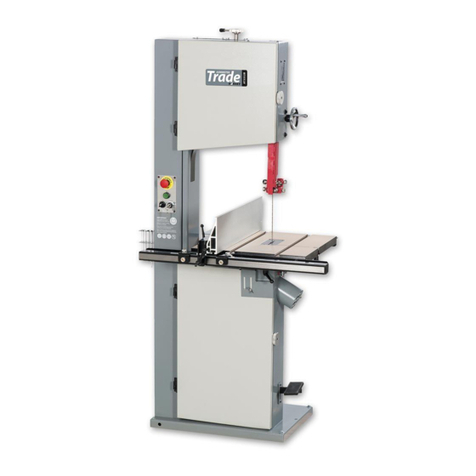
Axminster Trade AT3086B User manual

AT3086B
Bandsaw
Code 103472
Original Instructions
AT: 14/09/2020
BOOK REF: 103822
BOOK VERSION: 04

Index of Contents
2
EU Declaration of Conformity
EU Declaration of Conformity 02
What’s Included 03-04-05
General Instructions for 230V Machines 06
Specification 07
Main Assembly 07-08-09-10-11-12
Machine Dimensions 13
Illustration and Parts Description 14-15-16-17-18-19
Setting Up the Saw 20-21-22-23-24-25
Operating Instructions 25-26-27
Electro-magnetic Motor Brake Switch 28
Compact Mitre Fence 29
Changing the Saw Blade 30-31
Maintenance 32-33
Bandsaw Blade Information 34-35
Bandsaw Trouble Shooting/Accessories 36
UJK Technology Bandsaw Buddy 37
Exploded Diagrams/Lists 38-39-40-41-42-43-44-45-46-47
Wiring Diagram 48
Notes 49-50-51
The symbols below advise the correct safety procedures when using this machine.
Fully read manual
and safety instructions
before use
Eye protection
should be worn
Ear protection
should be worn
HAZARD
Dust mask
should be worn
Cert No: SBW-350H
Axminster Tool Centre Ltd
Axminster Devon
EX13 5PH UK
axminstertoos.com
Type Bandsaw
Model AT3086B conforms to the machinery example for which the
EC Type-Examination Certificate No BM50309398
has been issued by OAV Equipment & Tools, Inc.
at: No. 96,Wucuo 1st St., 43641 Qingshui Dist., Taichung City,Taiwan, R.O.C
and complies with the relevant essential health and safety requirements.
2006/42/EC
06/42/EC - Annex I/05.2006
EN 1807-1:2013
declares that the machinery described:-
This machine complies with the following directives:
EU Declaration of Conformity
Signed
Andrew Parkhouse
Operations Director Date: 26/04/2020

What’s Included
3
Please read the Instruction Manual prior to using your new machine; as well as the operating procedures for your new
machine, there are numerous hints and tips to help you to use the machine safely and to maintain its efficiency and prolong its
life. Keep this Instruction Manual readily accessible for any others who may also be required to use the machine.
1
Quantity Item Model Number
AT3086B
1 Trade Bandsaw
1 Blade 3,086.1mm (121.5”) long, mounted on saw but not tensioned.
1 Cast Iron Table 1
Fence Assembly: Bags Comprising:
1 Front Fence Rail with Scale 21 Mitre Fence Assembly 12
1 Fence 3a) Threaded lever with washer
1 Fence Clamp Assembly with b) Two Grub screws
Magnifying Glass 4c) Two Hex Keys 3-4mm
1 M8 Threaded Lever 5d) Mitre Fence Body
1 M8 Lift and Shift Handle 6e) Threaded‘T’ bolts with Clamping Knobs
1 Threaded ‘T’ Slot Insert 7f) Aluminium Fence
2 M6 x 20mm Threaded Bolts 8g) Depth Stop Assembly
1 M8 Large Washer 9
2 M6 Small Washers 10 1 Table Alignment Pin Handle 13
1 M8 Nut 11 1 10-13mm Spanner 14
1 4-5-8mm Hex Keys 15
4 M8 Washers 16
4 M8 Spring Washers 17
4 M8 x 16mm Threaded Bolts 18
1 Fence Assembly Support bracket 19
1 User Manual 2 M6 Cap head screws with washers 20
1 Large Washer and Nut
(for Table Alignment Pin Handle) 21
HAVING UNPACKED YOUR ACCESSORIES PLEASE
DISPOSE OF ANY UNWANTED PACKAGING
PROPERLY. THE POLYTHENE AND CARD ARE
RECYCLABLE.

2
3
4
What’s Included
4
7
56
10 9
8
11

What’s Included
5
12
13
14
18
19
20 21
15
16
17
a
b
d
c
e
f
g

General Instructions for 230V Machines
6
The following will enable you to observe good working
practices, keep yourself and fellow workers safe and maintain
your tools and equipment in good working order.
WARNING!! KEEP TOOLS AND EQUIPMENT
OUT OF REACH OF YOUNG CHILDREN
Mains Powered Tools
• Tools are supplied with an attached 16 Amp UK plug.
• Inspect the cable and plug to ensure that neither are
damaged. Repair if necessary by a suitably qualified person.
• Do not use when or where it is liable to get wet.
Workplace
• Do not use 230V a.c. powered tools anywhere
within a site area that is flooded.
• Keep machine clean.
• Leave machine unplugged until work is about to
commence.
• Always disconnect by pulling on the plug body
and not the cable.
KEEP WORK AREA AS UNCLUTTERED AS IS PRACTICAL.
UNDER NO CIRCUMSTANCES SHOULD CHILDREN BE
ALLOWED IN WORK AREAS.
•Carry out a final check e.g. check the cutting tool
is securely tightened in the machine and the correct
speed and function set.
•Ensure you are comfortable before you start work,
balanced, not reaching etc.
•Wear appropriate safety clothing, goggles, gloves,
masks etc.Wear ear defenders at all times.
•If you have long hair wear a hair net or helmet to
prevent it
being caught up in the rotating parts of the machine.
•Consideration should be given to the removal of rings and
wristwatches.
•Consideration should also be given to non-slip
footwear etc.
•If another person is to use the machine, ensure they are
suitably qualified to use it.
•Do not use the machine if you are tired or distracted
•Do not use this machine within the designated safety areas
of flammable liquid stores or in areas where there may be
volatile gases.
•Check cutters are correct type and size, are undamaged
and are kept clean and sharp, this will maintain their
operating performance and lessen the loading on the
machine.
•OBSERVE…. make sure you know what is happening
around you and USE YOUR COMMON SENSE.
Specification
7
Code 103472
Model AT3086B
Rating Trade
Power 1.5kW 230V 50Hz 1ph 16A
Blade Speed 720 m/min
Blade Length 3086.1 mm
Blade Width Min/Max 3-19 mm
Max Width of Cut 342 mm without fence
Max Depth of Cut 356 mm
Max Width of Cut with Fence 315 mm
Noise Level 85 dB
Table Size 552 x 410 mm
Table Height 940 mm
Wheel Diameter 355 mm
Dust Extraction Outlet 100 mm x 2
Overall L x W x H 740 x 825 x 1,921 mm
Weight 145 kg
Main Assembly
Your bandsaw is 95% assembled in order to reduce the
footprint of the machine for packaging, several items are
dismounted from the machine and need to be re-affixed.
WARNING! THE BANDSAW IS A HEAVY PIECE
OF MACHINERY,WE STRONGLY ADVISE YOU GET
THE ASSISTANCE OF ANOTHER PERSON OR USE
SOME SORT OF LIFTING DEVICE, (HOIST, ENGINE
CRANE), BEFORE YOU ATTEMPT TO LIFT OR MOVE
THIS MACHINE!
Mounting the Table
The saw table can be fitted without removing the blade.
However, if you would feel more comfortable not having to
manoeuvre the table around the blade (the table is quite
heavy), remove the blade by opening the top and bottom
covers, release the tension on the blade by releasing the
Quick release tensioning lever (A), see fig 01-02-03.
Remove the protective rapping around the bandsaw
blade, see fig B. CAUTION! take care, the blade is sharp.
Lift the bandsaw off the pallet using the ‘Eye Bolt Lifting Ring’
mounted to the top of the bandsaw. Place the saw on a flat
surface, ascertain the orientation of the machine and move it
to its desired position in the workshop. Ensure that the machine
is positioned to allow sufficient clearance all round to cater for
the maximum length of timber you wish to cut.
Fig 01-02-03
A
Continues Over....
B
Eye bolt lifting ring

Main Assembly
8
Fig 04-05
Fig 06-07-08
1
Table insert Table shipment bolt
Tilt quadrant
Pre-drilled hole
Fig 09-10
16 17
18
Fig 11-12
Table recess
Machined hole
Insert pin
Step 1 Remove the table insert and the table shipment
cap head bolt and nut and place aside, see figs 04-05. Lift the
table (1), slide the blade through the table slot, rotate the table
round and lower the table on to the tilt quadrant assembly, see
fig 06-07. Line up threaded holes with the pre-drilled holes in
the tilt quadrant, see fig 08.
Step 2 Place a spring/washer (16 -17) over each M8 threaded
bolt (18), see fig 09 and lightly tighten the four bolts in position,
see fig 10. Note DON’T FULLY TIGHTEN at this point.
Step 3 Replace the table insert by lining up the two pins in
the insert with the machined holes in the recess to the centre
of the cast iron table. Push firmly down, see figs 11-12.
14

Main Assembly
9
Continues Over....
Step 5 Place a straight edge or 90˚ square across the table’s
slot, adjust the tapered alignment pin handle (13) beneath the
table, this will align both sides of the table.
Checking both sides of the table are level
Fence Assembly
Locate the front fence rail with scale (2), fence (3), fence clamp
assembly (4), M8 lift & shift handle (6), M8 threaded lever (5),
threaded ‘T’slot insert (7), M6x20mm bolts (8), M8 large
washers (9), M6 small washers (10) and M8 nut (11).
Step 1 Place a spring/washer (9-10) over each M6x20mm bolt
(8), line up the elongated holes in the front fence rail (2) with
the pre-drilled holes to the front of the cast iron table (1),
introduce the two M6x20mm bolts (8) through the fence rail
and lightly tighten using the supplied spanner (14), see figs
15-16-17.
Step 2 Fit the fence clamp assembly (4) over the front fence rail
(2) and lower the assembly on the cast iron table, see fig 18.
Fig 15-16-17
2
2
8
Fig 18
4
2
Step 3 Locate the M8 nut (11), and screw it onto the thread
of the M8 threaded lever (5) then screw the threaded lever (5)
into the threaded hole in the clamp assembly (4) mechanism
and tighten the nut with a spanner, see figs 19-20.
Step 4 Locate the table alignment pin handle (13) and the
large washer and nut (21). Insert the washer over the thread
and screw on the nut, giving sufficient clearance between
washer and nut, see fig 13. Insert the threaded handle into the
slot in the cast iron table (1) and tighten so the nut clamps
down in the machined recess, see fig 14.
Fig 13-14
1321
Machined recess
814
10
9
Fig 19-20
5
11
4

Main Assembly
10
Spanner
Step 4 Locate the fence (3), M8 lift and shift handle/ M8
large washer (6) and threaded‘T’ slot insert (7). Place the large
washer over the thread of the lift and shift handle (6), introduce
the handle through the machined hole to the side of the cast
iron mounting on the clamping assembly (4) and lightly screw
on the threaded ‘T’slot insert (7), see fig 21.
Step 5 Introduce the ‘T’ slot to the side of the fence (3) over the
threaded ‘T’slot insert (7) and slide on the fence until the fence
(3) is flush with the rear of the cast iron table (1).Tighten the lift
and shift handle (6) to secure the fence in position, see fig 22-23.
NOTE: The fence (3) has two positions, vertical and
horizontal for cutting narrow pieces, see fig 24-25-26.
Fig 24-25-26
Fig 21
Fig 22-23
6
7
3
‘T’ slot

Main Assembly
11
Continues Over....
Mitre Fence Assembly
Fence Assembly Support Bracket
The bracket helps to support the fence assembly when the
fence is in position up against the saw frame to utilise the
maximum width of the table (1)
Locate the fence assembly support bracket (19) and the two
M6 cap head screws (20). Line up the two pre-drilled holes in
the support bracket with tapped holes to the left side of the
cast iron table (1) and using the supplied Hex key secure the
bracket (19) in position, see fig 27-28-29.
Fig 27-28-29
Using the fence clamp assembly (4) as a level, tighten the two
cap head screws (20) to secure the bracket (19) in position.
19
20
Hex key
Step 1 Locate the following parts (see page 3) Threaded lever
with washer (a), Grub screws (b), Hex keys (c), Mitre fence body
(d),Threaded ‘T’bolts with clamping knobs (e), Aluminium fence
(f) and Depth stop (g).
Step 2 Screw the lever (a) through the elongated machined
cutout in the mitre fence body (d) and into the threaded hole in
the square steel bar. Lightly tighten, see fig 30.
Step 3 Introduce the ‘T’ bolts (e) through the two pre-drilled
holes in the mitre fence mounting bracket and screw on the
two clamping knobs, see fig 31. NOTE: Give adequate clearance
on the threads for the next step.
Fig 30
Fig 31
Fig 32-33
Step 4 Introduce the ‘T’ slot to the side of the fence (f) over
each threaded ‘T’ bolt (e) lightly tighten clamping knobs to
secure the fence (f) in position, see fig 32-33. NOTE: Make sure
the fence is in the correct way round, the base of the fence
should be flush with the cast iron table (1).
f
e
a
d
e
Clamping knob

Main Assembly
12
Step 5 Locate the depth stop assembly (g), loosen the butterfly
clamping knob on top of the unit. Line up the threaded ‘T’ bolt
with the ‘T’ slot to the top of the aluminium fence (f) and slide
on the assembly. Light tighten the butterfly knob to secure the
unit in position, see fig 34-35.
Fig 34-35
Step 6 Using the supplied Hex key (c) screw the two grub
screws (b) into threaded holes to the end of the steel bar, see
fig 36-37. The grub screws can be adjusted so the mitre fence
runs smoothly in the bandsaw tables ‘T’Slot.
Fig 36-37
Step 7 Slide the mitre fence assembly into the cast iron table’s
‘T’ slot, adjust the aluminium fence (f) so it just misses the saw
blade, see fig 38.
Fig 38
g
f
‘T’ Slot ‘T’ Slot
Butterfly knob
Grub screw

Machine Dimensions
13
Code: 103472 AT2086B Bandsaw
740mm
1,921mm
0
1 2
825mm

Illustration and Parts Description
14
Upper door locking knob
Blade tracking window
Upper blade guide
adjusting wheel
Upper blade guide and guard
Upper blade guide
Fence guide rail
Dust extraction outlet
Lower wheel door
Storage locker
Table alignment Handle
Mitre fence
Lower door locking knob
Storage door locking knob
Main saw frame
Fence clamp handle
Key release emergency
stop switch
Selector switch
Power indicator
ON/OFF buttons with
emergency stop shroud
Upper wheel door
Wheel tensioning scale
Blade tensioning wheel
Eye bolt lifting ring
Fence

Illustration and Parts Description
15
Continues Over....
Key release emergency stop, press
the button to stop the bandsaw and
turn the key to release it
Upper blade guide height
scale and pointer
Electro-magnetic motor brake switch
Brake OFF (1), Brake ON (0), Run (2)
Blade tracking window
Fence clamp assembly (4), Mitre fence (12), Fence rail with scale (2), Fence (3) Scale magnifying glass
2
0
1
NVR switch control assembly
12
2
3
4

Illustration and Parts Description
16
Drive pulley
Storage compartment
Upper saw wheel
Saw table
Table insert
Saw blade
Drive pulley
Micro door switch
Blade tracking window
Lower saw wheel
Dust extraction outlet
Lower wheel door
Storage door
Upper wheel door Wheel tension assembly
Blade tensioning scale/pointer

Illustration and Parts Description
17
Continues Over....
Upper bearing blade guides (A)
Blade guide adjusting knob (B)
Blade guide fore and aft clamping screw (C)
Upper blade thrust bearing (A)
Clamping screw (B)
Guide assembly clamping screw (C)
Table level angle bracket
with adjustable stop
bolt for 90˚
Lower bearing blade guides (A), Blade guide adjusting knob (B),
Blade guide fore and aft clamping screw (C)
Lower wheel blade brushes
Rear thrust bearing (A), Rear thrust bearing clamping screw (B),
Lower blade guide assembly clamping screw (C)
Lower wheel brush
AB
CC
B
A
A
B
C
A
B
C

Illustration and Parts Description
18
Table levelling
angle bracket
with adjustable
stop bolt
Motor
Upper blade guide clamp
Blade tensioning wheel
Tracking control knob
Tracking control lock
Quick release
tensioning lever for
changing the blade
Dust extraction outlet
Tilt quadrant assembly

Illustration and Parts Description
19
Continues Over....
Quick release tensioning blade lever (A)
Tracking control knob (B), Locking handle (C)
Fence assembly support bracket (A)
Fence lift & shift clamping handle (B)
Blade tensioning wheel
Tilt quadrant clamping handle (A),Tilt quadrant rack and pinion adjusting handle (B),
Tilt quadrant scale (C), Lower thrust bearing adjusting knob (D)
Tilt quadrant scale pointer (A)
and adjusting screw (B)
A
C
B
A
D
CB
A
B
B
A

Setting Up the Saw
20
Checking the Table is Square
Step 1 Loosen the clamping handle beneath the table, see fig
39. Lower the table by turning the tilt quadrant rack and pinion
adjusting handle, until it’s against the stop. This is an angle
bracket to the rear of the cast iron table with an adjustable stop
bolt and lock nut, see fig 15. The head of the bolt acts as a stop
when it strikes the machine frame.
Fig 39
Step 2 Make sure the upper blade guide is raised as high as
possible. Place a square on the table and move it up against
the blade (behind the teeth), see fig 40.
Fig 40
Step 3 Check that the blade is perpendicular to the table. If
adjustment is required reset the levelling stop bolt to the rear
of the cast iron table then tighten the lock nut. Check again.
Once you are satisfied, tighten both tilt and table clamping
handle, see fig 41-42-43.
Fig 41-42-43
Step 5 Slide the fence assembly until it’s up against the blade
and press down the locking lever (5), see fig 45. Look at the
‘RED’ line on the magnifying glass to check it’s set to ‘0’ on the
scale, see fig 46. If it’s out of alignment, loosen the locking lever
(5) and tap the side of the fence rail (2) until the scale reads ‘0’
then re-secure the fence rail, see figs 47-48.
Fig 45-46-47-48
Levelling stop bolt
Tilt quadrant adjusting handle
Lock nut
90˚ Engineers square
Blade teeth
Step 4 Check that the pointer on the tilt quadrant scale reads
zero, if not, loosen the Phillips screw that holds the pointer and
adjust until correct. Re-tighten the screw and table clamping
handle, see fig 44.
Fig 44
Scale Pointer
Phillips screw
MAKE SURE THE SAW IS DISCONNECTED
FROM THE MAINS SUPPLY!
Table of contents
Other Axminster Trade Saw manuals

Axminster Trade
Axminster Trade AW10BSB2 User manual

Axminster Trade
Axminster Trade AT254PS16 User manual

Axminster Trade
Axminster Trade PS315 User manual

Axminster Trade
Axminster Trade AT460SS User manual

Axminster Trade
Axminster Trade AT3352B User manual

Axminster Trade
Axminster Trade AT406SS User manual

Axminster Trade
Axminster Trade AT406SS User manual

Axminster Trade
Axminster Trade AT1854B User manual

Axminster Trade
Axminster Trade AT2552B User manual

Axminster Trade
Axminster Trade AT254SB User manual