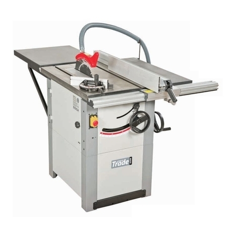
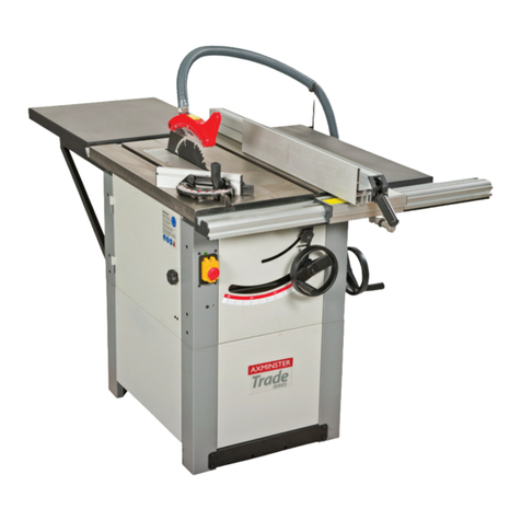
Axminster Trade AT254PS16 User manual

AT254PS16
Panel Saw
Code 105466
Original Instructions
AT: 19/08/2020
BOOK VERSION: 03

Cert No: P25
Axminster Tools & Machinery Ltd
Axminster Devon
EX13 5PH UK
axminster.co.uk
Type Panel Saw
Model AT254PS16 and conforms to the machinery example for which the
EC Type-Examination Certificate No BM 50319002
has been issued by OAV Equipment & Tools, Inc.
at: No. 96,Wucuo 1st st., 43641 Qingshui Dist.,Taichung City Taiwan
and complies with the relevant essential health and safety requirements.
2006/42/EC
06/42/EC - Annex I/05.2006
EN 1807-1:2013
declares that the machinery described:-
This machine complies with the following directives:
EU Declaration of Conformity
Signed
Andrew Parkhouse
Operations Director Date: 20/08/2021

PANEL SAW INSTRUCTION MANUAL
1
Table of Contents
General Information …………………………………………………………………………………….
2
Safety R les………………………………………………………………………………………………….
2
Wiring diagram…………………………………………………………………………………………….
3
Specification Sheet……………………………………………………………………………………….
4
Main Feat res………………………………………………………………………………………………
5
(1) Control Panel…………………………………………………………………………………….
6
(2) Rip Fence…………………………………………………………………………………………..
6
(3) Hold Down…………………………………………………………………………………………
6
(4) Riving Knife Saw Blade……………………………………………………………………
6
Assembly And Set Up……………………………………………………………………………………
6
(1) Sliding Table ……………………………………………………………………………………..
6
(2) Extension Table (large small) …………………………………………………………..
7
(3) Scale Adjustment……………………………………………………………………………….
8
(4) Rip Fence…………………………………………………………………………………………..
8
(5) Cross Table………………………………………………………………………………………..
9
(6) Cross Fence……………………………………………………………………………………….
9
(7) Main Blade…………………………………………………………………………………………
10
(8) Scoring Blade……………………………………………………………………………………..
11
(9) Fence Scale Alignment……………………………………………………………………….
12
(10) Dust Collection…………………………………………………………………………………
12
(11) Power Cord………………………………………………………………………………………
13
(12) Test Run…………………………………………………………………………………………..
13
Operation……………………………………………………………………………………………………..
14
(1) Change Main Blade…………………………………………………………………………….
14
(2) Riving Knife Adjustment……………………………………………………………………..
15
(3) Change Scoring Blade…………………………………………………………………………
15
(4) Rip Cutting…………………………………………………………………………………………
15
(5) Crosscutting……………………………………………………………………………………….
16
(6) Miter Cutting……………………………………………………………………………………..
17
(7) Lubrication………………………………………………………………………………………..
18
(8) Replace Belts……………………………………………………………………………………..
18
(9) Blade Tilt……………………………………………………………………………………………
19
(10) Sliding Table Parallel Adjustment………………………………………………………..
20
(11) Squaring Crosscut Fence to Blade……………………………………………………….
20
(12) Trouble Shooting……………………………………………………………………………….
21
PANEL SAW INSTRUCTION MANUAL
2
General information
OAV Equipment Tools, Inc. is specialized to supply full range of panel saw from 1600, 2200,
2600, 3200 to 3800mm. The outlook design of this machine is so unique with complete cast
iron bracket instead of sheet metal, enlarged outrigger and carriage, direct dust collection
outlet.
Besides of our Band Saw series, these Table Saw series are also innovative products. Please
enjoy your operation on this machine and if you have any comment to improve them, please
don’t hesitate to contact us through your agent
Safety R les
For yo r own safety, please read instr ction man al caref lly before operating.
1. To avoid dangerous working environments, do not use stationary machine tools in wet or
damp locations, keep working area clean and well-lit.
2. Wear proper apparel, no loose clothing or jewelry which can get caught in moving parts.
3. Never leave when machine is running.
4. Disconnect electrical power before tools are serviced.
5. Remove adjusting keys and wrenches before turning machine on.
6. Make sure that the keys and adjusting wrenches have been removed and all the nuts and
bolts are secured.
7. Keep guards in place and in working order.
8. Keep children and visitors away, they should keep with a safe distance from the working
area. Never leave the machine with power on.
9. Keep hands well away from blades and all moving parts. Do not clear chips and sawdust
away with hands.

PANEL SAW INSTRUCTION MANUAL
3
WIRING DIAGRAM

PANEL SAW INSTRUCTION MANUAL
4
SPECIFICATION
Model 10” PANEL SAW
Sliding table dimension 1600 X 316MM
Max. Sliding Stroke with crossc t Fence 1600mm
Max. Sliding Stroke w/o crossc t Fence 1900mm
Table Height 912mm
Table Size W/ext. Wing W: 377mm x D: 688mm (1020mm x 1193mm)
Main Saw
Max Saw Blade Dia. 254mm
Saw Blade Arbor Diameter 30mm
C tting Height at 90°,45° 80/57mm
Motor Power 2.25KW/3PH (Optional: 2.25KW/ 1PH/3.75KW/3PH)
Spindle RPM 4,000 (Motor RPM 2875)
Scoring Saw
Saw Blade Dia. 80mm
Saw Blade Arbor Diameter 20mm
C tting Height at 90°,45° 5mm/3mm
Motor Power
Spindle RPM 8,000
Ripping Width 838mm
Crossc t Width 1,380mm/2,350mm
Blade Height Adj stment Manual
Blade Tilting Adj stment Manual, 0~45
°
Electric Control System Magnetic switch
D st Collection System Main Channel 4” (100mm), Saw blade guard extract
2-1/2” (60mm)
Standard Accessories
Extruded Profile Rip fence
Sheet Metal Extension Table x2 pcs
Standard Saw Blade Guard
Standard Miter Fence, Scoring Saw Blade
Optional Accessories Main Saw Blade, Edge Shoe
Saw Blade Hose Support Plate and Hose
D e to needs of contin o s improvement, specification is s bject to change witho t prior notice

PANEL SAW INSTRUCT
ION MANUAL
5
MAIN FEATURE
1. Flip Stop: Large stopper for accurate measurements
2. Crosscut Fence: 90° and 45° quick position design for a precise crosscutting operation
3. Riving Knife: It is prevent kickback cause by the knife closing behind the blade
4. Saw Blade Guard: Fully adjustable blade maintains maximum protection around the saw blade
5. Hose Support Plate and Hose: To collect the dust chip efficiency
6. Rip Fence: For smooth and precise cutting
7. Sliding table: For smooth cutting, precise sliding table glides the work- piece through the blade
8. Control panel: Simple push button controls for operation
9. Main Saw Blade height adjusting hand wheel: Manual adjusts the height of saw blade
10.
Main Saw Blade angle adjusting hand wheel: Manual adjusts the angle of saw blade
1
2
5
3
4
6
7
8
9
10

PANEL SAW INSTRUCT
ION MANUAL
6
(1) Control Panel
1. Main Switch: Power on and power off the panel saw.
2. Emergency Stop Button disconnects power to motor.
3. Blade on Button: Starts the main saw blade and scoring saw blade.
4. Blade off Button: Stops the main saw blade and scoring saw blade.
(2) Rip Fence
1. One single lock down lever: Simple and precise to lock the fence
assembly into fence rail.
2. Micro adjust knob: Precisely adjustment.
3. Forward and backward slide lock handle: To firm the high/low profile
alum. Fence on its forward/Backward slide track.
4. Micro-adjust lock knob: secures the fence after it has been adjusted
with micro-adjustment knob.
5. Rip fence scale: Allows precise measurement of rip cutting operations.
(3) Miter Fence
1. Fine adjustment handle. (Fig. 3)
2. To hold the wood firmly.
(4) Riving Knife and saw blade
1. Riving knife: Maintains kerfs opening during cutting operations. The
purpose is crucial to prevent kickback caused by the kerfs closing
behind the blade.
2. Main saw blade: The maximum is 254mm. (Optional accessories)
3. Scoring blade: It is rotates opposite the main saw blade, the blade cores
the workpiece before the actual cutting operation is performed
preventing teat-out in laminate materials. The scoring is adjustable
forward and backward, upper and down. (Fig. 4)
Assembly and set p
(1) Sliding Table
Sliding table contents:
T-Bolt M12-1.75 x 2
Flat washer 12mm x 2
Sliding table locate plate handle x 1
Sliding table lock plate x 1
Lock washer M12 x 2
Hex nut M12 x 1.75 x2
Switch
Stand
Fig. 1
Fig. 3
Fig. 2
Fig. 4

PANEL SAW INSTRUCT
ION MANUAL
7
Button head bolt M6 x 16
Cap screw M8 x 20
Locate plate
1. Lift the sliding table up to the cabinet, with another person’s help inset
the T-bolt (Fig. 5.1) and space them apart the same distance and the
mounting bolts to the cabinet (Fig. 5.2). Lift up the sliding table again
and fit the T-bolts into the mounting holes on the cabinet. Secure the
sliding table to the cabinet with two M12x1.75 Hex nut. Inset the locate
plate into the track use two M5 x 12 Hex socket bolt to mount the main
switch. Insert another lock plate to install two side stand and fasten the
stand use 2 pcs M8 x 20 cap screws at the bolt left and ring hand sides.
(Fig. 5.3 5.4)
2. Install the end handle of the sliding table with M6 x 16L Button head
screws 2pcs, the sliding is located when the table lock is in the right
position, (Fig. 5.5) rotate the table lock 180 degree to unlock the sliding
table.
3. Install the locate plate use 4 pcs of M6 x 12 button head screws at the
two sides of sliding table.
(2) Extension Tables content
Large extension table x 1
Small extension table x 1
Hose support plate x 1
Cap screws M10-1.5 x 25 x 6pcs, Set Screw M8-1.25 x 25 x 6pcs
Hex nuts M8-1.25 x 6pcs
Lock washer 10mm x 6pcs
Flat washers 10mm x 6pcs
Hex nut M10-1.5 x1pc
How to install the extension tables
1. Thread the set screws into the 6mm holes from the inside of both
extension tables.
2. Before the tables are leveled, please do not completely tighten the
bolts in follow steps.
3. Attach the large extension table with three M10-1.5 x 25 cap screws,
lock washers and flat washers. (Fig. 6)
4. Attach the small extension table with two M10-1.5 x 25 cap screws,
lock washers and flat washers (Fig. 7).
5. Place the hose support plate to the extension table and thread
M10-1.5 x25 screws, lock washers and hex nut (Fig. 8).
6. Check the surface 0 the table with a straightedge (Fig. 9).
Fig. 5.2
Fig. 5.3
Fig. 5.4
Fig. 5.5 Fig. 6
Fig. 5.1

PANEL SAW INSTRUCT
ION MANUAL
8
(3) Scale adj stment
Loosely thread 2 pcs M6 x 16 hex screw and 1 pc M6 x 25 hex
screw with lock and flat washers through the scale and into
table. (Fig. 10)
Tight the cap screws to the extension table with M6 hex nuts.
Line the scale up with the top of the table and tighten the hex
nuts.
(4) Rip fence
Rip fence content
Rip fence x 1pc
Bracket x 1pc
Rip fence body x1pc
Screw M12-1.75 x 90 x 3pcs
Hex nut M12-1.75 x9pcs
Flat washer 12mm x 9pcs
Lock washer 12mm x3pcs
How to adjust the rip fence
1. Thread 4pcs studs into bracket.
2. Thread an M12-1.75 hex nut onto each stud and tighten the nut
against the bracket.
3. Thread and M12-1.75 hex nut and a flat washer half way onto
each stud.
4. Insert the studs into the table (Fig. 11). Tighten with an
M12-1.75 hex nut, lock washer and a flat washer on each stud.
5. Slide the rip fence body onto the bracket.
6. Thread the lock handles into the rip fence body.
7. Lock the rip fence with the handle on the right hand side of the
rip fence body. (Fig. 12)
8. Check the height of rip fence rail by sliding rip fence along the
rail and comparing the gap between the fence body and the table.
9. Adjust the height of the rip fence rail, then tighten all nuts against the table showed. (Fig. 13)
Fig. 7 Fig. 8 Fig. 9
Fig. 10
Fig.11
Fig. 12

PANEL SAW INSTRUCT
ION MANUAL
9
(5) Crossc t table
Crosscut content
1. Crosscut table x 1
2. Crosscut table brace x 1
3. T-nut M8-1.25 x 2
4. T-nut M12-1.75 x 1
5. Flat washer 12mm x 1
6. Adjustment handle M12-1.75 x 55 x1
7. Knob M8-1.25 x 50 x 2
8. Flat washer 8mm x 2
1. Thread the M12-1.75 x 55 adjustable handle with a 12mm flat
washer through the crosscut table and into a M12-1.75 T-nut (Fig.
14)
2. Secure the pivot pin to the crosscut table first, place the extension
table set on the swing arm and sliding the T-nut into the T-slot in
the sliding table. (Fig. 15.16)
3. Slide two M8-1.25 T-nuts into the crosscut table brace.
4. Align the T-nuts in the crosscut table supporter with the holes in
the crosscut table and thread the M8-1.25 x 50 knobs, with 8mm
flat washers, into the T-nuts (Fig. 17)
(6) Crossc t fence
Crosscut fence content
1. Thread the centre stud and the flat washer 8 x Ø20 into the remaining M8-1.25 T-nut.
1. Crosscut fence x 1 7. Knob M-1.25 x 1
2. Crosscut fence support plate x 1 8. T-bolt M8-1.25 x 60 x 1
3. Centre stud M8-1.25 x 10 x 1 9. Flat washer 8mm x 1
4. Flat washer 8 x Ø20 x 1 10.
Lock washer 8mm x 3
5. T-nut M8-1.25 x 5 11.
Button head screw M8-1.25 x 16 x 2
6. Knob M8-1.25 x 25 x 1 12.
Fence support plate
Fig. 13
Fig. 14
Fig. 15 Fig. 16 Fig. 17

PANEL SAW INSTRUCT
ION MANUAL
10
2. Sliding the centre stud, an M8-1.25 x 60 T-bolt and screw M8-1.25 x 25 Knob into the crosscut
fence (Fig. 18)
3. Slide the centre stud to the end with the plastic cap and tighten it in place.
4. Insert the center stud and T-bolt in the places indicated (Fig. 19)
5. Secure the crosscut fence with the M8-1.25 knob with an 8mm flat washer threaded onto the
T-bolt.
6. Unlock the crosscut fence extension and slide the flip stops into the fence.
7. Sliding two M8-1.25 T-nuts into the crosscut fence extension and attach the cross fence
extension and attach the crosscut fence support plate to the fence extension with two
M8-1.25 button head screws and lock washers.
(7) Main Blade
Main blade contents
1. Blade 10” (as option) x1
2. Flat belt 15 x 1,080 mm x1
3. Riving Knife x1
The saw is designed with 10” main saw blade, before you change blade
size, the riving knife must be adjusted to match the size of blade you
install.
1. Before adjusted the blade, open the motor compartment and
remove the foam shipping block and the red shipping brackets from
the motor.
2. Place the flat belt on the scoring blade arbor (Fig. 21),
lift the scoring motor and slide the flat belt over the
scoring motor pulley. (Option)
3. Move the blade tilt to 0
°
and raise the main blade as
far as it will go.
4. Slide the table all the way forward to access the blade
arbor and pull open the blade guard. (Fig. 22)
5. Use the arbor wrench to remove the arbor nut and
arbor flange, the arbor nut has left hand threads and
loosens by turning clockwise. (Fig. 23.1 23.2)
6. Slide the blade over the arbor with the teeth facing the
front of the saw.
7. Re-install the arbor flange and the arbor nut and tighten them against the blade.
Fig. 18 Fig. 19 Fig. 19.1
Fig. 20
Fig. 21

PANEL SAW INSTRUCT
ION MANUAL
11
8. Loosen the riving knife center bolt, slide the riving knife over the bolt (Fig. 24) and slightly
tighten.
9.
Position the riving knife about 3mm or 1/ 8” away from the nearest carbide tooth on
the main blade. For a quick gauge, use the 3mm hex wrench to find the correct
spacing between the blade and the riving knife. (Fig. 25)
10.
Tighten the centre bolt to secure the riving knife in position.
11.
Move the blade guard back to its original position, and move the sliding table back to
centre.
(8)
Scoring Blade
Aligning Scoring Blade set
The scoring blade must be aligned with the main blade to ensure satisfactory cutting results.
1.
Move the blade tilt to 0° (blade 90° to blade) and raise the main blade all the way up.
2.
Release the screw in Hole A before adjust the scoring blade and tighten the screw each
time after adjustment. (Fig. 26, Hole A)
Hole B to adjust the scoring blade up and down.
Hole C to adjust the scoring forward and backward.
Important notice: tighten the Hole A when finish adjustment.
3.
Move the rip fence against the main blade (or scoring blade) (Fig. 27)
4.
Use the adjustment controls to move the scoring blade so that the rip fence can touch
both the scoring blade and the main blade.
Fig. 22 Fig. 23.1
Fig. 23.2
Fig. 24
Fig. 25

PANEL SAW INSTRUCT
ION MANUAL
12
5.
Lower the scoring blade to the correct height (2mm or 5/
64”), perform a test cut, and then make any final
adjustment.
(9)
Fence Scale Alignment
Before operation, the 0” mark on the rip fence scale must be
aligned the right side of the blade to unsure that the rip fence
measurements will be accurate.
1.
Move the blade tilt to 0” (blade 90° to table), and raise the
main blade all the way up.
2.
Move the rip fence against the main blade (Fig. 27)
3.
Loosen the cap screws securing the fence scale.
4.
Slide the fence scale to line up the first mark on the scale
with the left edge of the rip fence and tighten the cap
screws.
(10)
D st Collection
There are dust ports are designed on this machine,
please connect the dust collection system before
operations.
1.
Secure a 4” dust hose to the dust port. (Fig. 28)
2.
Run the 4” hose to your dust collection system.
Slide the blade guard/dust hood over the riving
knife and attach it with a M8-1.25 x 40 button
head cap screw and a flat washer. (Fig. 29)
3.
Secure a 2-1/ 2” hose over the hose support (Fig.
30) and connect it to the dust collection system.
4.
Run the 2-1/ 2” hose over the hose support (Fig.
30) and connect it to the dust collection system.
Fig. 26
Fig. 27
Fig. 28 & 29

PANEL SAW INSTRUCT
ION MANUAL
13
5.
Run a ground wire along the dust hose and
attach the wire to the machine to protect
against static electricity.
Notice: Hose is optional accessories.
(11)
Power cord
1.
Power the terminal box (Fig. 31)
2.
Feed the power cord through the strain relief
on the bottom of the control panel and
connect the cord to the terminals. If finish,
close the terminal box.
3.
Shut off the main power at the power source circuit
breaker and install the cord to the disconnect switch.
(12)
Test R n
Before operation, it must be testing this machine to make sure all the controls are working
properly.
1.
Connect the machine to the power source.
2.
To check the machine light is turning on.
3.
Press the main blade button, if the main blade is rotating counter-clockwise, then
press the scoring blade button. If the main blade is rotating clockwise, disconnect the
saw from power and exchange wires in the terminal box.
WARNING
Before starting the saw, make sure you have performed the preceding assembly and
adjustment instructions, and you have read through the rest of the manual and are familiar
with the various functions and safety issues associated with this machine. Failure to follow
this warning could result in serious personal injury or even death!
Fig. 30
Fig. 31

PANEL SAW INSTRUCT
ION MANUAL
14
Operation
You must follow these instructions EVERY time you use your saw.
1. Stand to the left of the blade line-of-cut when performing a cutting operation.
2. Turn off the saw and allow the blade to come to a complete stop before removing the
cut-off piece.
3. Make sure the riving knife is always aligned with the main blade before cutting.
4. Always position the blade guard to the correct height above the work-piece.
5. Carefully plan each cutting operation to avoid injuries.
6. When you release the sliding table lock, make sure that the knob is positioned so that
it will not lock the table during a cut.
(1) Changing Main Blade
The main blade size for this machine 10”, it is as option. Any
time you change the blade size, adjust the riving knife to 3mm
away from the blade you install.
1. Disconnect the power source.
2. Move the blade tilt to 0° (blade 90° to blade) and raise
the main blade as far as it will go.
3. Move the sliding table all the way forward to expose the
internal blade guard that covers the blades and riving
knife. (Fig. 32)
4. Pull the blade guard away from the blades to expose the
mounting assembly.
5. To remove the main blade, use the stopper rod to fix blade,
use the arbor wrench to remove the arbor nut and arbor
flange. (The arbor nut has left hand threads and loosens
by turning clockwise.)
6. Install the new blade, re-install the arbor flange and the
arbor nut and tighten them against the blade. (Fig. 33)
7. Move the orange blade guard back into its original position, next to the blades and
centre the sliding table.
WARNING
Wear gloves to protect your hands when installing or removing blades.
Fig. 32
Fig. 33

PANEL SAW INSTRUCT
ION MANUAL
15
(2) Riving Knife Adj stment
Whenever the blade size is changed (maximum 10”), then
ring knife must be adjusted to 2mm away from the blade you
install.
1. Disconnect the saw from power source
2. Move the blade tilt to 0° (blade 90° to table) and raise
the main blade as far as it will go.
3. Move the sliding table all the way forward to expose the
internal blade guard that covers the blades and riving
knife.
4. Pull the blade guard sway from the riving knife to expose
the mounting assembly.
5. Loose the riving knife centre bolt, slide the riving knife
away from the blade and slightly tighten. (Fig. 34)
6. Position the riving knife about 3mm or 1/8” away from
the nearest carbide tooth on the main blade. (Fig. 35)
7. Tighten the centre bolt to secure the riving knife in
position.
8. Move the blade guard back to its original position, and
move the sliding table to centre.
(3) Changing Scoring Blade
1. Discount the saw from the power source.
2. Move the blade tilt to 0° (blade 90° to table), and raise
the scoring blade all the way up.
3. Move the sliding table all the way forward to expose the
internal blade guard that covers the blade and riving
knife.
4. To remove the scoring blade set, use the stopper rod to
fix the blade, use the arbour wrench to remove the
arbour nut and arbour flange. (The arbour nut has right
hand threads and loosens by turning counterclockwise.
5. Measure the main blade, and use the shims to stack the
scoring blade set so the thickness matches the thickness of the main blade.
6. Install the blade set, re-install the arbour flange and the arbour nut, and tighten them
against the blade set.
7. Move the orange blade guard back into its original position, next to the blades, and
centre the sliding table.
8. Align the scoring blade set to the main blade.
(4) Rip Fence
The panel saw has capability of rip cutting fill size panel; the sliding table removes the
burden of sliding a large and heavy panel over a stationary table surface.
Fig. 34
Fig. 35
Fig. 36

PANEL SAW INSTRUCT
ION MANUAL
16
The saw also with the capability of rip cutting smaller boards
which is using the machine as a traditional table saw. (Fig. 37)
Smaller, lighter boards are easier to slide across the stationary
cast iron table surface to the right of the saw blade.
Rip C tting With The Sliding Table:
1. Install the crosscut fence in the center stud hole. (Fig. 38)
Note: Drop the crosscut fence into the center stud hole and
rotate it to the 90° stop.
Check and make sure the fence is at 90° and adjust it.
2. Slide the protection block against the blade teeth to calibrate
the scale, then tighten the lock knob, and make sure the scale
will not be accurate if the protection block is cut.
3. Set a flip stop to the desired width-of-cut.
4. Place the blade guard to the correct height for your
work-piece.
5. Load the work-piece onto the table saw.
6. Take all the necessary safety precautions, and then perform
the cutting operation.
Trading Table Saw C tting
1. Place the fence in the vertical position (Fig. 40) for larger
work-piece, or in the horizontal position (Fig. 41) for angled cuts
2. Slide the leading end of the rip fence so it is even with the center of the main saw blade.
Note: This technique allows the finished cut-off piece to “fall” away from the blade when
the cutting operation is complete, reducing the possibility of kickback.
(5) Crossc tting
This saw can crosscut full size panels with the fence in the forward or rear position,
although it is easier to load full size panels with the crosscut fence mounted in the
forward position.
Mounting the crosscut fence in the rear position gives greater stability for crosscutting
Fig. 37
Fig. 38
Fig. 39 Fig. 40 Fig. 41

PANEL SAW INSTRUCT
ION MANUAL
17
smaller panels. (Fig. 42)
Lately, this machine has capability of crosscutting work-piece
while using the rip fence as a cut-off gauge. (Fig. 43)
Crossc tting f ll size panels
1. Install the crosscut fence to the forward 90° stop (Fig. 44) and lock
it in place.
Note: Drop the crosscut fence in the centre stud hole and rotate it
to the 90° stop. Should make sure the fence is at 90° and adjust it.
(Fig. 44)
2. Set either flip stop to the desired width-of-cut, if the work-piece is
more than 120m/m, you must extend the crosscut fence slide.
3. Load the work-piece onto the table saw.
4. Once all the necessary safety precautions have been taken,
perform the cutting operation.
Crossc tting sing rip fence as a c t-off ga ge:
1. Install the crosscut fence in the rear mounting points (Fig. 45) and
lock it in place.
2. Position the rip fence for the desired width.
3. Load the work-piece onto the table saw.
4. Slide the leading end of the rip fence behind the back edge of the
blade. (Fig. 45)
5. Take all the necessary safety precautions, and then perform the
cutting operation.
(6) Miter C tting
The miter fence allows miter cuts from 0° through 135°. The table
mounted miter scale has a resolution of 1°.
1. Slide the crosscut table to the front edge of the sliding table and
lock it in place.
2. Place the crosscut fence center stud in the center stud hole of the
crosscut table. The fence can be installed for 90° to 135° cuts (Fig.
46), or 0° to 90° cut.
3. Rotate the fence to the desired angle and use lock knob to lock
the fence in place.
4. Position the flip stop according to the length of the work-piece
you want to cut off to the left of the blade.
5. Load the work-piece onto the table saw.
Fig. 42
Fig. 43
Fig. 45
Fig. 44

PANEL SAW INSTRUCT
ION MANUAL
18
6. Once all the necessary safety precautions have been taken,
perform the cutting operation.
(7) L brication
Lubrication the areas indicated below every 6-12 months,
depending on frequency of use.
Blade angling trunnion
Sliding table track
Scoring blade worm gear
Blade height bearing
Blade tilt worm gear
Blade height linkage
Blade height slide
(8) Replace Belts
1. Disconnect the saw from the power source.
2. Move the blade tilt to 45° and raise the main blade and
scoring blade set up.
3. Open the motor cabinet door.
4. Loosen the three M12 bolt (Fig. 51)
5. Slowly upper the motor and then tighten the bolt. Pull off
the old V-belts and replace them with new ones.
6. Ensure the motor pulley and arbor pulley are lined up.
7. Loosen the M12 bolt, and pivot the motor down.
8. Tighten the M12 bolt after adjusting suitable tension.
9. Close and secure the motor cabinet door.
Fig. 46
Fig. 47
Fig. 48 Fig. 49
Fig. 51
Fig. 50
Other manuals for AT254PS16
1
Table of contents
Other Axminster Trade Saw manuals

Axminster Trade
Axminster Trade AT254LTS User manual

Axminster Trade
Axminster Trade PS315 User manual

Axminster Trade
Axminster Trade AT254SB User manual

Axminster Trade
Axminster Trade AT305SB User manual

Axminster Trade
Axminster Trade AT1854B User manual

Axminster Trade
Axminster Trade AW10BSB2 User manual

Axminster Trade
Axminster Trade AT406SS User manual

Axminster Trade
Axminster Trade AT460SS User manual

Axminster Trade
Axminster Trade AT3352B User manual

Axminster Trade
Axminster Trade AP3352B User manual