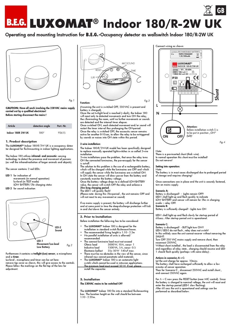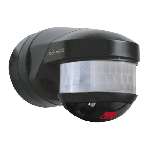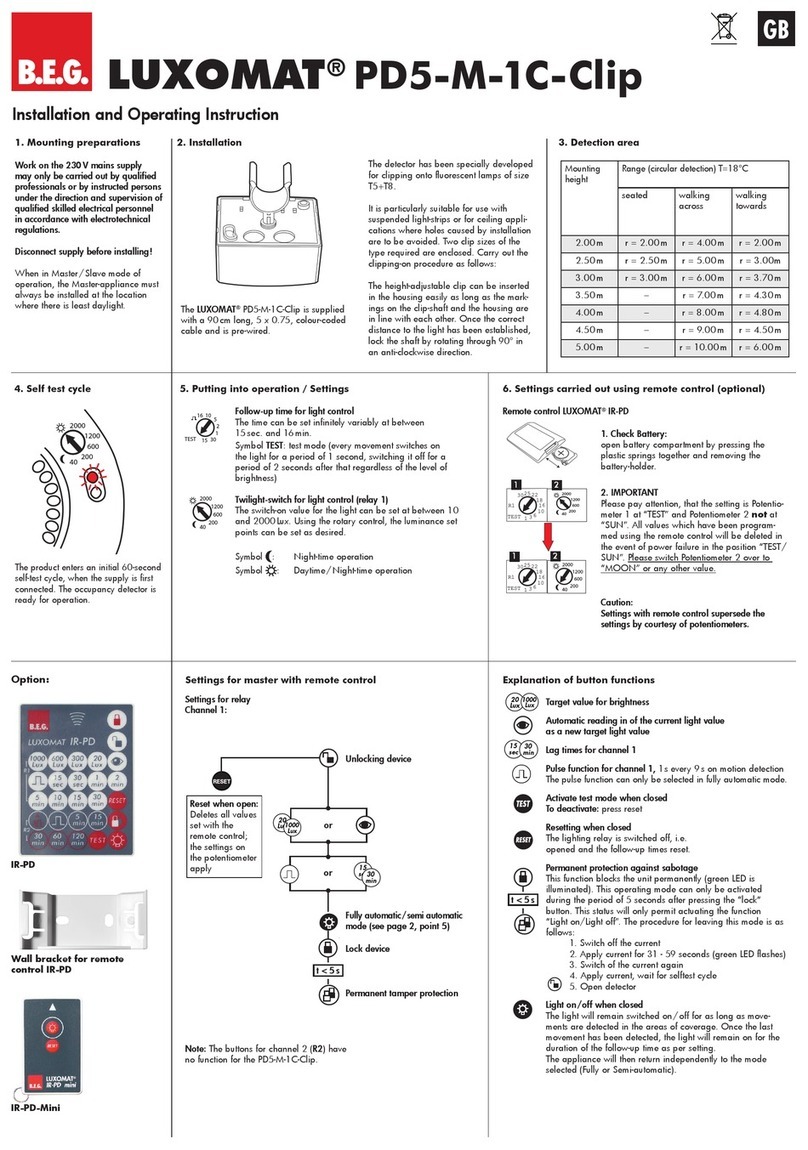
LUXOMAT®PD4-S-DAA4G
EN
Installation and Operating Instruction for B.E.G. PD4-S-DAA4G
1. Product information
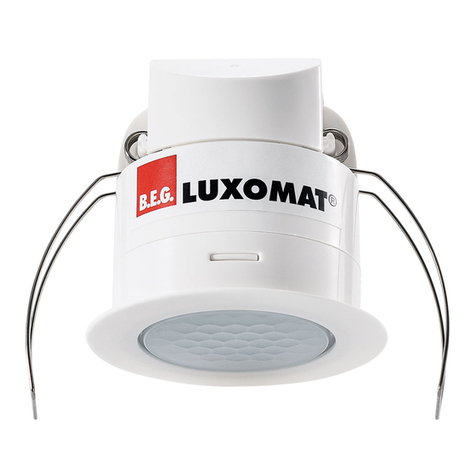
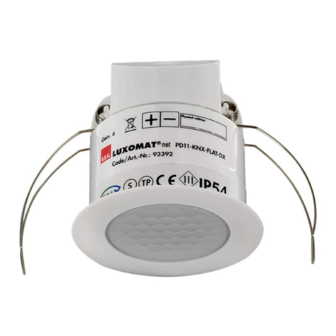
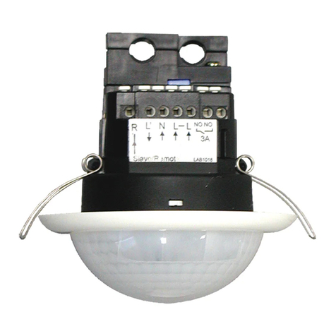
• Slave occupancy detector designed for PD4-M-DAA4G
compact DALI system
• For expansion of a master device’s detection area
• When movement is detected, a switch pulse is sent to the
master independent of ambient light level
• Simple mounting
• Automatic test mode via master device
• Plug & Play - no setup required
2. Operation
Work on electrical equipment should only be undertaken
by qualified electricians or by trained personnel under the
instruction and supervision of a trained electrician, according
to the regulations for electrical installation
Turn off the mains supply before fitting
This device is not to be used to isolate other equipment from
the mains supply
After inserting the connection cable, fit the supplied cover to
the detector
The push button inputs and the D+/D- terminals must not be
connected to the mains supply
3. Operation
3.1 General
The PD4-S-DAA4G is for expanding the detection area of a
PD4-M-DAA4G. Motion detection is based on passive infrared
technology. If people, animals or other heat sources move within
the detection area, the detector forwards motion detection events to
a PD4-M-DAA4G using a B.E.G. DALI protocol.
See Figure 3.1: Detection diagram
3.2. System characteristics
A maximum of four PD4-S-DAA4G can be controlled by one
PD4-M-DAA4G. Ideally, the detection areas should overlap by
about 30%. Power supply is via the DALI bus, with current consump-
tion of about 7 mA on average. The DALI bus must only be supplied
with the required voltage via the DALI power supply integrated into
the PD4-M-DAA4G.
See Figure 3.2: Circuit diagram
3.3 In use
The PD4-S-DAA4G sends a B.E.G. DALI telegram to the master
every 30 seconds, if motion is detected within this 30-second
period. If the master is in test mode, and the slave detects motion, it
sends a B.E.G. DALI telegram to the master every 2 seconds. After
3 minutes, the slave device automatically reverts to normal mode.
During the PD4-M-DAA4G addressing phase, no-one should
remain in the detection area of the PD4-S-DAA4G, as otherwise
there is a risk that not all DALI electronic ballasts will be detected
and addressed.
To be absolutely sure that no DALI telegram is sent from slave
to master during addressing of the DALI electronic ballasts, it is
recommended that the slaves are only connected to the DALI bus
after addressing of all DALI electronic ballasts.
4. Mounting
4.1. General
The ideal mounting location is inside, 2.5 to 3 metres high, on the
ceiling. Ventilation units should not be in the immediate vicinity of
the detector, as otherwise “false alarm” motion detection events
may be triggered.
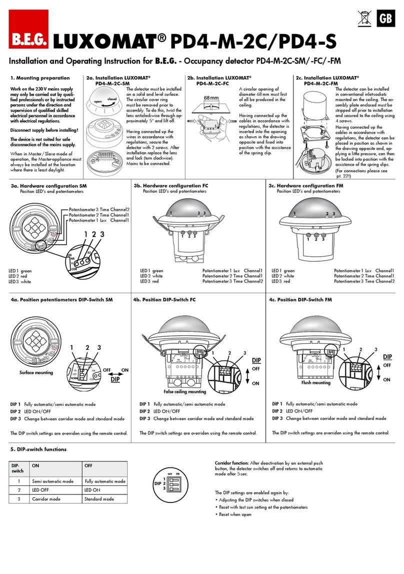
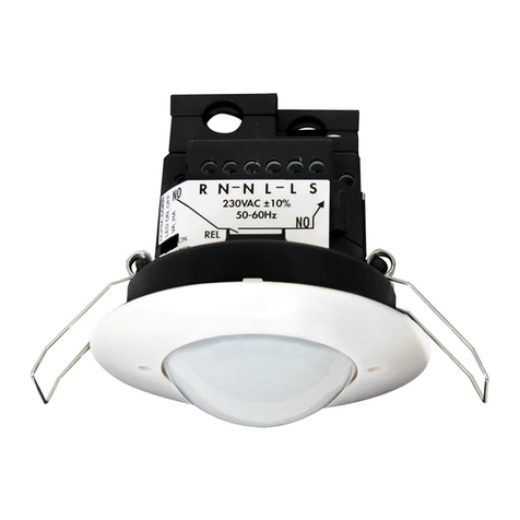
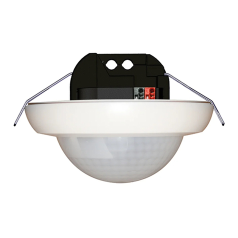
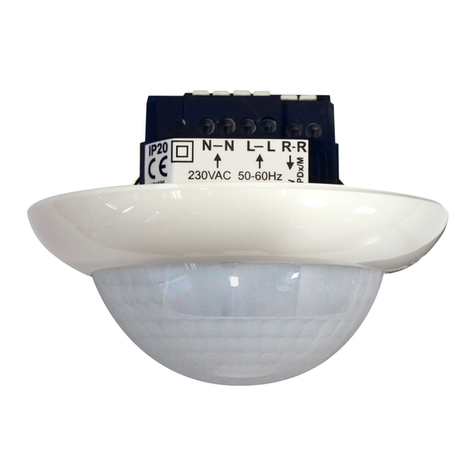
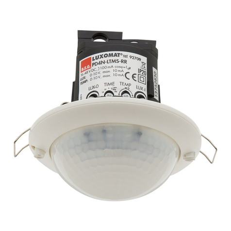
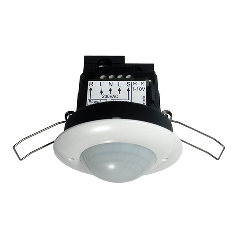
4.2. Connecting for false ceiling
A circular opening of diameter 68mm must first of all be produced
in the ceiling. Having connected up the cables in accordance with
regulations, the detector is inserted into the opening as shown in
the drawing opposite and fixed into position with the assistance of
the spring clip.
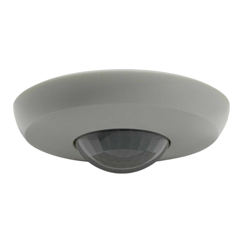
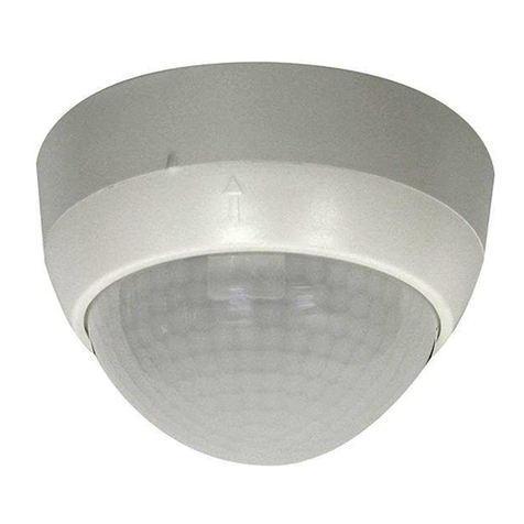
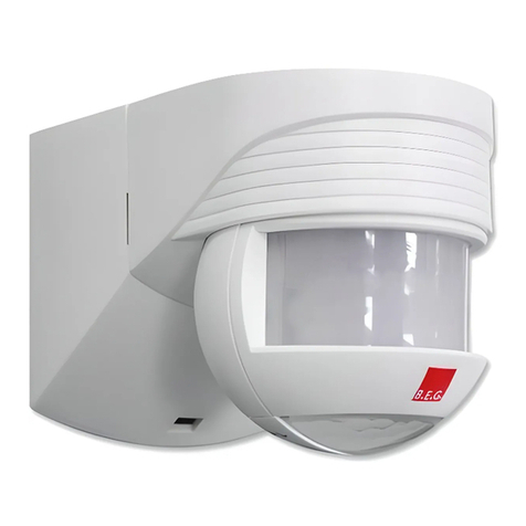
4.3 Connecting for surface
The detector must be fixed on a smooth, solid surface. Before moun-
ting, the lens must be removed. Turn the lens about 5° anticlockwise
and remove it. Undoing two screws allows the detector to be
removed from the socket. After properly connecting the wiring, and
attaching the socket to the ceiling with 2 screws, the detector must
be reattached to the socket with 2 screws. Then reattach the lens,
turning it clockwise.
See Figure 4.3: Surface mounting
4.4 Light sensor
The light sensor on the exterior of the cover ring is intended for
future applications.
See Figure 4.4: Light sensor LED
5. Self-test cycle
In the first 60 seconds from when the mains voltage is turned on,
the detector runs through a self-test cycle. During this period, the
device does not react to movement.
6. Initial operation
The PD4-S-DAA4G requires no setup or addressing, and is
therefore ready to use.
7. Blocking out sources of interference
In order to block out sources of interference, for example copiers
or air conditioning outlets, there is an option to fit clip-on covers
to the lens.
See FIGURE 7: Exclude sources of interference
8. LED Indication
Nr. Indication white
1Self-test cycle Blinking
2Movement detected Short ON
9.
Article / Part nr. / Accessory
Typ Part Info
PD4-S-DAA4G-FC 92721 Slave, version for false
ceiling mounting
PD4-S-DAA4G-SM 92759 Slave, version for surface
mounting
10.
Technical data
Power supply: max.22 V DC over DALI-Bus
Area of coverage: circular, 360°
Range of coverage: Ø 24 m transverse
Ø 8 m towards
Ø 6,4 m seated
Protection type/class: SM IP54, FC IP20 / II / CE
Ambient temperature: -25°C / +50°C
Dimensions FC : Ø 98 x 96mm
Dimensions SM : Ø 101 x 69 mm
Housing: Polycarbonate, UV-resistant
Puls interval: 30 seconds (2 seconds in the test mode
for a period of 3 minutes) Slave
DALI: Power supply via DALI bus of
PD4-M-DAA4G
Power consumption:
about 7 mA
maximum 4 slaves in combination with
a PD4-M-DAA4G
Declaration of conformity
This product respects the directives concerning
1. electromagnetic compatibility (2004/108/EU)
2. low voltage (2006/95/EU)
3. restriction of the use of certain hazardous substances in
electrical and electronic equipment (2011/65/EU)
11. Potential problems
There can be many causes of problems with lighting control. The
following shows a selection of possible causes.
Current draw of connected DALI units too high
In designing your system, please take into account the total current
draw of all DALI units (electronic ballasts and any slave devices).
The DALI power supply integrated into the PD4-M-DAA4G can
provide a stable supply voltage when total current draw of all DALI
units is 150 mA. Each DALI electronic ballast requires 2 mA. A
slave device requires 7 mA.
Too many slave devices connected
If more than 4 slave devices are connected to the PD4-M-DAA4G
DALI compact system, unexpected lighting control errors can occur.
Heat sources in vicinity
If, for example, the detector is in the immediate vicinity of
ventilation outlets or a projector, the warm air coming from these
can trigger motion detection. Position the detector sufficiently far
from potential sources of interference, such as ventilation outlets,
projectors, video units, copiers, printers etc.
MAN 8605 – PD4-S-DAA4G_EN–2– 250815
!
!
!
!
!
PD4-S-DAA4G_120515.indd 1 28.08.2015 11:18:15
