Page. 1
Table of Contents
Assembly and Use Instruction Manual......................................................................................................................1
Safety Instruction .....................................................................................................................................................2
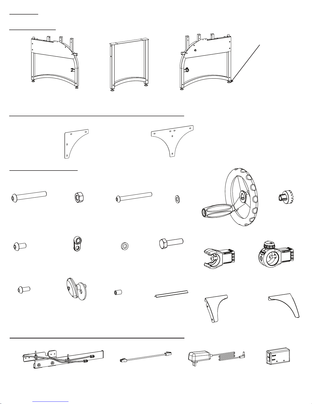
Parts List ...................................................................................................................................................................3
Corner Supports & Middle Leg Support Inner Box (Box 1).......................................................................................3
Hardware Box (Box 1)...............................................................................................................................................3
Corner Supports & Middle Leg Support Inner Box (Box 1).......................................................................................3
Hardware Box Continued (Box 1) .............................................................................................................................4
Box 2 Contents..........................................................................................................................................................4
Box 3 Contents..........................................................................................................................................................4
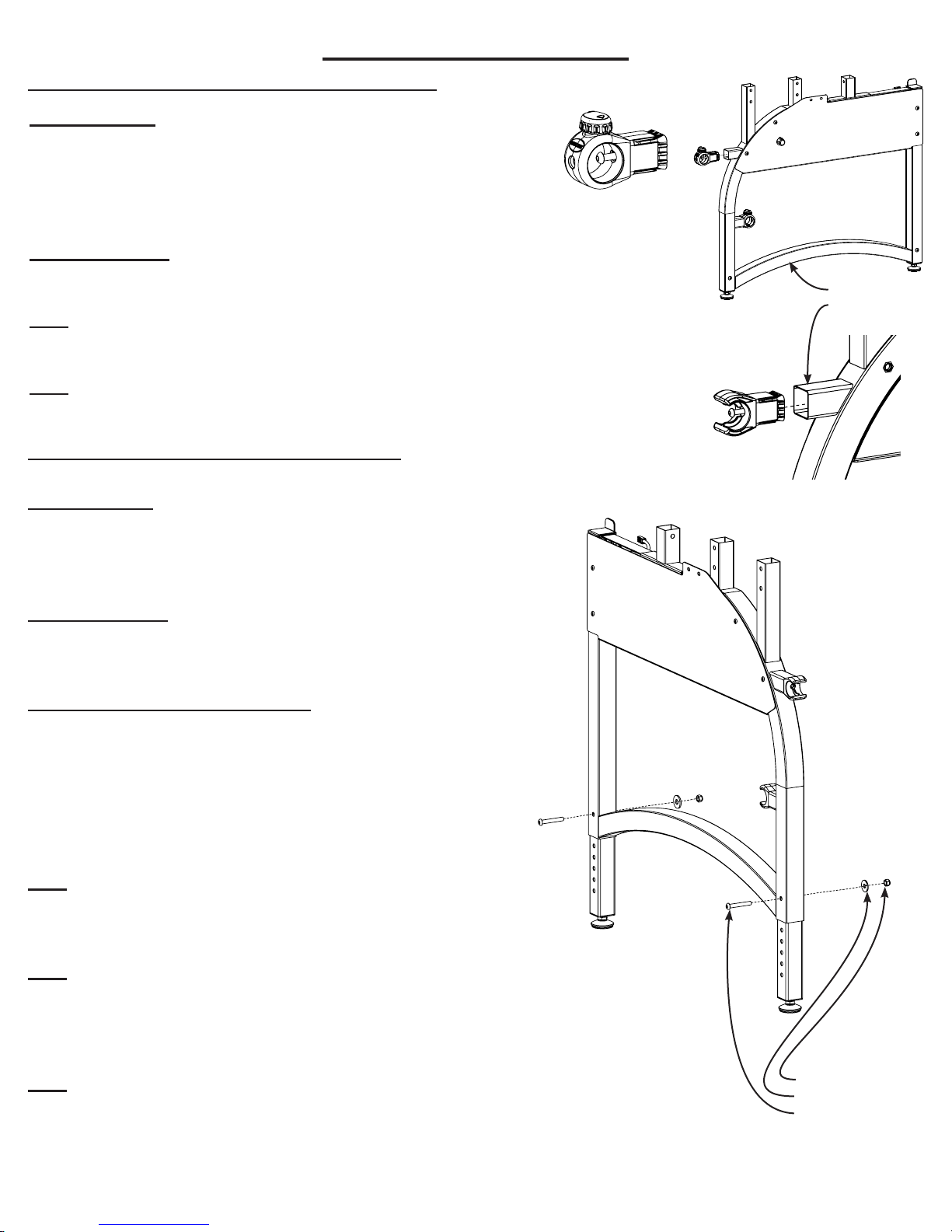
Step 1: Ratchet and Rail Holder Installation ............................................................................................................5
Step 2: Height Adjustable Leg Assembly ..................................................................................................................5
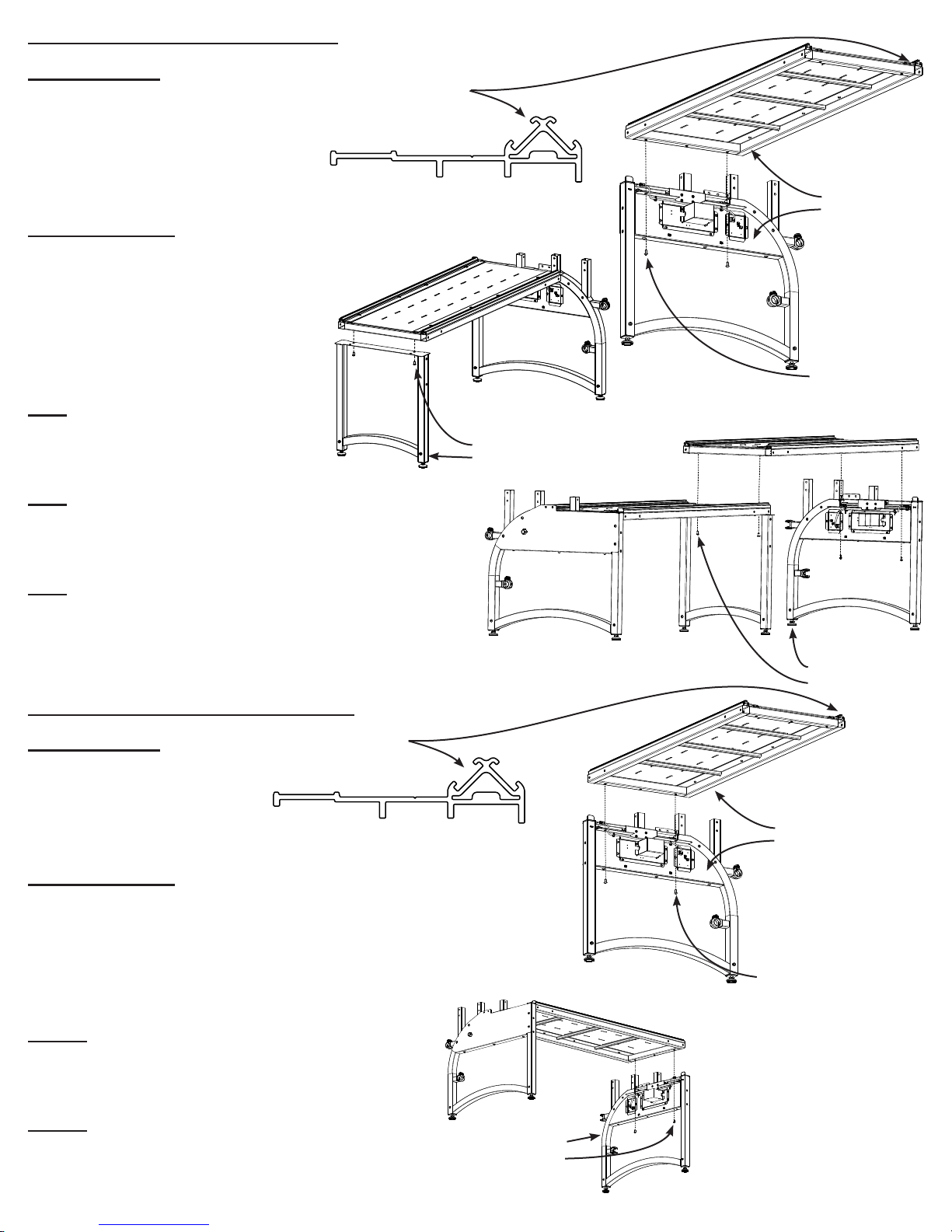
Step 3: King Table to Frame Ends .............................................................................................................................6
Step 3-C: Crib Table to Frame Ends...........................................................................................................................6
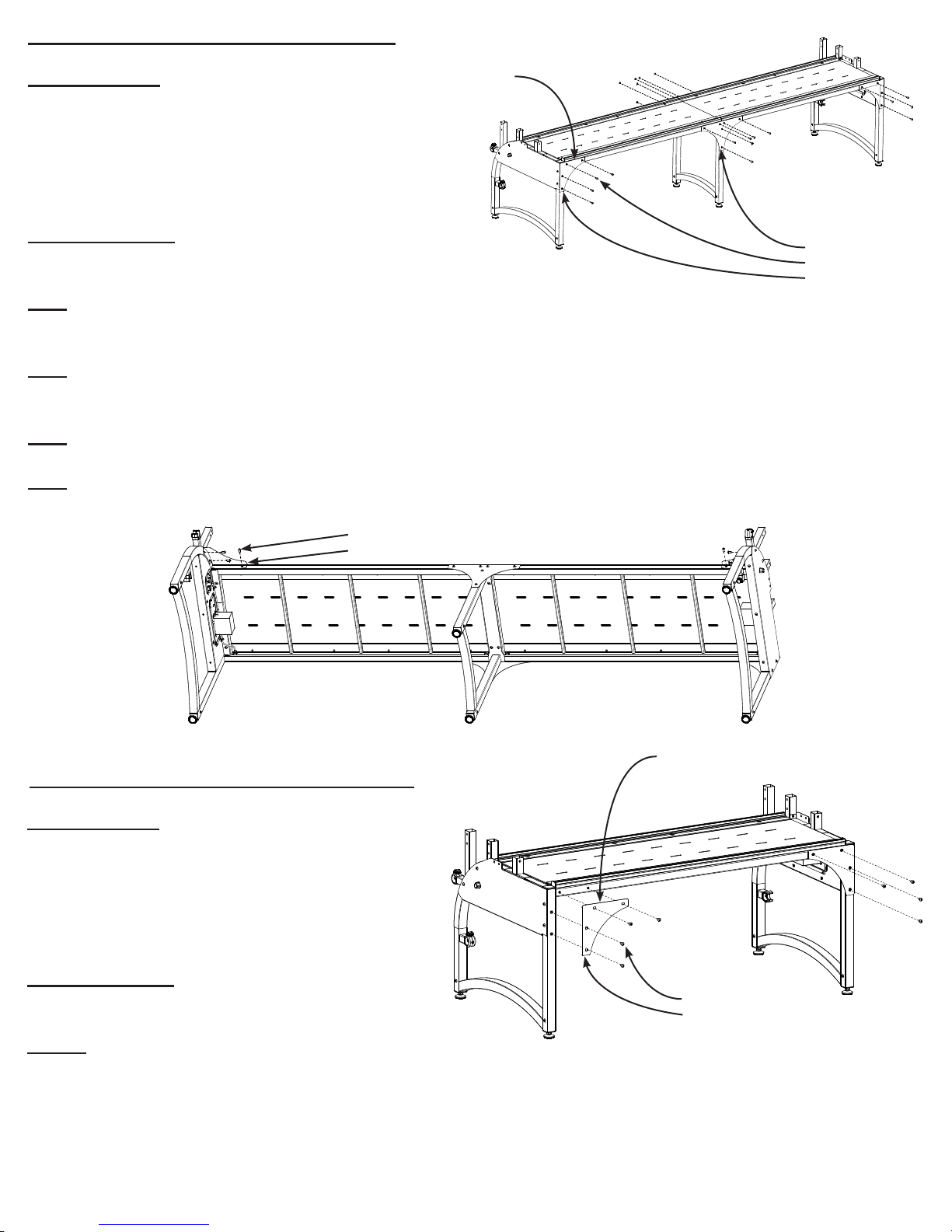
Step 4: Corner Brace for King Assembly ...................................................................................................................7
Step 4-C: Corner Brace for Crib Assembly.................................................................................................................7
Step 5: Track Assembly for King Size Frame.............................................................................................................8
Step 5-C: Track Assembly for Crib Size Frame..........................................................................................................9
Step 6: Front Rail Bracket Assembly.........................................................................................................................9
Step 7: Take Up Rail Bracket Assembly...................................................................................................................10
Step 8: Bottom Carriage Assembly..........................................................................................................................10
Step 9: Track Adjustment........................................................................................................................................11
Step 10: Rail Assembly for King..............................................................................................................................12
Step: 10-C: Rail Assembly for Crib..........................................................................................................................13
Step 11: Machine Magnetic Bracket........................................................................................................................13
Step 12: Idler Rail Clamp Attachment to Frame.....................................................................................................14
Step 13: Rail Attachment to Frame.........................................................................................................................15
Step 14: Handwheel Attachment to Rail End..........................................................................................................15
Step 15: Leveling Feet Adjustment.........................................................................................................................15
Step 16: Wire Connection........................................................................................................................................16
Step 17: Speed Control............................................................................................................................................17
Frame Center Diagram............................................................................................................................................17
Frame Rail Diagram.................................................................................................................................................18
Section 1: Fabri-Fast System...................................................................................................................................18
Section 2: Leader Cloth ...........................................................................................................................................19
Section 3: Attaching Fabric on the Frame Rails ......................................................................................................20
Section 4: Bungee Clamps.......................................................................................................................................22
Getting Started........................................................................................................................................................22
Trouble Shooting Guide...........................................................................................................................................23
Assembly and Use Instruction Manual
Version 2
Copyright January 1, 2016
Jim M. Bagley, GraceWood, Inc
(Reproduction Prohibited)
Version 2.1