manuals.online logo
Brands
  1. Home
  2. •
  3. Brands
  4. •
  5. Balluff
  6. •
  7. Industrial Equipment
  8. •
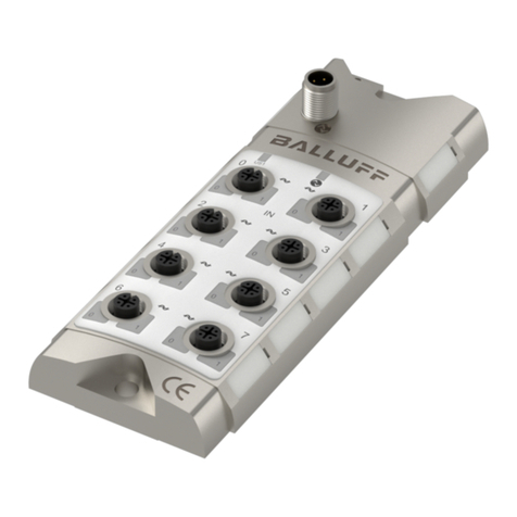
  9. Balluff BIC 1I22-P2A02-M18MN2-EPX07-050 User manual

Balluff BIC 1I22-P2A02-M18MN2-EPX07-050 User manual

Balluff Inductive Coupler
Montageanleitung / Installation Guide
www.balluff.com 1
BIC 1I22-P2A02-M18MN2-EPX07-050 (Base)
BIC 2I22-P2A02-M18MF2-EPX07-050 (Remote)
Diese Montageanleitung ersetzt nicht die Bedienungsanleitung. Für eine
ordnungsgemäße Installation und Betrieb lesen Sie bitte die
Bedienungsanleitung und die dazugehörigen Sicherheitshinweise
sorgfältig durch.
Diese finden Sie zum Download unter http://www.balluff.de.
Bitte wenden Sie sich bei weiteren Fragen an unseren Kundenservice.
These Installation Guide do not replace the User´s Guide. For proper in-
stallation and operation, please read the User´s Guide and associated
safety instructions carefully.
This is ready for you to download at http://www.balluff.com.
For any further question please contact our Customer Service.
Systemübersicht / System overview
Signal
Power
SPS
Sensor
Sensor
Sensor
Sensor
Base Remote
Der Sensor erfasst ein Objekt und überträgt das Signal an die Remote.
Diese leitet das Signal an die Base weiter, die es an die Steuerung wei-
tergibt. Die Base versorgt zugleich die Remote und die max. 4 Senso-
ren über Induktivkopplung mit der notwendigen Betriebsspannung. Die
Energie, die von der Remote an die Sensoren abgegeben wird, ist vom
Übertragungsabstand Y und vom Zentrumsabstand X zwischen Base
und Remote abhängig (siehe Kapitel Versatz / Offset).
Das BIC-
System verfügt über eine interne Temperaturüberwachung, die
das System vor Überhitzung schützt. Nach Auslösen der Temperatu-
rüberwachung erfolgt der automatische Wiederanlauf, sobald das BIC-
System abgekühlt ist.
Bei Kurzschluss oder Überstrom wird an der Base-Komponente die
Energieübertragung abgeschaltet. Der automatische Wiederanlauf star-
tet erst nach Beseitigung der Störungsursache.
Zur Visualisierung des Betriebszustandes des BIC-Systems ist in der
hinteren Kappe der Base- und der Remote-Komponente eine LED-An-
zeige integriert.
The Sensor detects the target object and transmits the signal to the Re-
mote. The Remote transmits the signal to the Base, which in turn trans-
mits it to the control unit. The Base inductively powers both the remote
and the sensors with the required operating voltage. The power on re-
mote and on the sensors depends on distance Y and Offset X between
Base and Remote (please see chapter Versatz / Offset).
The BIC system has an internal temperature monitoring that protects
the BIC system from overheating. After triggering the temperature moni-
toring of the automatic restart takes place as soon as the BIC system
has cooled. In short circuit or over-current power transmission is cut off
at the base component. The automatic restart starts only after the cause
has disappeared. For visualization of the operating state of the BIC-sys-
tem LED display is integrated in case of the base-and the remote com-
ponent.
Installation
Übertragungsabstand / Transmission distance
Voraussetzung für einen störungsfreien Betrieb des BIC-Systems ist die
Einhaltung des zulässigen Übertragungsabstandes.
Compliance with the permitted transmission distance is a prerequisite for
interference-free operation of the BIC system.
A (mm)
≤ 3
Gegenseitige Beeinflussung / Mutual interference
Um eine gegenseitige Beeinflussung von nebeneinander liegenden
Base und Remote zu vermeiden, müssen die angegebenen Mindest-
abstände eingehalten werden.
To prevent mutual interference with adjacent bases or remotes, the
specified minimum distances must be adhered to:
A (mm)
≥30
Zulässiger Winkel-Versatz / Permissible angular offset
A [mm]
Winkel/ Angle
1
15°
2
8°
3
0°
Einbau in Metall / Installation in metal
Beschädigung des Gerätes durch Induktionseffekte!
Metallische Objekte vor und zwischen den aktiven Flächen werden stark
erhitzt. Die Komponenten sind so einzubauen, dass sie keine metalli-
schen Objekte in der sich aus den Abständen A, B und C ergebenen
Zone befinden. Die Abstände A, B und C sind unabhängig voneinander
einzuhalten!
Damage to the unit by induction effects!
Metallic objects in front of and between the active surfaces are very hot.
The components are assembled so that they are no metal objects in
which devoted from the distances A, B and C zone. The distances A, B
and C are independently observed!
Typ
A (mm)
B (mm)
C (mm)
BIC 1I22-P2A02-M18MN2-EPX07-050
≥ 4
≥ 15
≥ 20
BIC 2I22-P2A02-M18MF2-EPX07-050
≥ 4
≥ 15
≥ 20
Versatz / Offset
X (mm)
Y (mm)
BIC 1I22-P2A02-M18MN2-EPX07-050
≤3
≤3
BIC 2I22-P2A02-M18MF2-EPX07-050
≤3 ≤3
Balluff Inductive Coupler
www.balluff.com 2
Technische Daten Base / Technical data Base
(5000)94
4
70 10
16,7
LED 24
LED
LED
Anzeige / Display
Funktion / Function
Grün/
Green
Statisch / Static
Verbindung aufgebaut /
Connection established
Langsam blinkend /
Slowly flashing
Power on, kein Remote ge-
funden /Power on, no re-
mote found
Schnell blinkend /
Quickly flashing
Überlast/ Kurzschluss /
Overload/short-circuit
Mechanische Daten / Mechanical data
Gehäusewerkstoff /
Housing material
Messing, Cu2n39Pb3 Imoly beschichtet /
Brass, Cu2n39Pb3 imoly plated
Werkstoff aktive Fläche /
Material active surface
PA66
Gehäuseschutzart /
Housing degree of
protection
IP 67
Abmessungen /
dimensions (d x l in mm)
M18 x 94
Gewindesteigung/
thread pitch
M18 x1 mm
Gewicht / Weight
350 g
Betriebstemperatur /
operating temperature
0°C…50°C
Lagertemperatur /
storage temperature
-10°C…70°C
Elektrische Daten / Electrical data
Betriebsspannung /
Supply voltage
24 V ± 10%
Stromaufnahme /
Current consumption
≤ 500mA
Leerlaufstrom /
Standby current
≤ 100 mA
Überlastschutz /
Overload protection
Ja / Yes
Kurzschlussschutz /
Short circuit protection
Ja / Yes
Verpolschutz /
Polarity protection
Ja / Yes
Anzahl digitale Ausgänge /
Number of digital outputs
4 x PNP
Max. Strombelastung der
Ausgänge / Max. current
load for outputs
50 mA
Betriebsbereitschaft /
Connection time
≤ 80ms
Übertragungsfrequenz /
Transfer frequency
60 Hz
Kabellänge / Cable length 5000 mm
Kabeldurchmesser D /
Cable diameter D
4,5 mm
Biegeradius / Bending ra-
dius
10 x D
Leitungsbelegung / line connection
Leitungstype PUR 7x0,34mm2 Farbe grau /
Cable type PUR 7x0,34mm
2
gray
color
Signal
WH
24V
BU
Funktionserde / Function ground
GY
DAV/in zone
BN
Sensor 1
PK
Sensor 2
YE
Sensor 3
GN
Sensor 4
Technische Daten Remote / Technical data Remote
(5000)61
4
37 10
24
M18x1
LED
LED
LED
Anzeige / Display
Funktion / Function
Grün/
Green
Statisch / Static
Verbindung aufgebaut /
Connection established
Schnell blinkend /
Quickly flashing
Überlast/ Kurzschluss /
Overload/short-circuit
Mechanische Daten / Mechanical data
Gehäusewerkstoff /
Housing material
Messing, Cu2n39Pb3 Imoly beschichtet /
Brass, Cu2n39Pb3 imoly plated
Werkstoff aktive Fläche /
Material active surface
PA66
Gehäuseschutzart /
Housing degree of
protection
IP 67
Abmessungen /
dimensions (d x l in mm)
M18 x 61
Gewindesteigung/
thread pitch
M18 x 1 mm
Gewicht / Weight
310 g
Betriebstemperatur /
operating temperature
0°C…50°C
Lagertemperatur /
storage temperature
-10°C…70°C
Elektrische Daten / Electrical data
Betriebsspannung /
Supply voltage
12 V ± 10%,
Anzahl digitale Eingänge /
Number of digital inputs
4 x PNP
Max. Ausgangsstrom /
Max. output current
100 mA
Zulässige induktive Last /
Permitted inductive load
≤ 200 mH
Zulässige kapazitive Last /
Permitted capacitive load
< 20 µF
Restwelligkeit /
Ripple
≤ 200mV
Überlastschutz /
Overload protection
Ja / Yes
Kurzschlussschutz /
Short circuit protection
Ja / Yes
Verpolschutz /
Polarity protection
Ja / Yes
Betriebsbereitschaft /
Connection time
≤ 80ms
Übertragungsfrequenz /
Transfer Frequency
60 Hz
Leitungslänge /
Cable length
5.000mm
Leitungsdurchmesser /
Cable diameter
4,5mm
Biegeradius /
Bending radius
10 x D
Leitungsbelegung / line connection
Leitungstype PUR 7x0,34mm2 Farbe grau /
Cable type PUR 7x0,34mm
2
gray
color
Signal
WH
24V
BU
Signal GND / signal ground
BN
Sensor 1
PK
Sensor 2
YE
Sensor 3
GN
Sensor 4
GY
NC (nicht belegt)
Bestellhinweise / Order information
Produkt / Product
Bestellcode / Order code
BIC 1I22-P2A02-M18MN2-EPX07-050
BIC007T
BIC 2I22-P2A02-M18MF2-EPX07-050
BIC007U
Nr. 937404 DE/EN
•
Edition L17
•
Replaces Edition K17
•
Subject to modification
Balluff Inductive Coupler
Hinweise / Sicherheitshinweise / Notes / Safety instructions
www.balluff.com 3
.
Die Installation und die Inbetriebnahme sind nur durch ge-
schultes Fachpersonal zulässig. Qualifiziertes Fachpersonal
sind Personen, die mit Arbeiten wie der Installation und dem
Betrieb des Produktes vertraut sind, und über die für diese Tä-
tigkeit notwendige Qualifikation verfügen. Bei Schäden, die
aus unbefugten Eingriffen oder nicht bestimmungsgemäßer
Verwendung entstehen, erlischt der Garantie- und Haftungs-
anspruch gegenüber dem Hersteller. Der Betreiber hat die
Verantwortung, dass die im spezifischen Einzelfall geltenden
Sicherheits- und Unfallverhütungsvorschriften eingehalten
werden.
Installation and startup are to be performed only by trained
specialists. Qualified personnel are persons who are
familiar with the installation and operation of the product, and
who fulfills the qualifications required for this activity. Any
damage resulting from unauthorized manipulation or improper
use voids the manufacturer's guarantee and
warranty. The Operator is responsible for ensuring that
applicable of safety and accident prevention regulations are
complied with.
Gefährliche Spannung
Vor dem Arbeiten an dem Gerät dessen Stromversorgung ab-
schalten.
Hazardous voltage
Disconnect all power before servicing equipment.
Bestimmungsgemäßer Gebrauch
Induktive Koppelsysteme (BIC) sind Geräte zur berührungs-lo-
sen Energie- und Signalübertragung in industriellen Umgebun-
gen.
Unzulässig ist insbesondere die Verwendung:
•in Umgebung mit explosiver Atmosphäre,
•in Anwendung bei denen die Sicherheit von
Personen oder Maschinen von übertragenen Sig-
nalen abhängt. (Sicherheitsrelevante Schal-
tungen).
Intended use
Inductive coupling systems (BIC) are devices for contactless
energy and signal transmission in industrial environments.
Prohibited is the use:
•in environment with explosive atmosphere.
•In application where the safety of persons or
machines depends on the transmitted signals.
(Safety circuits).
Vorsicht!
Verbrennungsgefahr durch heiße Oberflächen! Das BIC-
System erwärmt sich schon unter normalen Einsatz-
bedingungen. Hände und Gegenstände von der aktiven Flä-
che fern halten. Metallische Gegenstände dürfen nicht in
Zone A, B und zwischen die aktiven Flächen von Base und
Remote gelangen. Brandgefahr!
Caution!
Risk of burning on hot surfaces! The BIC system heats
up under normal operating conditions. Keep hands and
objects away from the active surface. Metallic objects should
not reach the area between the sensing surfaces of the
Base and Remote units. Fire hazard!
Schutz vor elektromagnetischen Feldern bei Betrieb und
Montage
Die zulässigen Werte nach VDE 0848 Teil 3-1 werden ab ei-
nem Abstand von ≥10 mm eingehalten. Für Personen mit Kör-
perhilfen (z.B. Herzschrittmacher), können durch die vom BIC-
System ausgehenden magnetischen Felder, Gesundheitsge-
fährdungen ausgehen. Der Mindestabstand für diesen Perso-
nenkreis beträgt ≥15 mm. Der Betreiber hat dafür Sorge zu tra-
gen, dass dieser Mindestabstand auch während des Betriebes
durch geeignete Maßnahmen eingehalten wird.
Protection from electromagnetic fields during operation
and assembly
The permitted values in accordance with VDE 0848 part 3-1
are maintained starting at a distance of ≥10 mm. The magnetic
fields emitted by the BIC system may pose a health hazard to
persons with medical aids such as a pacemaker. The minimum
distance for this group of persons is ≥15 mm. The operator is
responsible for this minimum distance also being maintained
through suitable measures during operation.
Hinweis
Diese Montageanleitung ersetzt nicht die Bedienungsan-
leitung. Lesen Sie die Bedienungsanleitung vor der Inbetrie-
nahme des BIC-Systems durch. Die Bedienungsanleitung fin-
den Sie auf der Balluff-Homepage.
Note
These installation instructions do not replace the manual.
Read through the instruction before operating the BIC system.
The manual is available on the Balluff website.
Hinweis
Im Interesse einer ständigen Verbesserung des Produkts be-
hält sich die Balluff GmbH vor, die technischen Daten des
Produkts und den Inhalt dieser Anleitung jederzeit, ohne An-
kündigung zu ändern.
Note
In the interest of product improvement, the Balluff GmbH re-
serves the right to change the specifications of the product
and the contents of this manual at any time without notice.
Other manuals for BIC 1I22-P2A02-M18MN2-EPX07-050

1

This manual suits for next models

3

Other Balluff Industrial Equipment manuals

Balluff BMP 01-EL1PP 1A Series User manual

Balluff

Balluff BMP 01-EL1PP 1A Series User manual

Balluff BTL7-A510-M-SF-F Series User manual

Balluff

Balluff BTL7-A510-M-SF-F Series User manual

Balluff BIC 1I3-P2A50-M30MI3-SM4ACA User manual

Balluff

Balluff BIC 1I3-P2A50-M30MI3-SM4ACA User manual

Balluff BTL5-S1-M/U-K-SR32/K Series Parts list manual

Balluff

Balluff BTL5-S1-M/U-K-SR32/K Series Parts list manual

Balluff BTL5-A11-M Series User manual

Balluff

Balluff BTL5-A11-M Series User manual

Balluff BOS R254K-UUI-RH11-S4 User manual

Balluff

Balluff BOS R254K-UUI-RH11-S4 User manual

Balluff BTL6-P510-M-E2/E28-KA/LA Series User manual

Balluff

Balluff BTL6-P510-M-E2/E28-KA/LA Series User manual

Balluff BTL7-S5 B-M Series User manual

Balluff

Balluff BTL7-S5 B-M Series User manual

Balluff Micropulse BTL5 Series User manual

Balluff

Balluff Micropulse BTL5 Series User manual

Balluff Micropulse BTL7-S510B Series User manual

Balluff

Balluff Micropulse BTL7-S510B Series User manual

Balluff BTL PA0400 Series User manual

Balluff

Balluff BTL PA0400 Series User manual

Balluff BNI IOL-104-011-K006 User manual

Balluff

Balluff BNI IOL-104-011-K006 User manual

Balluff BTL PF 400 Series User manual

Balluff

Balluff BTL PF 400 Series User manual

Balluff BTL5-S1 Series User manual

Balluff

Balluff BTL5-S1 Series User manual

Balluff SMARTCAMERA User manual

Balluff

Balluff SMARTCAMERA User manual

Balluff BTL PA0400 Series User manual

Balluff

Balluff BTL PA0400 Series User manual

Balluff BTL5-P/I/L/M1-M-H/W(8)-S32/KA/K Series User manual

Balluff

Balluff BTL5-P/I/L/M1-M-H/W(8)-S32/KA/K Series User manual

Balluff BTL PF 400 Series User manual

Balluff

Balluff BTL PF 400 Series User manual

Balluff BTL6-A500/B50 M Series User manual

Balluff

Balluff BTL6-A500/B50 M Series User manual

Balluff Ethernet/IP BTL7-V50D Series Instruction sheet

Balluff

Balluff Ethernet/IP BTL7-V50D Series Instruction sheet

Balluff BTL7-E508-M P-S32/KA Series User manual

Balluff

Balluff BTL7-E508-M P-S32/KA Series User manual

Balluff BIS U-4A7-082-01C-07-S4 User manual

Balluff

Balluff BIS U-4A7-082-01C-07-S4 User manual

Balluff BOS R090K-U-RX10-S49 Series User manual

Balluff

Balluff BOS R090K-U-RX10-S49 Series User manual

Balluff BTL5-A/C/E1-MSF-F Series User manual

Balluff

Balluff BTL5-A/C/E1-MSF-F Series User manual

Popular Industrial Equipment manuals by other brands

VALLEY CRAFT ROTOLIFT-78 AIR instruction manual

VALLEY CRAFT

VALLEY CRAFT ROTOLIFT-78 AIR instruction manual

Watercool HEATKILLER TUBE Series Assembly instructions

Watercool

Watercool HEATKILLER TUBE Series Assembly instructions

EVAPCO PMC Series Rigging & Assembly Instructions

EVAPCO

EVAPCO PMC Series Rigging & Assembly Instructions

Rothenberger RODIACUT 150 Instructions for use

Rothenberger

Rothenberger RODIACUT 150 Instructions for use

ABB HT566551 Operation manual

ABB

ABB HT566551 Operation manual

Lippert JT's Strong Arm Travel Trailer Installation and owner's manual

Lippert

Lippert JT's Strong Arm Travel Trailer Installation and owner's manual

Greenheck ESD-635D installation instructions

Greenheck

Greenheck ESD-635D installation instructions

Haas Automation UMC installation instructions

Haas Automation

Haas Automation UMC installation instructions

ixtur MRP-100NK Technical Specifications and Instructions

ixtur

ixtur MRP-100NK Technical Specifications and Instructions

fiorini SET PLUS 2.0 - 25 Use and maintenance manual

fiorini

fiorini SET PLUS 2.0 - 25 Use and maintenance manual

AERMEC SAP 0075 Booklet

AERMEC

AERMEC SAP 0075 Booklet

SMC Networks INR-244-757 Operation manual

SMC Networks

SMC Networks INR-244-757 Operation manual

Eastwood 10049Z operating instructions

Eastwood

Eastwood 10049Z operating instructions

Blastrac BDC-66 operating instructions

Blastrac

Blastrac BDC-66 operating instructions

IMET VTF 500 INSTRUCTION MANUAL, MAINTENANCE AND SPARE PARTS

IMET

IMET VTF 500 INSTRUCTION MANUAL, MAINTENANCE AND SPARE PARTS

CAB 4126C Assembly instruction

CAB

CAB 4126C Assembly instruction

ROBAND CHOC1 operating instructions

ROBAND

ROBAND CHOC1 operating instructions

Jensen EXTREME 870272 manual

Jensen

Jensen EXTREME 870272 manual

manuals.online logo
manuals.online logoBrands
  • About & Mission
  • Contact us
  • Privacy Policy
  • Terms and Conditions

Copyright 2025 Manuals.Online. All Rights Reserved.