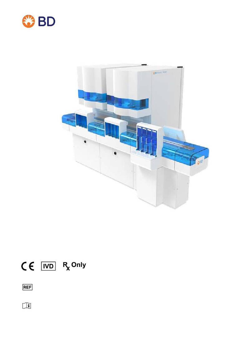
BD Kiestra Track User manual

Kiestra™ Track
User's Manual
BD Kiestra B.V.
Marconilaan 6
9207 JC Drachten, The Netherlands
Australian and New Zealand Sponsors:
Becton Dickinson Pty Ltd.
66 Waterloo Road
Macquarie Park NSW 2113, Australia
Becton Dickinson Limited
14B George Bourke Drive
Mt. Wellington Auckland 1060, New Zealand
L011042(03) 2021-10
446097, 446942
English
bd.com/e-labeling

BD Kiestra™ Track User's Manual
Change History
Revision Date Change Summary
01 2019-10 Initial release
02 2020-01
Minor typographical corrections. Updated
Australian and New Zealand Sponsors Addresses,
and Utility and Module Operating Requirements.
Added information about black agar plate usage in
sections 2.3.2 and 4.4, information about the cover
latch in the section 4.7, and added "or closing" to
pinch hazard warnings about opening or closing a
cover.
03 2021-09
Minor typographical and formatting corrections.
Added Customer Release Notes topic. Added an
Ordering information topic. Updated BDKiestra™
Track elements to include BarcodA and InoqulA.
Added the Regular Base cabinet and updated the
Main Base cabinet in the Elements overview topic.
Updated the BDKiestra™ Track GUI topic,
BDKiestra™ ReadA remote view topic, and the
Collecting plates from a Stacker topic. Updated the
screenshots and text in the Status view,
Notifications, Starting operation, Resolving errors
topics. Updated screenshots in the General layout,
Help, User account, and Configuration topics.
Updated and renamed the Error, warning, and
information messages topic. Updated Module
specifications to include the Main Base, Main Base
Light, and Regular Base specifications.
BD, the BD Logo, Kiestra, and Synapsys are trademarks of Becton, Dickinson and Company
or its affiliates. All other trademarks are the property of their respective owners. ©2021BD. All
rights reserved.
No part of this publication may be reproduced, transmitted, transcribed, stored in retrieval
systems, or translated into any language or computer language, in any form or by any means,
electronic, mechanical, magnetic, optical, chemical, manual, or otherwise, without the prior
written permission of BD Kiestra, B.V., Marconilaan 6, 9207 JC Drachten, The Netherlands.
2

3
Table of Contents
1 Instructions for use guidance 5
1.1 Customer release notes 5
1.2 Conventions 5
1.3 Notes, cautions, and warnings 5
1.4 Symbols glossary 6
1.5 Depiction of patient information 7
2 Introduction 9
2.1 Intended use 9
2.2 Module startup 9
2.3 Module description 9
2.3.1 BDKiestra™Track elements 9
2.3.1.1 Elements overview 11
2.3.1.2 Stacker element 13
2.3.1.3 Destacker element 14
2.3.1.4 Standard Connector element 15
2.3.1.5 Straight element 16
2.3.1.6 U-turn element 16
2.3.2 Plate flow 16
2.3.3 BDKiestra™ Track GUI 18
2.3.3.1 General layout 18
2.3.3.2 Status view 19
2.3.3.3 BDKiestra™ReadA remote view 24
2.3.3.4 Utilities view 25
2.3.3.5 Notifications 26
2.3.3.6 Help 27
2.3.3.7 User account 28
3 Configuration 29
3.1 Language settings 30
4 Operation 31
4.1 Turning on module 32
4.2 Starting operation 34
4.3 Signing in and out 35
4.4 Placing plates in a Destacker 36
4.5 Collecting plates from a Stacker 37
4.6 Pausing operation 38
4.7 Opening covers 39
4.8 Turning off module 41
5 Cleaning and maintenance 43
5.1 Cleaning and disinfection 44
5.1.1 Frequency of routine cleaning 44
5.1.2 Cleaners and disinfectants 44
5.2 Cleaning methods 45
5.2.1 Dry cleaning 45
5.2.2 Wet cleaning/disinfecting 45

4
5.3 General cleaning procedure 46
5.4 Cleaning components 48
5.4.1 Touchscreen 48
5.4.2 Sensors 48
5.4.3 Scanner windows 48
5.4.4 Conveyor belts 48
5.4.5 Stackers and Destackers 49
5.4.6 Blue covers 49
5.4.7 Internal and external surfaces 49
5.5 Incidental cleaning 49
5.6 Decontamination 50
6 Troubleshooting 53
6.1 Resolving errors 53
6.2 Error, warning, and information messages 56
7 Contacts 63
8 Limited warranty 65
9 Installation requirements 67
9.1 Module specifications 67
10 Ordering information 71
11 Glossary 73
12 Index 77
BD Kiestra™ Track User's Manual

5
1 Instructions for use guidance
Before using the product, it is recommended that all users become thoroughly familiar with the
contents of the instructions for use.
These instructions for use are a reference tool for trained laboratory personnel who operate
and maintain the product on a regular basis. Every attempt has been made to include all
information which would be required during normal use and maintenance.
EU Only: Users should report any serious incident related to the device to the Manufacturer
and National Competent Authority.
OutsideEU: Contact your local BD representative for any incident or inquiry related to this
device.
Technical Service and Support: In the United States contact BD at 1.800.638.8663 or bd.com.
For regions outside of the United States, contact your local BD representative or bd.com.
Should a question arise that is not answered in these instructions, please contact BD.
See7Contacts.
1.1 Customer release notes
Customer release notes (in English) are available at bd.com/e-labeling.
1.2 Conventions
The following conventions are used in this guide:
Convention Example
Bold type is used for software options and to
indicate a menu path.
Select Save and select OK.
Select File > Save As.
Italics type is used for names of documents. For more information, refer to the Example
Instrument User's Manual.
1.3 Notes, cautions, and warnings
Throughout the instructions for use, important information is presented in boxes offset from the
regular text that are labeled as a NOTE, CAUTION, or WARNING. These messages are
formatted as follows:
NOTE
Information worthy of special attention is presented as a NOTE.

6
CAUTION
Information on an activity which potentially could cause a product to malfunction
is presented as a CAUTION.
WARNING
INFORMATION ON AN ACTIVITY WHICH POTENTIALLY COULD CAUSE INJURY
TO THE USER IS PRESENTED AS A WARNING.
1.4 Symbols glossary
Some symbols listed below may not apply to this product.
US Customers only: For symbols glossary, refer to bd.com/symbols-glossary.
Symbol Meaning
CE marking; Signifies European
technical conformity
In vitro diagnostic medical device
This only applies to US: “Caution:
Federal Law restricts this device to sale
by or on the order of a licensed
practitioner.”
Manufacturer
Authorized representative in the
European Community
Authorised representative in Switzerland
Catalogue Number
Consult instructions for use or consult
electronic instructions for use.
Biohazard
Collect separately.
Indicates separate collection for waste of
electrical and electronic equipment
required.
Cut or sever hazard
BD Kiestra™ Track User's Manual

Symbol Meaning
Danger of crushing
Do not step
Earth terminal to ground
Electrical shock
Frame/chassis
Hot surface
Class 2 laser
Low clearance
Moving parts - pinch point
Pinch point
Refer to accompanying documentation
Sharp point
UV lamp
Indicates internal high voltage cables
that remain powered after the power
switch is turned off
1.5 Depiction of patient information
Patient names, identification numbers, and medical information presented in the instructions
for use, including those within images of the graphical user interface (GUI), are provided as
examples only, and do not represent actual patients or clinical information.
7
1 - Instructions for use guidance

8
BD Kiestra™ Track User's Manual

9
2 Introduction
2.1 Intended use
The BDKiestra™ Track provides transportation of plated media between various modules
within BDKiestra™ Laboratory Automation Solutions and is intended to be used in clinical
laboratories.
WARNING
WEAR PERSONAL PROTECTIVE EQUIPMENT (LAB COAT, GLOVES, SAFETY
GLASSES) WHEN INTERACTING WITH THE MODULE.
2.2 Module startup
When power is applied to the module, the following operations are performed:
lHardware is checked and initialized.
lVarious sensors and subsystems are verified.
The module reports any problems that require user attention through alerts. If any problem
arises that would prevent proper operation, the startup process is aborted. If the startup
procedures are successful, the module is ready to be used.
BD recommends that the module remain powered on at all times except during certain
maintenance procedures.
2.3 Module description
This section describes the Track elements, general flow of plates, and the GUI.
2.3.1 BDKiestra™Track elements
Track is a configuration of elements designed to adapt to various laboratory workflows, within
basic rules and constraints.
Track elements are designed to:
lreceive and collect plates
ltransport plates
linterconnect modules
Track can be physically connected to the following modules:
lBDKiestra™ BarcodA
lBDKiestra™InoqulA
lBDKiestra™ReadA

10
Figure 1 — Example Track configuration with ReadA
Figure 2 — Example Track configuration with InoqulA and BarcodA
BD Kiestra™ Track User's Manual

2.3.1.1 Elements overview
Base cabinets
Track elements typically sit upon a base cabinet, although some elements are able to float.
Main Base cabinet
AllTrack modules have one designated
Main Base cabinet, which houses the
computer and monitor where the GUI is
displayed.
A Main Base Light cabinet may be used
depending on the power needs of some
configurations.
Regular Base cabinet
A Regular Base cabinet houses the
electrical components needed to power
Track and is used to extend the power
capacity when needed.
Indicators and audible alarms
Each Track element contains an LED light bar which illuminates the element during normal
operations. This LED light bar, along with an audible alarm in the Main Base cabinet, is used to
inform the user when a warning or error situation has occurred.
The following colors are used in the light bar:
Color Meaning
No color Track is not operational, or the white light is turned off.
White
Track is active, no user intervention is needed.
Note: the white light can be turned off by BDTechnical Services.
Red
An error has occurred on that particular Track element.
In case of a generalTrack error, the Track element on top of the Main Base
cabinet, which houses the GUI monitor, is illuminated in red.
See 6Troubleshooting for more information on resolving errors.
Orange
A warning has occurred on that particular Track element.
See 2.3.3.5Notifications for more information on resolving warnings.
11
2 - Introduction

12
Transport lanes
All Track elements contain belts to move plates. These belts, which make up transport lanes,
carry plates across each Track element and to other elements and modules.
There are two types of transport lanes: a main lane and a side lane.
Main lane
The main lane (1) is a closed loop. Motion
continues while plates are on the main lane.
Side lanes
Side lanes (2) allow a plate to enter or exit the
main lane in order to transfer on and off the
Track element. A side lane is not a closed
loop. Motion on the side lanes will only stop if
the main lane is stopped.
Components
Track elements include components that interact with the plates, mechanically or physically.
Icon Illustration Component
N/A
Sensors
Sensors (1) detect the presence of a plate.
Stoppers
Stoppers temporarily stop a plate from traveling.
There are two types of Stoppers:
lSide Stoppers (2) block plates by jutting out
from the side of a lane.
lTapered Stoppers (3) block plates by jutting
out from the bottom of a lane.
Catchers
Catchers (4) capture a plate and transfer the plate
to another transport lane. The two icons depict
the transport line either :
lmerging from a side lane to the main lane, or
lsplitting off from the main lane to a side lane.
BD Kiestra™ Track User's Manual

Icon Illustration Component
Scanners
Scanners (5) read the barcode on a plate.
N/A
Plate carts
Plate carts (6) store plates received from the
Stacker element, and can hold up to 600 plates.
2.3.1.2 Stacker element
The Stacker element is the endpoint destination for plates on Track, designed to collect plates
to be retrieved by the user.
Image Schematics
Note: The actual representation of the Track element may vary based on the configuration of the Track.
The Stacker element has a main lane and a side lane, and includes one Catcher to facilitate
the transition from the main lane to the side lane. The side lane supports four Stackers, each of
which can stack up to 15 plates. When a stack has reached its desired height, the stack is
pushed onto a plate cart positioned in front of the Stacker element.
NOTE
The plate cart is divided into four compartments, each corresponding to an individual
Stacker. The compartments are adjustable and can vary in size.
The height of the plate cart should be adjusted to align the cart with individual Stacker
elements. Plate carts are not interchangeable between Stacker elements because of the
necessary height customization.
Two Stackers are defined by default to support basic functionality of the module:
lerror plates Stacker
lundeliverable plates Stacker
13
2 - Introduction

14
Remaining Stackers may be defined for other various reasons, such as:
lplates intended for discard
lplates intended for external incubation
lplates that need follow-up work
lplates marked for manual review
lplates marked as waste (positive or negative)
Configuration of the Stackers is done by BDTechnical Services, taking into consideration the
needs of each individual lab.
NOTE
During startup ofTrack, plates that are on the side lane of the Stacker element, but not yet
stacked, are moved back onto the main lane.
See 4.5Collecting plates from a Stacker for details on interacting with the Stackers.
2.3.1.3 Destacker element
The Destacker element is the point of entry for the user to add plates toTrack. It is designed to
store plates and automatically transport them, one at a time, to the main transport lane.
Image Schematics
Note: The actual representation of the Track element may vary based on the configuration of the Track.
The Destacker element has a main lane and a side lane. A Catcher is used to facilitate the
transition of plates from the side lane to the main lane. A Destacker will release and place a
plate on the side lane once the Destacker door is closed and the side lane is empty.
The Destacker element contains four Destackers, each of which can store up to 30 plates. The
left most Destacker has the default priority and allows for quick processing of priority
specimens. After destacking, the plate travels to the side lane. When the main lane is ready to
receive a plate, the Catcher moves the plate onto the main lane.
BD Kiestra™ Track User's Manual

NOTE
A Destacker can continue to process a plate if the door is opened while it is active.
Opening the door will not directly stop the procedure.
See 4.4Placing plates in a Destacker for details on interacting with a Destacker.
2.3.1.4 Standard Connector element
The Standard Connector element transports plates to connected BDKiestra modules. The
Standard Connector element has one main lane and two side lanes that connect to the
module: one side lane sends plates to the module, one receives plates from the module.
Image Schematics
Note: The actual representation of the Track element may vary based on the configuration of the Track.
The Standard Connector element includes two Catchers to facilitate the transition from the
main lane to the side lane and vice versa. If an arriving plate must be routed to the connected
module, the plate is guided to the side lane and is positioned in front of the connected module.
After successful negotiation between Track and the module, the plate is transferred into the
connected module.
Plates leaving the connected module are routed to the side lane of the Track element. The
Catcher moves the plate onto the main lane when the main lane is ready to receive the plate.
15
2 - Introduction

16
2.3.1.5 Straight element
The Straight element transports plates over the distance of the element with only one main
transport lane. It does not have the option of plates exiting or entering via side lanes. A Straight
element is mainly used to complement another Track element like a Standard Connector,
Stacker, or Destacker element.
Image Schematics
Note: The actual representation of the Track element may vary based on the configuration of the Track.
2.3.1.6 U-turn element
The U-turn element turns the plate transport direction 180 degrees and scans the plates to
identify them. The U-turn element has one main lane and is only used at the end of a transport
lane, completing the main transport loop. It does not have the option of plates exiting or
entering via side lanes.
Image Schematics
Note: The actual representation of the Track element may vary based on the configuration of the Track.
2.3.2 Plate flow
A plate that enters the Track does so either by the use of a Destacker or through a connected
module.
The basic flow of a plate from a start location to a destination location is described below:
1. A Destacker or connected module releases a plate onto the side lane of the Destacker
element or the Standard Connector element; this is the start location of the plate. At this
point, when the plate enters the Track, its destination is unknown to Track.
BD Kiestra™ Track User's Manual

2. From the side lane, the plate is guided onto the main lane by the Catcher, and merges
with the rest of the plate traffic. The transport lane will move the plate from element to
element, using sensors to keep track of and space the plate appropriately.
NOTE
In specific environmental conditions, a black agar plate may form
condensation on the bottom, which may render the plate undetectable by
a sensor. In that case, an error will be triggered and Track will need to be
restarted.
3. Once the plate reaches the U-turn element, the Scanner will read the barcode of the plate
and communicate with the control software to determine the plate's destination, for
instance a Stacker element or connected module.
NOTE
If the barcode cannot be read after an established number of tries, the
plate is marked as an error plate and is directed to the error plates
Stacker.
4. The plate is then transported toward the destination using the main lane. When the plate
reaches the destination location's side lane, a Catcher will transition the plate to that side
lane if there is space available.
NOTE
If no space is available on the side lane, the plate will continue traveling on
the main lane until the destination location is free, or until the plate has
made an established number of loops on the main lane.
If the destination location is still not free after the established number of
loops on the main lane has been reached, the plate will be delivered to the
Stacker column that collects undeliverable plates.
5. Once on the side lane, the plate continues to move to its destination.
lIf the destination is a Stacker, the plate will eventually be stacked and pushed out
when the desired stack height has been reached.
lIf the destination is a connected module, the plate is moved to the Stopper component
in front of the module. Track will negotiate transfer of the plate to the connected
module and when the module is ready, the plate will be transferred.
17
2 - Introduction

18
2.3.3 BDKiestra™ Track GUI
The GUI is displayed on a touchscreen monitor mounted to the Main Base cabinet ofTrack.
The touchscreen monitor supports multitouch gestures and is operated without the use of a
keyboard or mouse.
lTo select or activate an element, tap the screen at the position of the element.
lValues may be entered using input fields, drop down fields, or value sliders.
lTo enter data into an input field, tap the input field and use the virtual keyboard embedded
in the display.
lTo zoom in or out on an area of displayed content, touch two fingers on the touchscreen,
and move them apart to zoom in, or move them together to zoom out.
lTo view additional information on a screen where it is indicated, touch and swipe, or drag
your finger across the surface of the screen in the direction of where you want the
information to move (like turning the pages of a book).
2.3.3.1 General layout
The GUI is divided into three main sections: the header, body, and footer.
Figure 3 — General layout
Header
The header contains the BDKiestra module name, errors, notifications, and other secondary
functions.
1. Select to display the module errors. See 6.1Resolving errors.
2. Select to display a list of the notifications in the module. See 2.3.3.5Notifications.
3. Select to display a list of configuration options. See 3Configuration.
BD Kiestra™ Track User's Manual

4. Select to display a list of help options. See 2.3.3.6Help.
5. Select to display user account options. See 2.3.3.7User account.
Body
6. Main content of the application is shown in this area.
Footer
The footer contains the start and pause buttons for Track, the mute button, and the primary
menu options for the application.
7. Select to start Track. See 4.2Starting operation.
8. Select to pause Track. See 4.6Pausing operation.
9. Select BUZZER to mute an audible alarm. Select BUZZER again to unmute the
audible alarm. This button only appears if an error or warning occurs. See 6.1Resolving
errors.
10. Select Status to display the Track status. See 2.3.3.2Status view.
11. Select ReadA to display the ReadA remote view. See 2.3.3.3BDKiestra™ReadA
remote view.
12. Select Utilities to display the Utilities view. See 5Cleaning and maintenance.
2.3.3.2 Status view
The Status view is the default view of theTrack application. It can also be accessed by
selecting the Status tab.
The Status view shows all Track elements and visually communicates their status, in addition
to displaying the location of all other modules attached to the Track.
19
2 - Introduction

20
Figure 4 — Status view
1. Select a Track element, or zoom in to see a detailed view.
NOTE
Only Track elements are interactive in the Status view. Attached modules are for display
purposes only and gray in color.
Individual ReadA module status may be viewed via the ReadA tab.
All other module statuses must be viewed on the GUI of the respective module.
Status indicators and icons
Various colors and icons are used to represent Track elements and indicate their status:
Color or Icon Meaning
No fill, gray outline No user intervention is needed.
Blue fill The screen element can be selected to display more information.
Identifies a Track element in error state and user interaction is
required. When an error occurs, a blocking notification is displayed.
See and 6.1Resolving errors
Identifies a Track element in warning state. The Track continues to
operate but may stop if the warning state changes to an error state.
When a status is in a warning state, a notification is issued and can
be viewed in the Notification panel. See 2.3.3.5Notifications
Stacker element
BD Kiestra™ Track User's Manual
Table of contents
Other BD Medical Equipment manuals

BD
BD EleVation User manual

BD
BD PureWick PW100 User manual

BD
BD Microtainer Quikheel User manual

BD
BD Kiestra ReadA User manual

BD
BD FACSymphony A5 SE User manual

BD
BD Vacutainer Pronto Reference guide

BD
BD Alaris 80300MRI01-33 Manual

BD
BD Alaris neXus GPneXus1 Manual

BD
BD FACSAria Manual

BD
BD EnCor Enspire User manual

BD
BD EleVation User manual

BD
BD Alaris GP Manual

BD
BD PureWick PW200E Operating and maintenance manual

BD
BD BD FACSPresto User manual

BD
BD BodyGuard Small Lockbox User manual

BD
BD FACSCanto II User manual

BD
BD Alaris VP Plus Guardrails User manual

BD
BD Alaris CCneXus1 Manual

BD
BD Alaris neXus CC Manual

BD
BD EnCor Enspire User manual