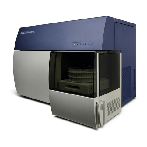
BD FACSymphony A5 SE User manual

BD FACSymphony™ A5SE
Flow Cytometer
User's Guide
23-23473(02)
2022-08
English
For Research Use Only

Copyrights
No part of this publication may be reproduced, transmitted, transcribed, stored in retrieval systems, or translated into any language or
computer language, in any form or by any means: electronic, mechanical, magnetic, optical, chemical, manual, or otherwise, without prior
written permission from BD.
The information in this guide is subject to change without notice. BD reserves the right to change its products and services at any time.
Although this guide has been prepared with every precaution to ensure accuracy, BD assumes no liability for any errors or omissions, nor for
any damages resulting from the application or use of this information. BD welcomes customer input on corrections and suggestions for
improvement.
Trademarks and patents
BD, the BD Logo, BDFACSClean, BDFACSDiva, BDFACSFlow, BDFACSymphony, BDHorizonBrilliant, BDHorizon RealYellow, FACS and
Horizon are trademarks of Becton, Dickinson and Company or its affiliates. All other trademarks are the property of their respective owners.
© 2022 BD. All rights reserved.
For US patents that may apply, see bd.com/patents.
Alexa Fluor™ is a trademark of Life Technologies Corporation.
CF™ is a trademark of Biotium, Inc.
Cy™ is a trademark of GE Healthcare. Cy™ dyes are subject to proprietary rights of GE Healthcare and Carnegie Mellon University, and are
made and sold under license from GE Healthcare only for research and in vitro diagnostic use. Any other use requires a commercial
sublicense from GE Healthcare, 800 Centennial Avenue, Piscataway, NJ 08855-1327, USA.
Regulatory information
For Research Use Only. Not for use in diagnostic or therapeutic procedures.
Laser safety information
Class 1 Laser Product.
FCC information
WARNING: Changes or modifications to this unit not expressly approved by the party responsible for compliance could void the user’s
authority to operate the equipment.
NOTICE: This equipment has been tested and found to comply with the limits for a Class A digital device, pursuant to Part 15 of the FCC
Rules. These limits are designed to provide reasonable protection against harmful interference when the equipment is operated in a
commercial environment. This equipment generates, uses, and can radiate radio frequency energy and, if not installed and used in
accordance with the instruction manual, may cause harmful interference to radio communications. Operation of this equipment in a
residential area is likely to cause harmful interference in which case the user will be required to correct the interference at his or her own
expense. Shielded cables must be used with this unit to ensure compliance with the Class A FCC limits. This Class A digital apparatus meets
all requirements of the Canadian Interference-Causing Equipment Regulations. Cet appareil numérique de la classe A respecte toutes les
exigences du Réglement sur le matériel brouilleur du Canada.
History
Revision Date Change made
23-23473-00 2021-07 Initial release
23-23473(01) 2021-12 In topic Spectral function overview (page 48), corrected UVchannel A filter
bandpass value. Extended list of commercial dyes and the appropriate laser
detectors to use with them.
Changed laser delay ordering and associated delay-optimization procedure.
23-23473(02) 2022-08 Updated UVlaser information to indicate that the laser emission frequency
can be 349nm or 355nm.
Updated table of detectors used with common dyes in Spectral function
overview (page 48)
Updated screenshots to reflect user interface enhancements.
Contents
BD FACSYMPHONY™ A5SE 1
1 ABOUT THIS GUIDE 7
What this guide covers 8
Conventions 8
About the documentation 9
Instrument technical support 10
2 INTRODUCTION 11
System overview 12
Cytometer overview 12
Control panel 14
Fluidics system 15
Sheath and waste containers 19
Optics 20
Workstation 22
3 CYTOMETER SETUP 23
Starting the cytometer and computer 24
Preparing the sheath container 25
Removing air bubbles 27
Preparing the waste container 29
Preparing the fluidics 31
Adding a bead lot number 32
Custom configurations and baselines 34
4 MAINTENANCE 35
Maintenance overview 36
Cleaning the fluidics 37
Shutting down the cytometer 38
Flushing the system 38

Replacing the waste container cap 40
Changing the sheath filter 41
Changing the Bal seal 42
Changing the sample tube O-ring 44
Cleaning or replacing the sheath gasket 45
5 SPECTRAL FUNCTIONS 47
Spectral function overview 48
Autofluorescence 54
Spectral unmixing software considerations 55
Setting up a new spectral experiment 57
Creating a Spectral Unmixing matrix 59
Recording and analyzing spectral data 62
Repeating a spectral experiment 65
6 OPTIMIZING CYTOMETER SETTINGS 67
Cytometer settings workflow 68
Verifying the configuration and user preferences 69
Running a performance check 71
Setting up a compensation experiment 74
Creating application settings 77
Recording compensation controls 78
Calculating compensation 81
7 RECORDING AND ANALYZING DATA 83
Data recording and analysis workflow 84
Preparing the workspace 84
Recording data 85
Analyzing data 87
Reusing an analysis 91
8 MANUAL SETTINGS 93
About laser delay 94
Optimizing laser delay 95
Adjusting area scaling 97
9 TROUBLESHOOTING 103
Cytometer troubleshooting 104
Electronics troubleshooting 109
10 SUPPLIES AND CONSUMABLES 111
Ordering information 112
Beads 112
Reagents 113
4BD FACSymphony™ A5 SE User's Guide

BD FACSymphony™ A5 SE User's Guide

What this guide covers
This guide describes the procedures necessary to operate and maintain the BDFACSymphony™A5SE Special
Order Research Product (SORP) flow cytometer.
Because many cytometer functions are controlled by BDFACSDiva™ software, this guide also contains
information about software features required for basic cytometer setup and operation.
This guide assumes you have a working knowledge of basic Microsoft® Windows® operation. If you are not
familiar with the Windows operating system, see the documentation provided with your computer.
Conventions
Introduction
The following table lists the safety symbols used in this guide to alert you to potential hazards.
Safety symbols
Symbol1Description
Caution alert.
Identifies a hazard or unsafe practice that could result in data loss, material damage, minor injury, severe
injury, or death.
Electrical hazard
Biological hazard
Laser hazard
8BD FACSymphony™ A5 SE User's Guide

About the documentation
Introduction
This topic describes the documentation available with the BDFACSymphony™A5SE flow cytometer.
The following list includes the available documentation for the system.
lBDFACSDiva™ Software Reference Manual: Includes instructions or descriptions for installation and setup,
workspace components, acquisition controls, analysis tools, and data management. Access this manual from
the BDFACSDiva™ Software Help menu (Help > Documentation > Reference Manual), or by double-clicking
the shortcut on the desktop.
lBD®Cytometer Setup and Tracking Application Guide: Describes how to use the BD®Cytometer Setup and
Tracking (CS&T) features in BDFACSDiva™ software.
lBDFACSymphony™A5SE Flow Cytometer Site Preparation Guide contains specifications for:
oCytometer weight and size
oTemperature and other environmental requirements
oElectrical requirements
lBDFACSymphony™A5SE Flow Cytometer Safety and Limitations: Provides descriptions of safety and
warning labels, general system hazards, specific risks, and laser, electrical, and biological hazards.
lBD®High Throughput Sampler User’s Guide: Describes how to set up and operate the BD®High Throughput
Sampler (HTS) option. It also contains a description of BDFACSDiva™ software features specific to the HTS.
lBDFACSFlow™ Supply System User’s Guide: Describes the optional automated sheath and waste fluid control
system.
Publication formats
This guide is provided in PDF format to provide an eco-friendly option.
Chapter 1 About this guide 9

Instrument technical support
Introduction
This topic describes how to get technical assistance.
Contacting technical support
If technical assistance is required, contact your local BDBiosciences customer support representative or
supplier. Go to our website bdbiosciences.com for up-to-date contact information.
When contacting BD Biosciences, have the following information available:
lProduct name, part number, and serial number
lVersion of BDFACSDiva™ software you are using
lAny error messages
lDetails of recent system performance
More information
lWhat this guide covers (page 8)
10 BD FACSymphony™ A5 SE User's Guide

System overview
About the system
The BDFACSymphony™A5SE system includes the flow cytometer, BDFACSDiva™ software v9.3 or later (for
Windows 10) running on the system workstation, the optional BDFACSFlow™ supply system (FFSS), and the
optional BD®High Throughput Sampler (HTS). Each component is described in detail in the following sections.
Number Components
1 Sheath and waste tanks
2 BD FACSymphony™ A5 SE flow cytometer
3 Computer workstation
Cytometer overview
Introduction
The BDFACSymphony™A5SE flow cytometer is an air-cooled multi-laser benchtop instrument with the ability
to acquire parameters for a large number of colors. It uses fixed-alignment lasers that transmit light through a
flow cell to cascadagon detector arrays. These detectors collect and translate the resulting fluorescence signals
into electronic signals. Cytometer electronics convert these signals into digital data.
12 BD FACSymphony™ A5 SE User's Guide

Components
The following figure shows the main components of the instrument. Each component is described in detail in
the following sections.
Number Component Number Component
1 Heat ventilation slots (top) 6 Sample injection port (SIP)
2 Control panel 7 Heat ventilation slots (side)
3 Power button 8 Air and fluidic ports
4 Electrical plug 9 Optics access doors (cacadagon detector arrays)
5 Fluidic sensors
Do not place any objects on top of the instrument. Blocking the ventilation may cause the instrument to
overheat.
Do not place liquids on top of the instrument. Any spill of liquid into the ventilation openings could cause
electrical shock or damage to the instrument.
Chapter 2 Introduction 13

Control panel
Overview
The following figure shows the components in the control panel, which are listed in the table.
Number Component
1 System indicators
2 Fluid control buttons
3 Sample flow rate buttons
4 Sample fine adjust buttons
5 Status screen
6 Mode button
More information
lFluidics system (page 15)
lOptics (page 20)
14 BD FACSymphony™ A5 SE User's Guide

Fluidics system
Introduction
The fluidics system carries the sample out of the sample tube and into the sensing region of the flow cell. Cells
are carried in the sample core stream in single file and measured individually.
System indicators
There are two system indicators (System status and Activity) on the control panel.
lSystem status. Shows the status of the sheath and waste tank levels. The following table describes the LED
indicators, conditions that trigger them, and any action that must be taken.
LED color Status Action
Green Good None
Yellow Sheath and waste tanks need attention. Check tank levels
Red Take immediate action.
lEmpty waste tank
lFill sheath tank
System status is also displayed on the Status screen. See Status screen (page 16) for a description of the
Status screen.
lActivity. Shows whether the cytometer power is on and the status of acquisition. The following table
describes the indicator LEDs, and the status that triggers them.
Indicator LED color Status
Steady pulse Blue Cytometer is powered on.
Fluctuates Blue Cells are passing through the flow cell.
Fluid control
The three fluid control buttons (Run, Standby, and Prime) set the cytometer operation.
lRun Pressurizes the sample tube to transport the sample through the sample injection tube and into the flow
cell.
The Run button is green when the sample tube is on and the support arm is centered. When the tube support
arm is moved left or right to remove a sample tube, the cytometer switches to an automatic standby status
to conserve sheath fluid, and the Run button changes to orange.
lStandby Stops fluid flow to conserve sheath fluid.
When you leave the cytometer for more than a few minutes, place a tube containing 1mL of deionized (DI)
water on the sample injection port (SIP) and press Standby.
lPrime Prepares the fluidics system by draining and filling the flow cell with sheath fluid.
The fluid flow initially stops, and pressure is reversed to force fluid out of the flow cell and into the waste
container. After a preset time, the flow cell fills with sheath fluid at a controlled rate to prevent bubble
formation or entrapment. At completion, the cytometer switches to standby mode.
Chapter 2 Introduction 15

Sample flow rate control
The three flow rate control buttons (LOW, MED, HIGH) set the sample flow rate through the flow cell. The
SAMPLE ADJ buttons allow you to adjust the rate to intermediate levels.
Number Component
1 Status screen
2 Sample flow rate buttons
3 Sample fine adjust buttons
When sample adj is set at the midpoint of 250 (as shown on the status screen on the control panel) the sample
flow rates at the low, med, and high settings are approximately 12, 35, and 60µL/min of sample, respectively.
Each time you press one of the SAMPLE ADJ buttons, the fine adjust of the indicated sample increases or
decreases by 10. The following table shows the approximate sample flow rate range for low, medium, and high.
Settings Sample flow rate (µL/min)
Low 6–24
Med 17.5–70
High 30–120
Status screen
When not in FFSSmode, the first two lines of the status screen show the level of the waste and sheath tanks.
The third line toggles between Fine Adj. and Air Pressure. Status is described in detail in the following table.
16 BD FACSymphony™ A5 SE User's Guide

Item Definition
1Waste level. Shows range (1) from E (empty) to F (full). The display line increases from left to right in sequences
of 20%. System status turns yellow at 80%, and red at 100% full.
2Sheath level. Shows range from E to F. The display line decreases from right to left in sequences of 20% from
full level. System status turns yellow at 20%, and red at 0%.
3Fine Adj. Shows the current setting of fine adjust. Fine adjust can be set in increments of 10 from 0 to 500. The
last value persists, even after cytometer shutdown.
Air pressure. Shows the air pressure as either greater than (>) 5.4 psi, or less than (<) 5 psi. To display psi, press
the Mode button, followed by the Up button.
4FFSS Mode. Shows that the cytometer is in FFSS mode. To enter this mode, press the MODE button 4times.
After you reach FFSS OFF, push the SAMPLE ADJ button once. You should now see the panel display FFSS ON. To
exit, press the MODE button 4 times, then SAMPLE ADJ button once. Repeat the process to turn FFSS mode off.
Fluidic alarms and the Mode button
The fluidic alarms are triggered by the waste and sheath fluid levels in the tanks. The alarms sound when the
waste tank is nearly 100% full and the sheath tank is empty.
To silence the alarm, press the Mode button, then press the Down button. The Mode button flashes to indicate
the cytometer is in silent mode. Repeat this sequence to turn off silent mode.
Note: When the cytometer is in FFSS mode, the alarms are deactivated.
Sample injection port
The SIP is where the sample tube is installed. The SIP includes the sample injection tube and the tube support
arm. Samples are introduced through a stainless steel injection tube equipped with an outer droplet
containment sleeve. The sleeve works in conjunction with a vacuum pump to eliminate droplet formation of
sheath fluid as it backflushes from the sample injection tube.
Chapter 2 Introduction 17

Key Description
1 Tube support arm
2 Outer sleeve
3 Sample injection tube
Sample injection tube
Stainless steel tube that carries sample from the sample tube to the flow cell. This tube is covered with an outer
sleeve that serves as part of the droplet containment system.
Tube support arm
Arm that supports the sample tube and activates the droplet containment system vacuum. The vacuum is on
when the arm is positioned to the side and off when the arm is centered.
Note: If a sample tube is left on the SIP with the tube support arm to the side (vacuum on), the sample will be
aspirated into the waste container.
Cautions when using the HTS option
When using the flow cytometers with the HTS, ensure that the HTS is completely pushed into the operating
position before removing the droplet containment module (DCM) sleeve or disconnecting the sample coupler
from the SIP. This is to avoid accidental leakage of potentially biohazardous liquids directly onto the instrument.
With the HTS in the proper location, the containment dish with padding is directly below the SIP.
If you are using the HTS option, always slide the HTS mount slowly to prevent sample cross-contamination when
the wells are full. Never move the HTS when it is in operation.
Do not lean on or put any weight on the HTS as it could damage the instrument.
18 BD FACSymphony™ A5 SE User's Guide

Droplet containment module
The droplet containment module (DCM) prevents sheath fluid from dripping from the SIP and provides
biohazard protection.
Note: The DCMwill not run when the HTS selector switch is in Plate Mode.
When no sample tube is installed on the SIP, sheath fluid backflushes through the sample injection tube. This
backflush helps prevent carryover of cells between samples. The DCM vacuum is activated when the sample
tube is removed and the tube support arm is moved to the side. Sheath fluid is aspirated as it backflushes the
sample injection tube.
Sheath and waste containers
Introduction
This topic describes the sheath and waste containers. The sheath and waste containers are outside the
cytometer and are positioned on the floor. The sheath and waste containers should remain in the installed
position. Moving them to a different height (for example, from the floor to a bench) changes the flow rate.
Note: If you are using the FFSS, see the BDFACSFlow™ Supply System User’s Guide.
Sheath container
The sheath container has a capacity of 10L. Sheath fluid is filtered through an in-line, interchangeable filter
that prevents small particles from entering the sheath fluid lines. An alarm sounds when the container is empty.
Do not fill the sheath tank to its maximum capacity. When an overfull tank is pressurized, erratic cytometer
performance can result.
Waste container
The waste container has a capacity of 10L. An alarm sounds when the container is full. If the waste container
overfills, install a replacement waste tank cap and baffle.
More information
lPreparing the sheath container (page 25)
lPreparing the waste container (page 29)
lStatus screen (page 16)
lFluidic alarms and the Mode button (page 17)
Chapter 2 Introduction 19

Optics
Introduction
This topic describes the optical components for the BDFACSymphony™A5SE flow cytometer including:
lDetector arrays
lLaser options
lOptical filters
lSignal detectors
Detector arrays
The detector arrays consist of cascadagon arrays. Each cascadagon is outfitted with 2 to 20 PMTs and can
detect the corresponding number of signals.
Laser options
The flow cytometers can be configured with up to 10 lasers. The following table lists the lasers:
Laser Wavelength (nm) Power (mW)
Violet 405 200
Blue 488 150
UV 349 or 355 60
Yellow Green 561 150
Red 637 140
Optical filters
Optical filters attenuate light or help direct it to the appropriate detectors. The name and spectral
characteristics of each filter appear on its holder.
There are two types of optical filters in the BDFACSymphony™A5SE flow cytometer:
lLongpass dichroic mirrors (LPs) Transmit wavelengths that are longer than the specified value and reflect
all light below the specified wavelength.
lBandpass filters (BPs) Pass a narrow spectral band of light.
When dichroic filters are used as steering optics to direct different color light signals to different detectors, they
are called dichroic mirrors. LP dichroic mirrors transmit longer wavelengths to one detector while reflecting
shorter wavelengths to a different detector.
20 BD FACSymphony™ A5 SE User's Guide
Table of contents
Other BD Medical Equipment manuals

BD
BD Kiestra ReadA User manual

BD
BD BodyGuard Small Lockbox User manual

BD
BD BD FACSPresto User manual

BD
BD EnCor Enspire User manual

BD
BD Alaris GP Manual

BD
BD Microtainer Quikheel User manual

BD
BD Halo One Series User manual

BD
BD Vacutainer Pronto Reference guide

BD
BD PureWick PW200E Operating and maintenance manual

BD
BD FACSAria Manual