SUPERSCAN
USER’S GUIDE
PRESENCE SENSOR
DESCRIPTION The SuperScan (10SSI, 10SSII, 10SSIII) detector is a door-mounted presence detection system that is used on automatic
pedestrian swing doors. The SuperScan can be used on an SMR or non-SMR system. Unlike other door-mounted sensing
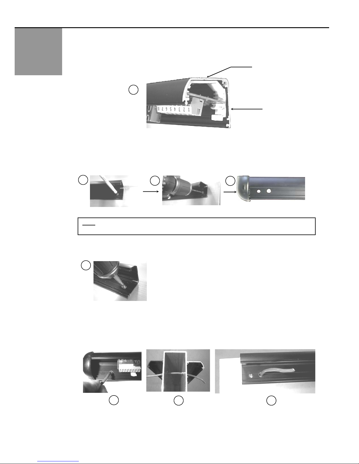
devices, the SuperScan's unique electronic architecture allows the detection modules to be mounted near the top of the
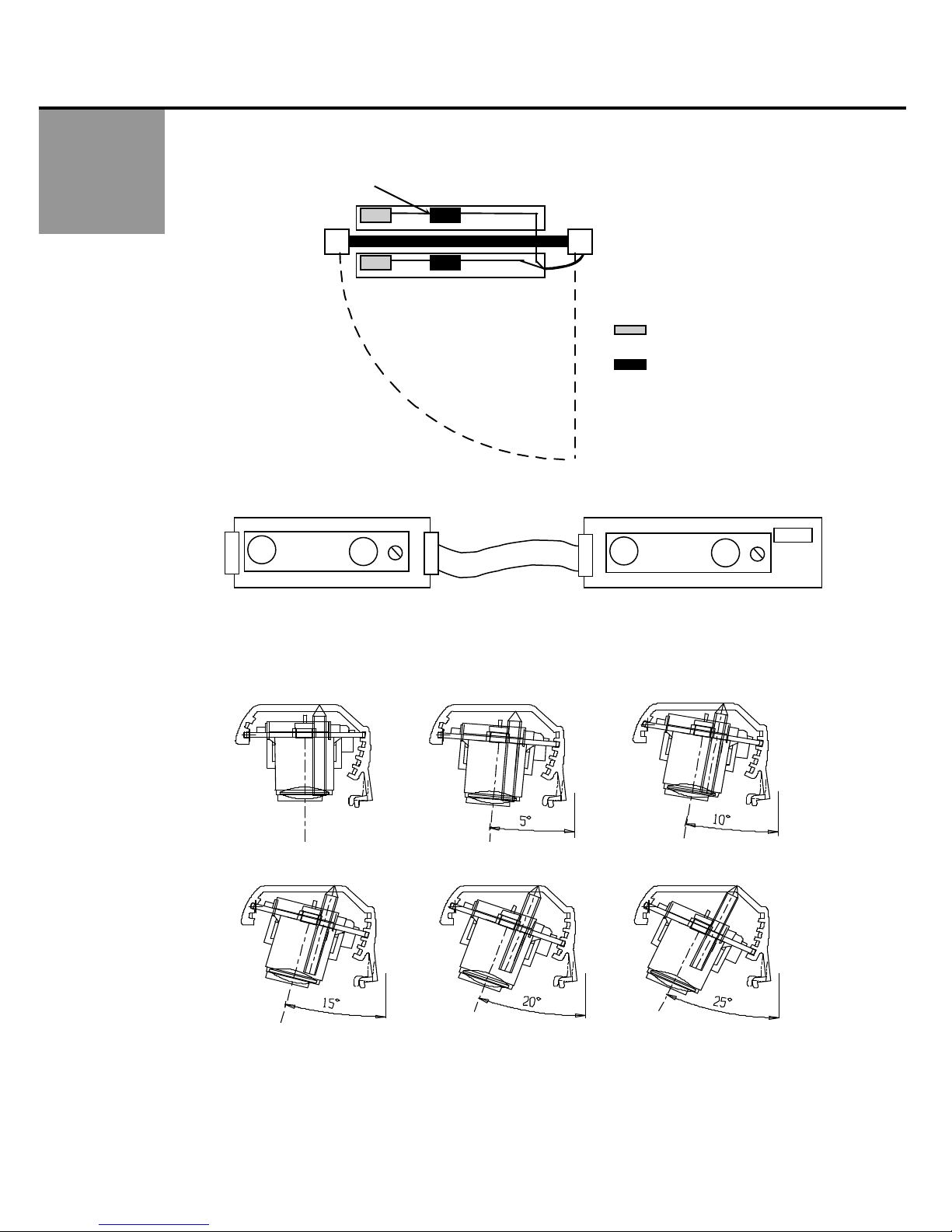
door, out of harm's way. A rotating cam is used for the range adjustment of the detection zone. Width patterns may be
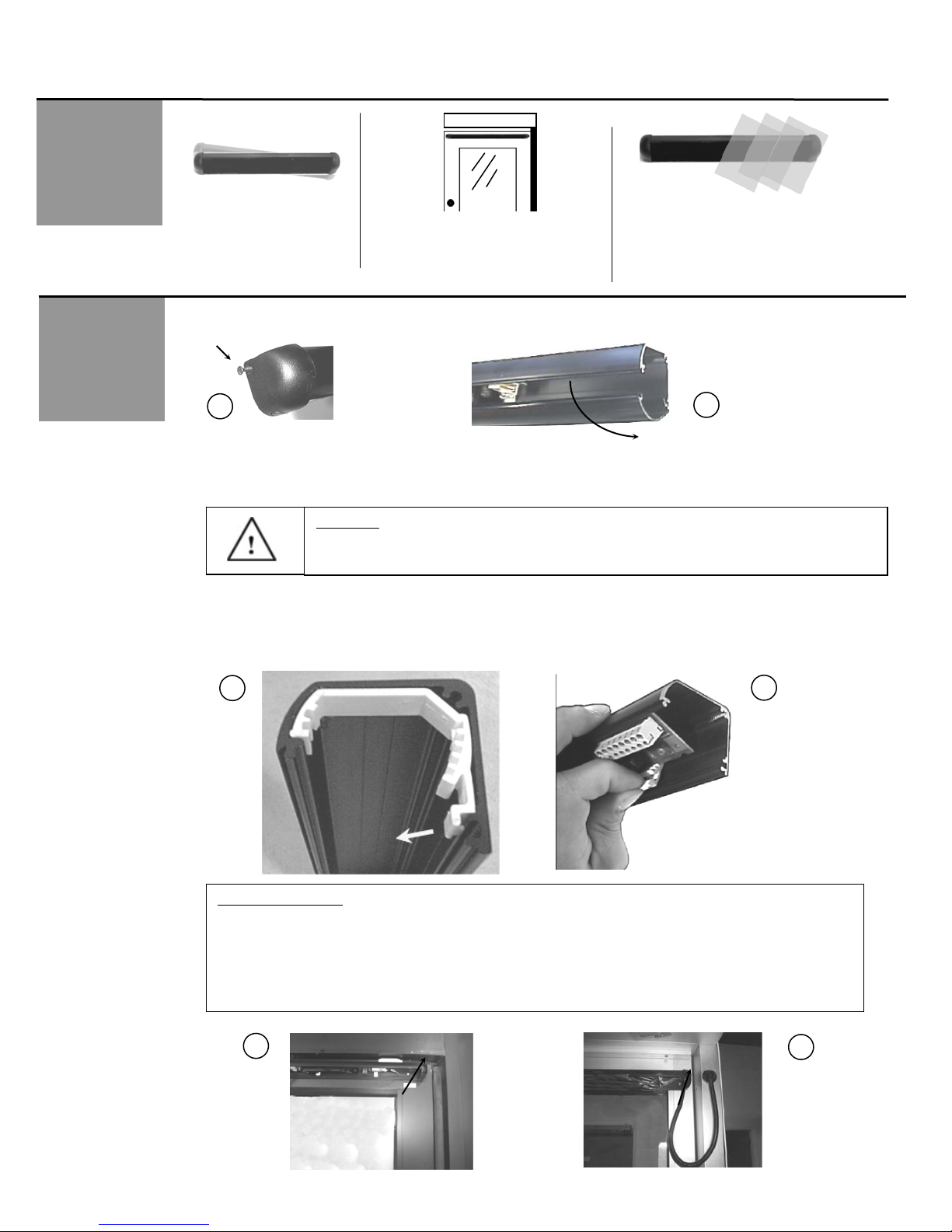
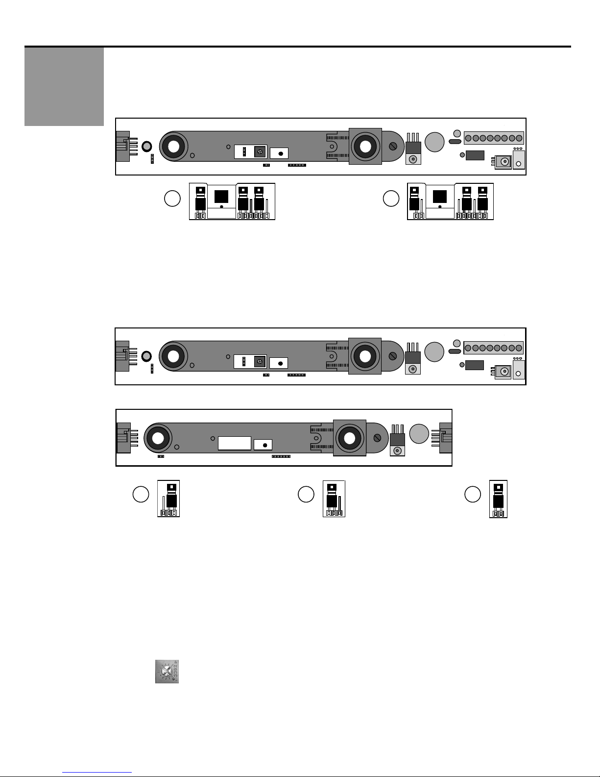
altered by adding slave modules to the master module. These slave modules are simply added by inserting them into the
aluminum extrusion, then connecting them with the attached flat ribbon cable to the next module without interrupting other
modules in the same extrusion. Once installed, the detection zone (in addition to being adjustable for distance) can be
angled independently from the other modules.
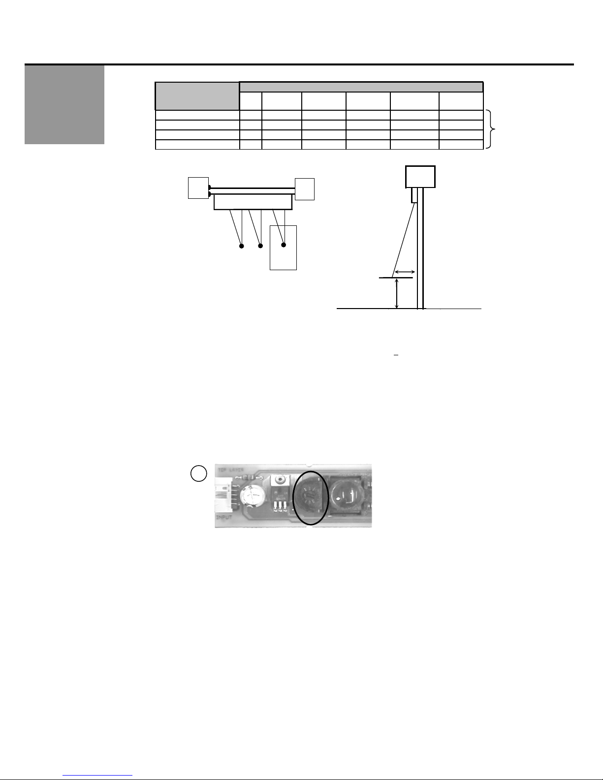
Each SuperScan module consists of two optics, a transmitter (TX) and a receiver (RX), and functions independently of the
other modules. The transmitter emits an extremely precise beam, which measures approximately 4" in diameter at a
distance of 8'. The receiver, in turn, receives the infrared beam reflected off of the floor. This transmission and reception
forms a detection triangle, which is the basic premise of detection (called triangulation). Should this angle be interrupted,
detection will occur. Detection is NOT based upon the intensity of the beam, and in principle will not be affected by the color
or background of the object that interrupts the angle.
TECHNIC
SPECIFICATIONS DESCRIPTION SPECIFICATION
Power Supply 12 to 24 VAC ± 10% / 12 to 24 VDC +10%
Current Consumption:
Master: On = 60 mA max. / Master: Off = 30 mA max.
Slave: On = 40 mA. Max. / Slave: Off = 30 mA max.
Input Inhibit 12 to 24 VAC ± 10%: / 12 to 24 VDC +10% / Inhibited when voltage is applied
SMR Input Data 12-18 VDC: Inhibited when voltage is applied
Output Interface; relay Relay; max. contact rating is 1A @ 30v ( resistive)
Detection Range 0' to 8'
Distance Adjustment 2’ to 8’ / Rotating cam with linear adjustment
Max. Mounting Height 8’
Detection Time < 50 ms
Detection Signal Duration Infinite Presence Detection
Output Hold Time Potentiometer Range: 0.1 to 4.5 seconds.
LED Indications Master: Red LED = Detection
Green LED = Active Output
Slave: Red LED = Detection
Operating Temperature
Range
-30° F to 140° F
PCB Dimensions Master: 10.91" x 1.5"
Slave: 8.75" x 1.5"
Connection to Door
Controller
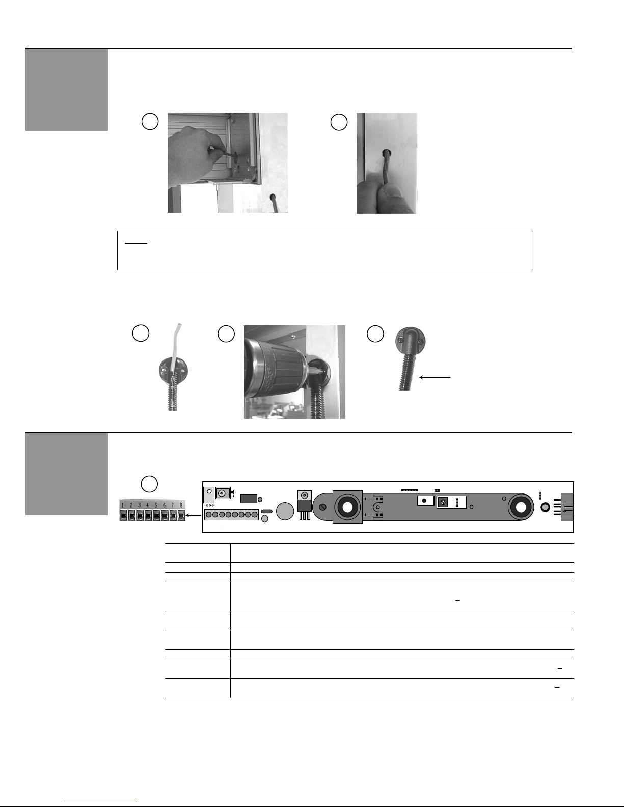
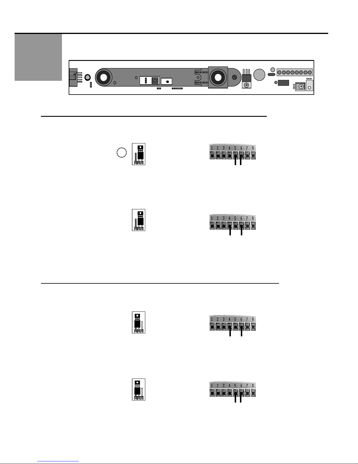
8 Position Screw Terminal on Master PCB
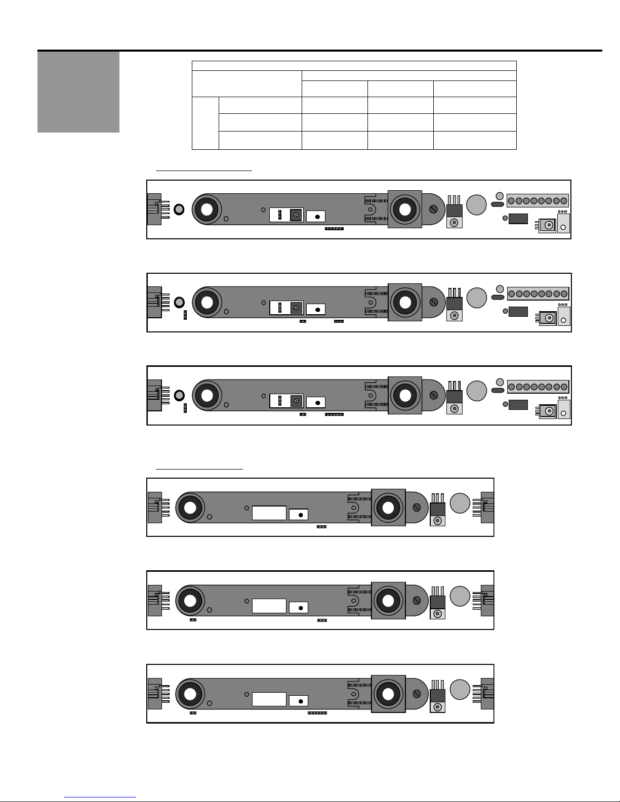
Connection: Master to
Slave
Flat Ribbon Cable With Connectors and Key Lock
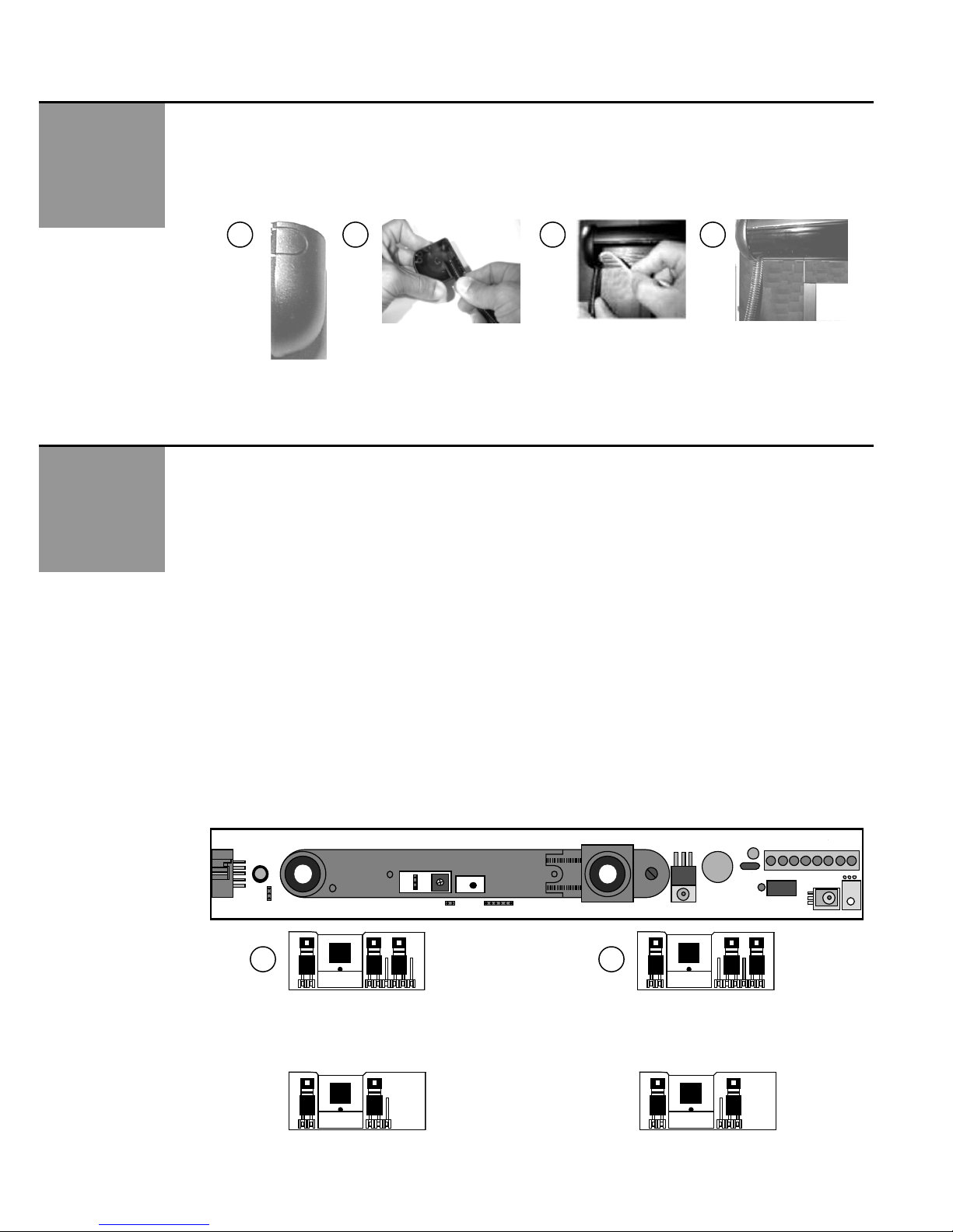
Max. Number of Slaves Standard = 9 / With Monitoring = 8 max.
Functions Selection Detection Mode - NO or NC
Normal Mode or Background Analysis Mode
75.0084.05 20110720 Page 1 of 17
•Shut off all power going to the header before attempting any wiring procedures.
•Maintain a clean & safe environment when working in public areas.
•Constantly be aware of pedestrian traffic around the door area.
•Always stop pedestrian traffic through the doorway when performing tests that may result in unexpected
reactions by the door.
•Always check placement of all wiring and components before powering up to ensure that moving door parts
will not catch any wires and cause damage to equipment.
•Ensure compliance with all applicable safety standards (i.e. ANSI A156.10, 156.27) upon completion of
installation.
SAFETY
PRECAUTIONS
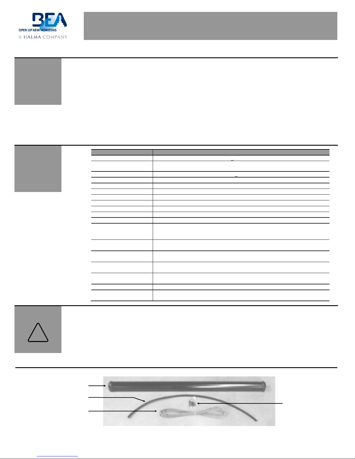
Jamb Hole Cover
SuperScan Assembly
Wire Transfer Sheath
8-Wire Cable