Installation and Technical Information
BEGA
Accessories
Please refer to the appropriate
accessory installation sheet for
further instruction when applicable.
Replacement Parts
In the interest of product improvement, BEGA reserves the right to make technical changes without notice.
BEGA 1000 Bega Way, Carpinteria, CA 93013 (805)684-0533 Fax (805)566-9474 www.bega-us.com © Copyright BEGA-US 2017
LED Bollard 88 066
Tools Required:
Adjustable wrench
1/2” nut driver
3mm hex key
4mm hex key
5mm hex key
Protection Class: IP 65
Weight: 20.3 lbs.
Relamping/Maintenance
No relamping required.
Lamp: 7.9W LED
88 066
6/21/2017
Page 1 of 2
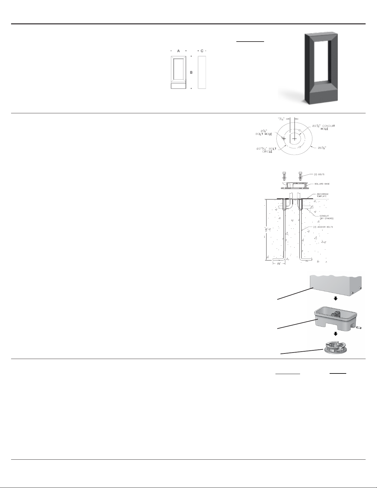
Anchorage 79 817
Notice to Installer for 88 066:
1. See page 2 for specic product safety warnings.
2. Fixture may be damaged if connected to conduit systems that contain water - Article 300-5G of
the National Electric Code requires that “Conduits or raceways through which moisture may contact
energized live parts shall be sealed or plugged at either or both ends.”
3. 79 817 anchorage kit (included) must be installed in concrete pad/foundation.
4. It is recommended that when installing in planting areas the bollard base be slightly elevated to
avoid prolonged submerging during heavy rains.
5. Wet location listing does not imply suitability for exposure to standing water for long periods of time.
6. LEDs are high-quality electronic components! Please avoid touching the light
output opening of the LED directly during installation.
79 817 anchorage installation:
1. Provide means to bring supply wiring to the bollard in accordance with local code. The template has
a 2-3/8” conduit hole for conduit entry.
2. Assemble anchorage kit. Unscrew the (3) hex bolts from the female couplers. Remove each hex
bolt and washer. Align each anchor bolt with the hole in the template. Attach each anchor bolt to
the template by replacing the washer and hex bolt and tightening.
3. Determine the nished grade for the application. Use leveling hardware to adjust template to
desired nished height after pouring.
4. Install anchorage kit using either method:
A. Attach template to forming or cross bracing using the (2) nail holes
provided in the template. Level template properly. Pour concrete.
B. Insert anchorage assembly into poured concrete. Concrete must be
vibrated to ensure proper anchorage setting. Level template properly.
88 066 installation:
1. Remove (3) hex bolts and washers, once anchorage is set.
2. Leave template in place to provide a smooth, at surface to mount the base.
3. Loosen (4) 4mm set screws on lower side of xture main casting to remove the main casting from
lower casting. NOTE: The lower casting resides inside the main casting and connects directly to
the bollard base.
4. Loosen the 5mm set screw on the lower casting and remove the bollard base.
5. Align bollard base holes with anchorage holes.
6. Bolt the bollard base to the anchorage kit using the (3) hex bolts and washers.
7. Make supply wiring connections to wire leads from driver inside the xture
MAIN VOLTAGE SUPPLY WIRE TO BLACK LUMINAIRE WIRE;
NEUTRAL (COMMON) SUPPLY WIRE TO WHITE LUMINAIRE WIRE;
GREEN GROUND WIRE TO GREEN LUMINAIRE WIRE.
Dimming (if applicable):
DIMMING CONTROL WIRE (+) TO POSITIVE DRIVER DIM CONTROL WIRE
DIMMING CONTROL WIRE (-) TO NEGATIVE DRIVER DIM CONTROL WIRE
8. Place the lower casting over the bollard base so that the (3) notches in the bollard base align with the lower
casting and orient correctly. Attach together by tightening the 5mm set screw.
9. Secure the bollard by tightening the (4) 4mm set screws at the base of the main casting.
Dimensions
A: 10-5/8 “
B: 28-1/8 “
C: 5-1/4 “
Description
Lens
Driver (120V-277V)
LED (3000K)
LED (4000K)
Part No
Consult factory
75983-02
LED-0322/930
LED-0322/940
Figure 1
Figure 2: Anchorage Assembly
Figure 3: Generic Image
Main Casting
Lower Casting
Bollard Base


