manuals.online logo
Brands
  1. Home
  2. •
  3. Brands
  4. •
  5. BEGA
  6. •
  7. Outdoor Light
  8. •
  9. BEGA 84 239 Manual

BEGA 84 239 Manual

Installation and Technical Information
BEGA
Due to the dynamic nature of lighting products and the associated technologies, luminaire data on this sheet is subject to change at the discretion of BEGA North America. For the most current technical data, please refer to bega-us.com
BEGA 1000 Bega Way, Carpinteria, CA 93013 (805)684-0533 © copyright BEGA 2021
Figure 1:
Figure 2:
Overview:
LED Watts: 11.5W
System Watts: 18.0W
Controllability: 0-10V, TRIAC, and ELV dimmable
Weight: 13.9 lbs.
Protection Class: IP65
Tools Required:
• 5mm hex head screwdriver
• Adjustable wrench
Shielded Bollard - Asymmetric 84 239
Dimensions
A: 7-1/2”
B: 39-3/8”
Maintenance:
Clean regularly with solvent-free cleaner
removing dirt and debris. Do not use high
pressure cleaners.
Replacement Parts
See label inside of xture for LED replacement
part number.
Consult factory for all other replacement
components.
Accessories
Please refer to the appropriate accessory installation
sheet for further instruction when applicable.
Updated: 03/02/21
84 239 1 of 3
AA
B
B
A
STANDARD FIXTURE INSTALLATION (SEE PAGE 2 FOR OPTIONS)
Notice to Installer:
1. See page 3 for specic product safety warnings.
2. Fixture may be damaged if connected to conduit systems that contain water - Article
300-5G of the National Electric Code requires that “Conduits or raceways through which
moisture may contact energized live parts shall be sealed or plugged at either or both
ends.”
3. 79817 anchorage kit (included) must be installed in concrete pad/foundation.
4. It is recommended that when installing in planting areas the bollard base be slightly
elevated to avoid prolonged submerging during heavy rains.
5. Wet location listing does not imply suitability for exposure to standing water for long
periods of time.
6. LEDs are high-quality electronic components! Please avoid touching the light
output opening of the LED directly during installation.
79817 Anchor Kit Installation:
1. Provide means to bring supply wiring to the bollard in accordance with local code. The
template has a 2-3/8” conduit hole for conduit entry.
2. Assemble anchorage kit. Unscrew the (3) hex bolts from the female couplers. Remove
each hex bolt and washer. Align each anchor bolt with the hole in the template. Attach
each anchor bolt to the template by replacing the washer and hex bolt and tightening.
3. Determine the nished grade for the application. Use leveling hardware to adjust template
to desired nished height after pouring.
4. Install anchorage kit using either method:
A. Attach template to forming or cross bracing using the (2) nail holes provided in
the template. Level template properly. Pour concrete.
B. Insert anchorage assembly into poured concrete. Concrete must be vibrated to
ensure proper anchorage setting. Level template properly.
84239 Luminaire Installation:
1. Remove (3) hex bolts and washers, once anchorage is set.
2. Leave template in place to provide a smooth, at surface to mount the base.
3. Turn the base plate and remove from bollard, after loosening the 5mm set screw.
4. Align base plate holes with anchorage holes.
5. Bolt the base plate to the anchorage kit using the (3) hex bolts and washers
6. Make supply wiring connections to wire leads from driver inside the xture
MAIN VOLTAGE SUPPLY WIRE TO BLACK LUMINAIRE WIRE;
NEUTRAL (COMMON) SUPPLY WIRE TO WHITE LUMINAIRE WIRE;
GREEN GROUND WIRE TO GREEN LUMINAIRE WIRE.
Dimming (if applicable):
DIMMING CONTROL WIRE (+) TO POSITIVE DRIVER DIM CONTROL WIRE
DIMMING CONTROL WIRE (-) TO NEGATIVE DRIVER DIM CONTROL WIRE
7. Place the bollard over the base plate so that the (3) notches in the base plate align with
the top.
8. Secure the bollard by tightening the 10mm set screw at the base.
3
4
"
6
5
8
"
3
8
" BOLT HOLE
3
15
16
" BOLT CIRCLE
2
3
8
" CONDUIT HOLE
11"
BOLLARD BASE
(NOT INCLUDED
IN ANCHOR KIT)
ANCHOR TEMPLATE
(3) ANCHOR BOLTS
(5/16" - 18 X 10")
(3) BOLTS
-
79817
ANCHOR KIT
2/22/2021
REV
PART NO.
SIZE
TYPE:
PROPRIETARY AND CONFIDENTIAL
THE INFORMATION CONTAINED IN THIS DRAWING IS THE SOLE PROPERTY
OF BEGA NORTH AMERICA, INC.
ANY REPRODUCTION IN PART OR AS A WHOLE WITHOUT THE WRITTEN
PERMISSION OF BEGA NORTH AMERICA, INC. IS PROHIBITED.
DATE:
APPROVED:
P (805) 684-0533 - www.bega-us.com
DESCRIPTION:
1000 BEGA Way, Carpinteria, California 93013
B
SHEET 3 OF 4
NOT TO SCALE
DATE
DESCRIPTION
CHANGED BY
REV
Installation and Technical Information
BEGA
Due to the dynamic nature of lighting products and the associated technologies, luminaire data on this sheet is subject to change at the discretion of BEGA North America. For the most current technical data, please refer to bega-us.com
BEGA 1000 Bega Way, Carpinteria, CA 93013 (805)684-0533 © copyright BEGA 2021
Figure 1:
Overview:
LED Watts: 11.5W
System Watts: 18.0W
Controllability: 0-10V, TRIAC, and ELV dimmable
Weight: 13.9 lbs.
Protection Class: IP65
Tools Required:
• 5mm hex head screwdriver
• Adjustable wrench
Figure 2:
Shielded Bollard - Asymmetric 84 239
Dimensions
A: 7-1/2”
B: 39-3/8”
Maintenance:
Clean regularly with solvent-free cleaner
removing dirt and debris. Do not use high
pressure cleaners.
Replacement Parts
See label inside of xture for LED replacement
part number.
Consult factory for all other replacement
components.
Accessories
Please refer to the appropriate accessory installation
sheet for further instruction when applicable.
Updated: 03/02/21
84 239 2 of 3
AA
B
B
A
FIXTURE OPTIONAL INSTALLATION METHODS
Notice to Installer:
1. See page 3 for specic product safety warnings.
2. Fixture may be damaged if connected to conduit systems that contain water - Article
300-5G of the National Electric Code requires that “Conduits or raceways through which
moisture may contact energized live parts shall be sealed or plugged at either or both
ends.”
3. It is recommended that when installing in planting areas the bollard base be slightly
elevated to avoid prolonged submerging during heavy rains.
4. Wet location listing does not imply suitability for exposure to standing water for long
periods of time.
5. LEDs are high-quality electronic components! Please avoid touching the light
output opening of the LED directly during installation.
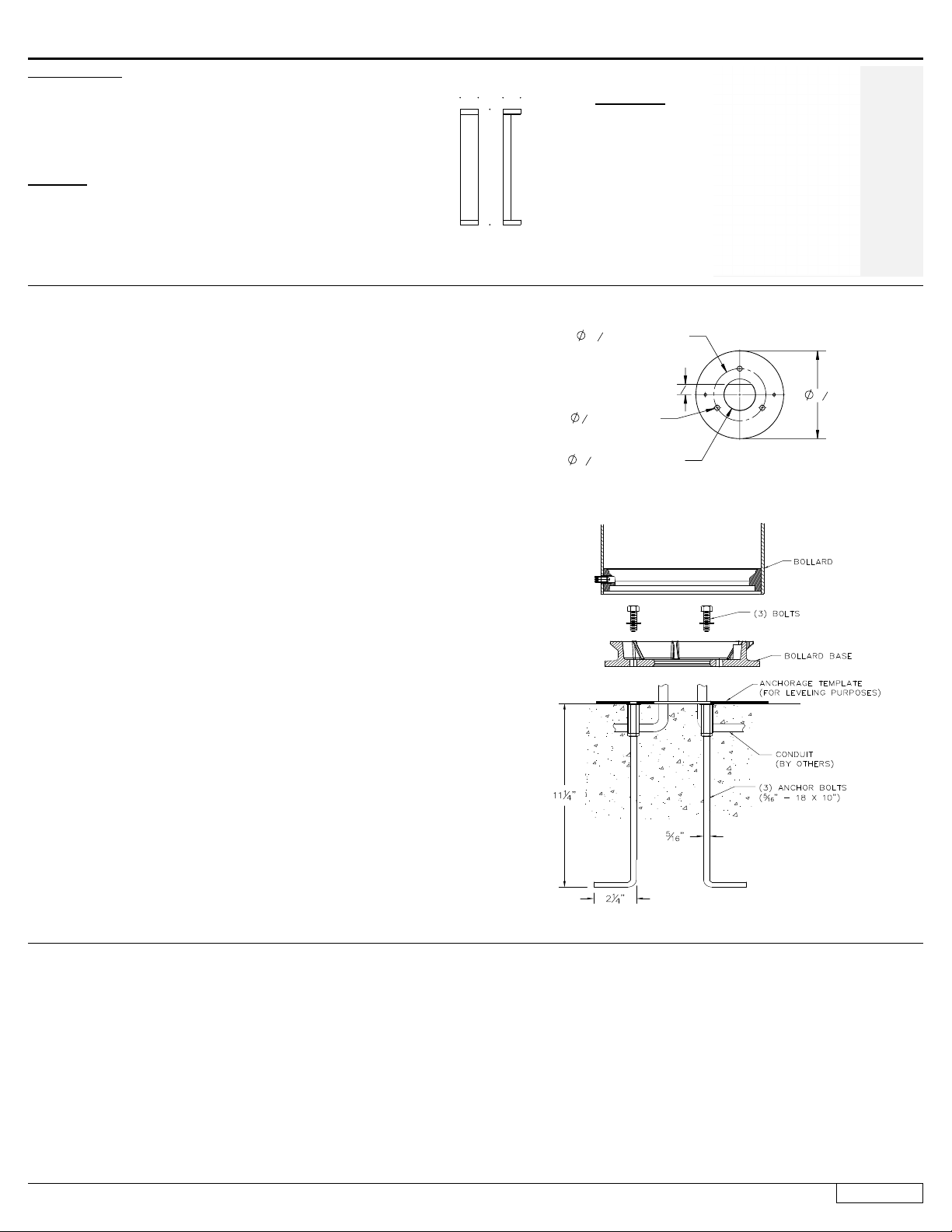
70895 Direct Burial Anchor Kit Installation:
1. Provide means to bring supply wiring to the conduit entry location in accordance with
local code.
2. Prepare soil for anchorage or cast the post in concrete.
3. Make sure anchorage is installed rmly into the ground and mounted level to the surface.
NOTE: ENSURE THAT THE FLANGE PLATE IS ENTIRELY LEVEL AND FLUSH WITH
THE TOP EDGE OF THE SURFACE
4. Remove (3) mounting bolts and washers from the anchorage unit.
5. Align mounting base of the bollard tube, place onto top of anchorage post.
6. Secure by replacing (3) bolts through bollard base, into threaded holes of anchorage
ange. Tighten bolts rmly.
7. Skip to step 6 on 84238 luminaire installation (below)
84239 Luminaire Installation:
1. Remove (3) hex bolts and washers, once anchorage is set.
2. Leave template in place to provide a smooth, at surface to mount the base.
3. Turn the base plate and remove from bollard, after loosening the 5mm set screw.
4. Align base plate holes with anchorage holes.
5. Bolt the base plate to the anchorage kit using the (3) hex bolts and washers
6. Make supply wiring connections to wire leads from driver inside the xture
MAIN VOLTAGE SUPPLY WIRE TO BLACK LUMINAIRE WIRE;
NEUTRAL (COMMON) SUPPLY WIRE TO WHITE LUMINAIRE WIRE;
GREEN GROUND WIRE TO GREEN LUMINAIRE WIRE.
Dimming (if applicable):
DIMMING CONTROL WIRE (+) TO POSITIVE DRIVER DIM CONTROL WIRE
DIMMING CONTROL WIRE (-) TO NEGATIVE DRIVER DIM CONTROL WIRE
7. Place the bollard over the base plate so that the (3) notches in the base plate align with
the top.
8. Secure the bollard by tightening the 5mm set screw at the base.
84239-EMPK Option Luminaire Installation:
1. Follow steps 1-6 above for 84239 luminaire installation.
2. After installation is complete, supply AC power to the emergency driver and join the
converter connection (Figure 2).
3. At this point, power should be connected to both the LED driver and the emergency
driver, and the charging indicator light should illuminate indicating the battery is charging.
4. A short-term test may be conducted after the emergency driver has been charged for one
hour. Charge for 24 hours before conducting a long-term discharge test.
5. Place the bollard over the base plate so that the (3) notches in the base plate align with
the top.
6. Secure the bollard by tightening the 5mm set screw at the base.
Wire Entry
Flange Plate
Installation and Technical Information
BEGA
Due to the dynamic nature of lighting products and the associated technologies, luminaire data on this sheet is subject to change at the discretion of BEGA North America. For the most current technical data, please refer to bega-us.com
BEGA 1000 Bega Way, Carpinteria, CA 93013 (805)684-0533 © copyright BEGA 2021
Product Safety Warnings 84 239:
THIS PRODUCT MUST BE INSTALLED IN ACCORDANCE WITH THE APPLICABLE INSTALLATION CODE BY A PERSON
FAMILIAR WITH THE CONSTRUCTION AND OPERATION OF THE PRODUCT AND THE HAZARDS INVOLVED.
SUITABLE FOR WET LOCATIONS. SUITABLE FOR MOUNTING WITHIN 1.2 m (4ft) OF THE GROUND
MIN 60°C SUPPLY CONDUCTORS.
CE PRODUIT DOIT ÊTRE INSTALLÉ SELON LE CODE D’INSTALLATION PERTINENT, PAR UNE PERSONNE QUI CONNAÎT
BIEN LE PRODUIT ET SON FONCTIONNEMENT AINSI QUE LES RISQUES INHÉRENTS.
CONVIENT AUX EMPLACEMENTS MOUILLÉS. PEUT ÊTRE INSTALLÉ À MOINS DE 1,2 m (4 pi) DU SOL
LES FILS D’ALIMENTATION 60°C MIN.
Product Safety Warnings 84 239 - EMPK ONLY:
THIS LUMINAIRE IS PROVIDED WITH A FACTORY-INSTALLED EMERGENCY LIGHTING BATTERY PACK
CSA C22.2 NO. 141, UNIT EQUIPMENT FOR EMERGENCY LIGHTING
CAUTION-This unit has more than one power supply connection point. To reduce the risk of electric
shock, disconnect both the branch circuit-breakers or fuses and emergency power supplies before
servicing
CAUTION -see instruction manual for installation, operating, and maintenance instructions
CE LUMINAIRE EST ÉQUIPÉ EN USINE D’UNE BATTERIE DES LUMIÈRES D’URGENCE
CSA C22.2 NO. 141 ÉQUIPEMENT POUR UNITÉ D’URGENCE ÉCLAIRAGE
ATTENTION -Cette unité a plus d’un point de connexion d’alimentation. Pour réduire le risque de
choc électrique, débranchez les deux succursales disjoncteurs ou des fusibles et des alimentations
de secours avant l’entretien
ATTENTION -voir le manuel d’instructions pour des instructions, exploitation, entretien
etd’installation
Updated: 03/02/21
3 of 3
84 239
Shielded Bollard - Asymmetric 84 239

Other BEGA Outdoor Light manuals

BEGA 22 202 Manual

BEGA

BEGA 22 202 Manual

BEGA 84 021 User manual

BEGA

BEGA 84 021 User manual

BEGA 24 217 Manual

BEGA

BEGA 24 217 Manual

BEGA 33 200 Manual

BEGA

BEGA 33 200 Manual

BEGA 84 240 Manual

BEGA

BEGA 84 240 Manual

BEGA 71 128 Manual

BEGA

BEGA 71 128 Manual

BEGA 24 013 Manual

BEGA

BEGA 24 013 Manual

BEGA 77 138 User manual

BEGA

BEGA 77 138 User manual

BEGA 84 699 User manual

BEGA

BEGA 84 699 User manual

BEGA 84 245 User manual

BEGA

BEGA 84 245 User manual

BEGA 22 230 User manual

BEGA

BEGA 22 230 User manual

BEGA 84 875 Manual

BEGA

BEGA 84 875 Manual

BEGA 84 315 User manual

BEGA

BEGA 84 315 User manual

BEGA 99 636 User manual

BEGA

BEGA 99 636 User manual

BEGA 33 539 Manual

BEGA

BEGA 33 539 Manual

BEGA 84 607 User manual

BEGA

BEGA 84 607 User manual

BEGA 88 309 Manual

BEGA

BEGA 88 309 Manual

BEGA UniLink 84 824 User manual

BEGA

BEGA UniLink 84 824 User manual

BEGA 84415 Manual

BEGA

BEGA 84415 Manual

BEGA 71 127 Manual

BEGA

BEGA 71 127 Manual

BEGA 7264 User manual

BEGA

BEGA 7264 User manual

BEGA 84 763 User manual

BEGA

BEGA 84 763 User manual

BEGA 84457 Manual

BEGA

BEGA 84457 Manual

BEGA 22 052 Manual

BEGA

BEGA 22 052 Manual

Popular Outdoor Light manuals by other brands

HUBBELL LIGHTING RWL1 installation instructions

HUBBELL LIGHTING

HUBBELL LIGHTING RWL1 installation instructions

Springdale Lighting SPT15128LED Assembly instructions

Springdale Lighting

Springdale Lighting SPT15128LED Assembly instructions

Kichler Lighting IS-DLSL03R-US installation instructions

Kichler Lighting

Kichler Lighting IS-DLSL03R-US installation instructions

Hinkley Lighting 51070 BZ installation instructions

Hinkley Lighting

Hinkley Lighting 51070 BZ installation instructions

Sulion NABIA 200741 manual

Sulion

Sulion NABIA 200741 manual

Quoizel HC1612IB Assembly instruction

Quoizel

Quoizel HC1612IB Assembly instruction

Kogan SMARTERHOME KBE14RGBC1A user guide

Kogan

Kogan SMARTERHOME KBE14RGBC1A user guide

Brooklyn BR-IP65-DP8 quick start guide

Brooklyn

Brooklyn BR-IP65-DP8 quick start guide

Malmbergs JRA2-S30 instruction manual

Malmbergs

Malmbergs JRA2-S30 instruction manual

Quoizel T0251 Assembly and installation instructions

Quoizel

Quoizel T0251 Assembly and installation instructions

Griven Moled 25 user manual

Griven

Griven Moled 25 user manual

IP44.de lix spike solar join Instructions for use

IP44.de

IP44.de lix spike solar join Instructions for use

LUG AVENIDA LED Installation instruction

LUG

LUG AVENIDA LED Installation instruction

LIVARNO LUX HG03444A Assembly, operating and safety instructions

LIVARNO LUX

LIVARNO LUX HG03444A Assembly, operating and safety instructions

superbrightleds WPFCD Series user manual

superbrightleds

superbrightleds WPFCD Series user manual

Homebase BELLANO 632057 instruction manual

Homebase

Homebase BELLANO 632057 instruction manual

STUDIODUE Terra Plus RDM 1733 user manual

STUDIODUE

STUDIODUE Terra Plus RDM 1733 user manual

AFX BAYL2408LAJUD MS Series manual

AFX

AFX BAYL2408LAJUD MS Series manual

manuals.online logo
manuals.online logoBrands
  • About & Mission
  • Contact us
  • Privacy Policy
  • Terms and Conditions

Copyright 2025 Manuals.Online. All Rights Reserved.