manuals.online logo
Brands
  1. Home
  2. •
  3. Brands
  4. •
  5. BEGA
  6. •
  7. Outdoor Light
  8. •
  9. BEGA 22 052 Manual

BEGA 22 052 Manual

Other BEGA Outdoor Light manuals

BEGA UniLink 84 824 User manual

BEGA

BEGA UniLink 84 824 User manual

BEGA 84 696 User manual

BEGA

BEGA 84 696 User manual

BEGA 84 300 Manual

BEGA

BEGA 84 300 Manual

BEGA Gobo 84 987 User manual

BEGA

BEGA Gobo 84 987 User manual

BEGA 84 020 User manual

BEGA

BEGA 84 020 User manual

BEGA 8450 User manual

BEGA

BEGA 8450 User manual

BEGA 44 009 User manual

BEGA

BEGA 44 009 User manual

BEGA 84 875 Manual

BEGA

BEGA 84 875 Manual

BEGA 7264 User manual

BEGA

BEGA 7264 User manual

BEGA 88 066 Manual

BEGA

BEGA 88 066 Manual

BEGA 84 137 User manual

BEGA

BEGA 84 137 User manual

BEGA 84 299 Manual

BEGA

BEGA 84 299 Manual

BEGA 84 991 Series User manual

BEGA

BEGA 84 991 Series User manual

BEGA 77 011 User manual

BEGA

BEGA 77 011 User manual

BEGA 84 700 User manual

BEGA

BEGA 84 700 User manual

BEGA 67 548.2 User manual

BEGA

BEGA 67 548.2 User manual

BEGA Strassburg User manual

BEGA

BEGA Strassburg User manual

BEGA 77 146 User manual

BEGA

BEGA 77 146 User manual

BEGA 24 353 Manual

BEGA

BEGA 24 353 Manual

BEGA 84 253 Manual

BEGA

BEGA 84 253 Manual

BEGA 84 666 User manual

BEGA

BEGA 84 666 User manual

BEGA 85 046 User manual

BEGA

BEGA 85 046 User manual

BEGA Kopenhagen User manual

BEGA

BEGA Kopenhagen User manual

BEGA 71 128 Manual

BEGA

BEGA 71 128 Manual

Popular Outdoor Light manuals by other brands

Sealey LED37 instructions

Sealey

Sealey LED37 instructions

nordlux VEJERS Mounting instruction

nordlux

nordlux VEJERS Mounting instruction

SImx ELITE LED LHTC637 installation instructions

SImx

SImx ELITE LED LHTC637 installation instructions

GEV CAROLINE 10833 manual

GEV

GEV CAROLINE 10833 manual

WE-EF PFL540 LED Installation and maintenance instructions

WE-EF

WE-EF PFL540 LED Installation and maintenance instructions

Lindby 9949029 Intended use

Lindby

Lindby 9949029 Intended use

HEPER DOGO Side LW6048.585-US Installation & maintenance instructions

HEPER

HEPER DOGO Side LW6048.585-US Installation & maintenance instructions

Maretti VIBE S 14.6080.04.A quick start guide

Maretti

Maretti VIBE S 14.6080.04.A quick start guide

HEPER LW8034.003-US Installation & maintenance instructions

HEPER

HEPER LW8034.003-US Installation & maintenance instructions

HEPER MINIMO Installation & maintenance instructions

HEPER

HEPER MINIMO Installation & maintenance instructions

LIGMAN BAMBOO 3 installation manual

LIGMAN

LIGMAN BAMBOO 3 installation manual

Maretti TUBE CUBE WALL 14.4998.04 quick start guide

Maretti

Maretti TUBE CUBE WALL 14.4998.04 quick start guide

Maxim Lighting Carriage House VX 40428WGOB installation instructions

Maxim Lighting

Maxim Lighting Carriage House VX 40428WGOB installation instructions

urban ambiance UQL1273 installation instructions

urban ambiance

urban ambiance UQL1273 installation instructions

TotalPond 52238 instruction manual

TotalPond

TotalPond 52238 instruction manual

Donner & Blitzen 0-02661479-2 owner's manual

Donner & Blitzen

Donner & Blitzen 0-02661479-2 owner's manual

LIGMAN DE-20023 installation manual

LIGMAN

LIGMAN DE-20023 installation manual

Spectroline MAXIMA ML-3500 Series Operator's manual

Spectroline

Spectroline MAXIMA ML-3500 Series Operator's manual

manuals.online logo
manuals.online logoBrands
  • About & Mission
  • Contact us
  • Privacy Policy
  • Terms and Conditions

Copyright 2025 Manuals.Online. All Rights Reserved.

Installation and Technical Information
BEGA
Accessories
Please refer to the appropriate
accessory installation sheet for
further instruction when applicable.
In the interest of product improvement, BEGA reserves the right to make technical changes without notice.
BEGA 1000 Bega Way, Carpinteria, CA 93013 (805)684-0533 Fax (805)566-9474 www.bega-us.com © Copyright BEGA-US 2018
Replacement Parts
Recessed wall- unshielded with white tempered glass 22 052
Tools Required:
3mm and 4mm Hex Key
Philips medium screw driver
Medium slotted screw driver
Protection Class: IP65
Weight: 4.9 lbs.
Dimensions
A: 9-7/8 ”
B: 4-7/8 ”
Relamping/Maintenance
No relamping required.
Lamp: 6W LED Module
22 052
5/16/2018
Page 1 of 2
Description
Faceplate
Gasket (Back housing)
Gear Tray
Part No
FP3038
830879
BP2052LED
Concrete Protection Cover 19 523
Notice to installer for 22 052:
1. BEGA luminaires may be damaged if connected to conduit systems containing water - Article 300-5G
of National Electric Code requires that “Conduits or raceways through which moisture may contact
energized live parts shall be sealed or plugged at either or both ends”.
2. Backbox is Non-IC rated.
3. Suitable for all types of construction including poured concrete construction.
4. Back housing provided with (2) 7/8” holes (horizontal entry) for 1/2” trade size conduit.
5. Back housing must be installed so that the front face is ush with the nished wall.
6. Suitable for through wiring: max. of (4) No. 12 AWG conductors (plus ground) rated for 90° C.
7. Suitable for wasll applications only. (No ceiling and in-grade applications).
8. Integral LED driver supplied with luminaire.
9. LEDs are high-quality electronic components! Please avoid touching the light
output opening of the LED directly during installation.
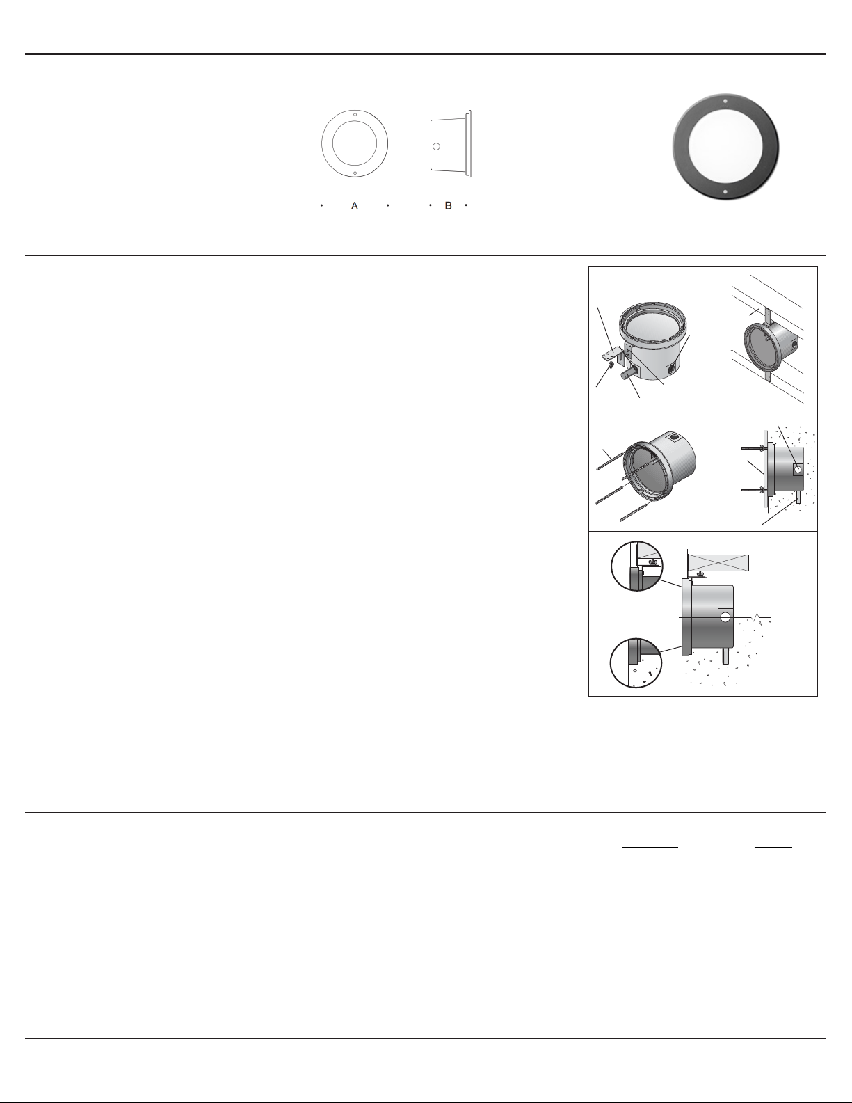
BB2052LED back housing hollow wall (stud) constructioninstallation (2” x 6” min.):
1. Install (2) sets of mounting brackets as shown: Attach the (2) brackets with studs to the housing using (2)
3mm hex head screws. Attach the (2) adjustable L-brackets to the installed brackets using (2) 6-32 wing nuts.
2. Orient back housing as directed on labels. Failure to do so will result in improper installation.
3. Connect conduit to back housing (horizontal) and pull wiring for connections to be made later.
4. Mount back housing to wood or metal blocking so that the front face of the back housing will be ush with the
nished surface. Adjust the brackets by loosening wing nuts if needed.
5. Install splatter guard and nish wall.
6. Place a small bead of silicone between edge of housing and wall to provide seal.
7. Before continuing, remove splatter gaurd and debris from sealing surface.
BB2052LED back housing poured concrete construction installation:
1. Install (4) threaded rods into back housing.
2. Orient back housing as directed on labels. Failure to do so will result in improper installation.
3. Connect the conduit to the back housing (horizontal) and pull wiring for connections to be made later.
4. Attach back housing to form using (4) washers and wing nuts provided so that the front face of the back
housing will be ush with the nished surface.
5. Pour concrete. NOTE: Do not pump or drop concrete directly on top of the back housing.
6. Remove form and install splatter guard to protect during construction.
7. Place a small bead of silicone between edge of housing and wall to provide a seal.
8. Before continuing, remove splatter guard and debris from the sealing surface.
22 052 installation:
1. Orient gear tray as directed on labels.
2. Make supply wiring connections to gear tray wires:
MAIN VOLTAGE SUPPLY WIRE TO BLACK DRIVER WIRE
NEUTRAL (COMMON) SUPPLY WIRE TO WHITE DRIVER WIRE
GREEN GROUND WIRE TO GREEN DRIVER WIRE
Dimming (if applicable):
DIMMING CONTROL WIRE (+) TO POSITIVE DRIVER DIM CONTROL WIRE
DIMMING CONTROL WIRE (-) TO NEGATIVE DRIVER DIM CONTROL WIRE
3. Install gear tray in back housing using (2) 6-32 screws (provided).
4. Install faceplate. Make sure gasket is seated properly. Tighten (2) 4mm hex head screws evenly to secure.

































Installation and Technical Information
BEGA
In the interest of product improvement, BEGA reserves the right to make technical changes without notice.
BEGA 1000 Bega Way, Carpinteria, CA 93013 (805)684-0533 Fax (805)566-9474 www.bega-us.com © Copyright BEGA-US 2018
Recessed wall- unshielded with white tempered glass 22 052
22 052
5/16/2018
Page 2 of 2
Product Safety Warnings:
CAUTION - THIS PRODUCT MUST BE INSTALLED IN ACCORDANCE WITH THE APPLICABLE INSTALLATION CODE BY
A PERSON FAMILIAR WITH THE CONSTRUCTION AND OPERATION OF THE PRODUCT AND THE HAZARDS INVOLVED.
SUITABLE FOR WET LOCATIONS.
MIN 60°C SUPPLY CONDUCTORS.
ATTENTION - CE PRODUIT DOIT ÊTRE INSTALLÉ SELON LE CODE D’INSTALLATION PERTINENT, PAR UNE PERSONNE
QUI CONNAÎT BIEN LE PRODUIT ET SON FONCTIONNEMENT AINSI QUE LES RISQUES INHÉRENTS. CONVIENT AUX
EMPLACEMENTS MOUILLÉS.
LES FILS D’ALIMENTATION 60°C MIN.