manuals.online logo
Brands
  1. Home
  2. •
  3. Brands
  4. •
  5. Behringer
  6. •
  7. Control Unit
  8. •
  9. Behringer 140 DUAL ENVELOPE/ LFO User manual

Behringer 140 DUAL ENVELOPE/ LFO User manual

Quick Start Guide
140 DUAL ENVELOPE/ LFO
Legendary Analog Dual Envelope/LFO
Module for Eurorack
Controls
(1) MANUAL GATE – Press and hold to start the
envelope cycle.
(2) EXT GATE – Connect a gate signal to control the
envelope cycle.
(3) ATTACK TIME – Adjusts the rate at which the envelope
reaches its peak voltage.
(4) DECAY TIME – Adjusts the rate at which the envelope
decays from its peak level to its designated sustain level.
(5) SUSTAIN LEVEL – Controls the level at which the
envelope remains after its peak but before release,
sustaining as long as the input signal is present or the
manual gate switch is held down.
(6) RELEASE TIME – Controls how quickly the envelope
falls after the input signal stops or the manual gate
switch is released.
(7) ENV OUTPUTS – Send up to 2 positive waveforms
and a negative waveform to other modules via these
output connectors.
(8) FREQ RANGE – Sets the oscillating frequency range of the
LFO in 3 steps.
(9) FREQ – Manually sets the oscillating frequency of the LFO.
(10) DELAY – Sets the time from when a trigger signal is
received until the LFO begins operating again.
(11) FREQ CV IN – Accepts voltage for controlling the LFO
frequency with an external source.
(12) TRIGGER - Connect a trigger signal to turn the LFO
o until the end of the trigger cycle. This works along
with the Delay slider, and the LFO recovery takes about
20 seconds. The rear panel features a jumper that can be
removed if you don’t want the LFO to be re-triggered.
(13) OUTPUT LEVEL – Selects between standard or 1/10th
output level for the LFO OUT jacks.
(14) WAVEFORM – Select between sine, triangle,
pulse, sawtooth or reverse sawtooth for the LFO
waveform output.
(15) LFO OUT – Sends the LFO output to other modules.
The upper jack is non-inverting and the lower jacks
is inverting.
Power Connection
The 140 comes with the required power cable for connecting
to a standard Eurorack power supply system. Follow these
steps to connect power to the module. It is easier to make
these connections before the module has been mounted into
a rack case.
1. Turn the power supply or rack case power o and
disconnect the power cable.
2. Insert the 16-pin connector on the power cable into the
socket on the power supply or rack case. The connector has
a tab that will align with the gap in the socket, so it cannot
be inserted incorrectly. If the power supply does not have
a keyed socket, be sure to orient pin 1 (-12 V) with the red
stripe on the cable.
3. Insert the 10-pin connector into the socket on the back of
the module. The connector has a tab that will align with the
socket for correct orientation.
4. After both ends of the power cable have been securely
attached, you may mount the module in a case and turn on
the power supply.
(1)
(3) (4) (5) (6)
(2)
(7)
(8)
(9) (10) (13)
(15)
(14)
(11)
(12)
Installation
The necessary screws are included with the module for mounting
in a Eurorack case. Connect the power cable before mounting.
Depending on the rack case, there may be a series of xed holes
spaced 2 HP apart along the length of the case, or a track that
allows individual threaded plates to slide along the length
of the case. The free-moving threaded plates allow precise
positioning of the module, but each plate should be positioned in
the approximate relation to the mounting holes in your module
before attaching the screws.
Hold the module against the Eurorack rails so that each of the
mounting holes are aligned with a threaded rail or threaded
plate. Attach the screws part way to start, which will allow
small adjustments to the positioning while you get them all
aligned. After the nal position has been established, tighten the
screws down.
Specications
Inputs
Ext gate 3.5 mm jack, DC coupled
Impedance 50 kΩ
Min input level +3 V
Max input level +10 V
Frequency CV input 3.5 mm jack, DC coupled
Impedance 100 kΩ
Max input level +/-10 V
CV scaling 1 V / octave
Ext LFO trigger 3.5 mm jack, DC coupled
Impedance 50 kΩ
Max input level +10 V
Outputs
Envelope 1/2 out 3.5 mm jack, DC coupled
Impedance 1 kΩ
Max output level +/-10 V
LFO output 3.5 mm jack, DC coupled
Impedance 1 kΩ
Max output level 10 V pk-pk
Controls
Attack 1.5 ms - 7.5 s
Decay 4 ms - 15 s
Sustain +/-10 V
Release 4 ms - 15 s
Manual gate switch Envelope cycle start
Frequency range switch LFO low 0.05 - 1.8 Hz,
mid 0.2 - 9 Hz,
high 0.5 - 30 Hz
Frequency LFO frequency,
0.05 Hz - 30 Hz
Delay LFO operation delay, 0 - 7 s
Waveform rotary switch Sine, triangle, pulse,
sawtooth, rev sawtooth
Output level switch 1 V pk-pk, 10 V pk-pk
Power
Power supply Eurorack
Current draw 40 mA (+12 V),
40 mA (-12 V)
Physical
Dimensions 44 x 81 x 129 mm
(1.7 x 3.2 x 5.1")
Rack units 16 HP
Weight 0.18 kg (0.4 lbs)
LEGAL DISCLAIMER
Music Tribe accepts no liability for any loss which may be suered by any
person who relies either wholly or in part upon any description, photograph,
or statement contained herein. Technical specications, appearances and
other information are subject to change without notice. All trademarks are the
property of their respective owners. Midas, KlarkTeknik, Lab Gruppen, Lake,
Tannoy,Turbosound, TC Electronic, TC Helicon, Behringer, Bugera, Auratone
and Coolaudio are trademarks or registered trademarks of MusicTribe
Global Brands Ltd. © Music Tribe Global Brands Ltd. 2019 All rights reserved.
LIMITED WARRANTY
For the applicable warranty terms and conditions and additional information
regarding MusicTribe’s Limited Warranty, please see complete details online
at musictribe.com/warranty.
Zhongshan Eurotec Electronics Limited
No. 10Wanmei Road, South China Modern Chinese Medicine Park,
Nanlang Town, 528451, Zhongshan City, Guangdong Province, China

Other manuals for 140 DUAL ENVELOPE/ LFO

1

This manual suits for next models

1

Other Behringer Control Unit manuals

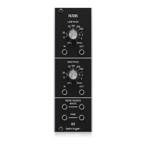
Behringer 923 FILTERS User manual

Behringer

Behringer 923 FILTERS User manual

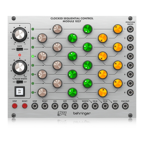
Behringer 1027 User manual

Behringer

Behringer 1027 User manual

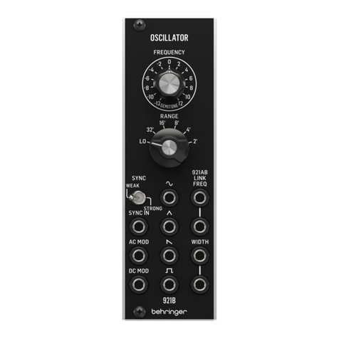
Behringer 921B OSCILLATOR User manual

Behringer

Behringer 921B OSCILLATOR User manual

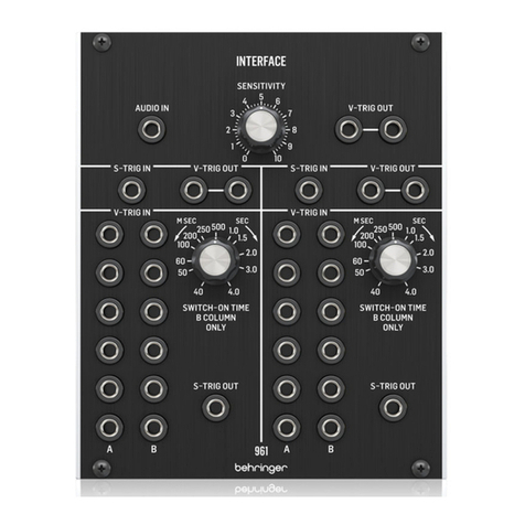
Behringer 961 Interface User manual

Behringer

Behringer 961 Interface User manual

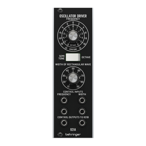
Behringer 921A Oscillator Driver User manual

Behringer

Behringer 921A Oscillator Driver User manual

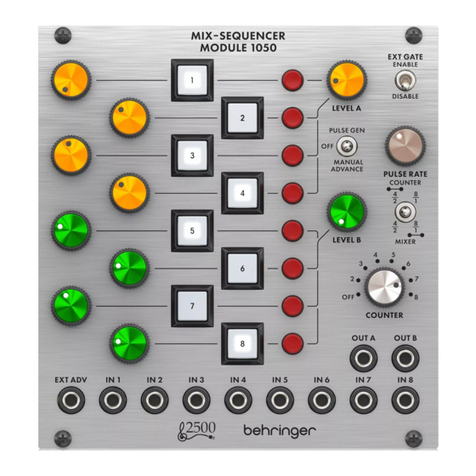
Behringer MIX-SEQUENCER MODULE 1050 User manual

Behringer

Behringer MIX-SEQUENCER MODULE 1050 User manual

Behringer 150 RING MOD/NOISE/S&H/LFO User manual

Behringer

Behringer 150 RING MOD/NOISE/S&H/LFO User manual

Behringer 992 CONTROL VOLTAGES User manual
Behringer

Behringer 992 CONTROL VOLTAGES User manual

Behringer DUAL ENVELOPE GENERATOR MODULE 1003 User manual

Behringer

Behringer DUAL ENVELOPE GENERATOR MODULE 1003 User manual

Behringer 121 DUAL VCF User manual

Behringer

Behringer 121 DUAL VCF User manual

Behringer MODAMP 2500 Series User manual

Behringer

Behringer MODAMP 2500 Series User manual

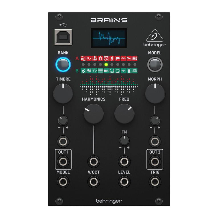
Behringer BRAINS User manual

Behringer

Behringer BRAINS User manual

Behringer 992 CONTROL VOLTAGES User manual

Behringer

Behringer 992 CONTROL VOLTAGES User manual

Behringer 994 MULTIPLES User manual

Behringer

Behringer 994 MULTIPLES User manual

Behringer 112 DUAL VCO User manual

Behringer

Behringer 112 DUAL VCO User manual

Behringer CP3A-O User manual

Behringer

Behringer CP3A-O User manual

Behringer 2500 Series User manual

Behringer

Behringer 2500 Series User manual
Behringer 902 User manual

Behringer

Behringer 902 User manual

Behringer 130 DUAL VCA User manual

Behringer

Behringer 130 DUAL VCA User manual

Behringer 2500 Series User manual

Behringer

Behringer 2500 Series User manual

Behringer 960 SEQUENTIAL CONTROLLER User manual
Behringer

Behringer 960 SEQUENTIAL CONTROLLER User manual

Behringer 2500 Series User manual

Behringer

Behringer 2500 Series User manual

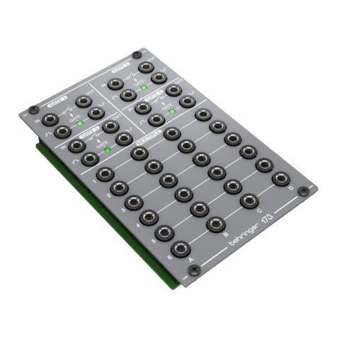
Behringer 173 QUAD GATE/MULTIPLES User manual
Behringer

Behringer 173 QUAD GATE/MULTIPLES User manual

Behringer CP35 Attenuators User manual

Behringer

Behringer CP35 Attenuators User manual

Popular Control Unit manuals by other brands

Ring Engineering AM-1S user manual

Ring Engineering

Ring Engineering AM-1S user manual

Festo CPX-E-1CI manual

Festo

Festo CPX-E-1CI manual

Sporlan Parker S3C Startup guide

Sporlan

Sporlan Parker S3C Startup guide

Monacor ATT-412PEU instructions

Monacor

Monacor ATT-412PEU instructions

Konica Minolta IC-202 quick guide

Konica Minolta

Konica Minolta IC-202 quick guide

Ebyte E180-Z5812SP product manual

Ebyte

Ebyte E180-Z5812SP product manual

Emerson ASCO 290 Series Installation and maintenance instructions

Emerson

Emerson ASCO 290 Series Installation and maintenance instructions

VAT 612 Series Installation, operating,  & maintenance instructions

VAT

VAT 612 Series Installation, operating, & maintenance instructions

Victaulic FireLock NXT 769N Series Installation, Maintenance, and Testing Manual

Victaulic

Victaulic FireLock NXT 769N Series Installation, Maintenance, and Testing Manual

Omron SYSMAC C200H-NC111 Operation manual

Omron

Omron SYSMAC C200H-NC111 Operation manual

Tech Controllers EU-L-X WiFi user manual

Tech Controllers

Tech Controllers EU-L-X WiFi user manual

Phoenix Contact PP-RJ Series datasheet

Phoenix Contact

Phoenix Contact PP-RJ Series datasheet

AERMEC MODUCONTROL Usage manual

AERMEC

AERMEC MODUCONTROL Usage manual

ABB NPBA-12 Installation and startup guide

ABB

ABB NPBA-12 Installation and startup guide

Hirschmann PTN-7-SERIAL user manual

Hirschmann

Hirschmann PTN-7-SERIAL user manual

Reer ARGOLUX AU S3M2 Installation, use and maintenance

Reer

Reer ARGOLUX AU S3M2 Installation, use and maintenance

Nordic nRF52840 manual

Nordic

Nordic nRF52840 manual

Supra Vision PV1100 owner's manual

Supra

Supra Vision PV1100 owner's manual

manuals.online logo
manuals.online logoBrands
  • About & Mission
  • Contact us
  • Privacy Policy
  • Terms and Conditions

Copyright 2025 Manuals.Online. All Rights Reserved.