BEKA FKGGM-EP V DC Product guide

Central lubrication pump
Article-no. 2076 . ......
FKGGM-EP / EPR V DC
FKGGM-EP / EPR VAC
FKGGM-EP with installed MX-F distributor
- without control unit
- with integrated control unit EP-tronic 2157. .....
- with integrated control unit BEKA-troniX1 2175. .....
- with integrated control unit EP-tronic ZX 2060. .....
- with integrated control unit EP-tronic ZX - S1 2060. .....
- with integrated control unit EP-tronic ZX - S2 2060. .....
State of art: 01 / 2019
Original operating
and
assembly instructions
1
Subject to alterations!
...a product from
BAL2076_central lubrication pump_0119EN
© BEKA 2019 All rights reserved

Content
Page
Declaration of incorporation . . . . . . . . . . . . . . . . . . . . . . . . . . . . . . . . . . . . . . . . . . . . . . . . . . . . . . . . . . . . . . . . . . . . . 4-5
1. General
1.1 Intended use . . . . . . . . . . . . . . . . . . . . . . . . . . . . . . . . . . . . . . . . . . . . . . . . . . . . . . . . . . . . . . . . . . . . . . . . . . 6
1.2 Scope of guarantee . . . . . . . . . . . . . . . . . . . . . . . . . . . . . . . . . . . . . . . . . . . . . . . . . . . . . . . . . . . . . . . . . . . . . 6
1.3 Safety instructions . . . . . . . . . . . . . . . . . . . . . . . . . . . . . . . . . . . . . . . . . . . . . . . . . . . . . . . . . . . . . . . . . . . . . . 7
1.3.1 Safety notes . . . . . . . . . . . . . . . . . . . . . . . . . . . . . . . . . . . . . . . . . . . . . . . . . . . . . . . . . . . . . . . . . . . 7
1.3.2 Qualification and training of staff. . . . . . . . . . . . . . . . . . . . . . . . . . . . . . . . . . . . . . . . . . . . . . . . . . . . 7
1.3.3 Hazards in case of non-observance of the safety instructions . . . . . . . . . . . . . . . . . . . . . . . . . . . . . 7
1.3.4 Owner‘s / operator‘s obligations . . . . . . . . . . . . . . . . . . . . . . . . . . . . . . . . . . . . . . . . . . . . . . . . . . . . 8
1.3.5 Safety instruction for maintenance, inspection and assembly . . . . . . . . . . . . . . . . . . . . . . . . . . . . . 8
1.3.6 Unauthorized modification and production of spare parts. . . . . . . . . . . . . . . . . . . . . . . . . . . . . . . . . 8
1.3.7 Inadmissible modes of operation . . . . . . . . . . . . . . . . . . . . . . . . . . . . . . . . . . . . . . . . . . . . . . . . . . . 8
1.3.8 Electrostatic discharge . . . . . . . . . . . . . . . . . . . . . . . . . . . . . . . . . . . . . . . . . . . . . . . . . . . . . . . . . . . 9
1.3.9 General hazard warning - residual risk . . . . . . . . . . . . . . . . . . . . . . . . . . . . . . . . . . . . . . . . . . . . . . . 9
1.4 Use of hydraulic hose lines . . . . . . . . . . . . . . . . . . . . . . . . . . . . . . . . . . . . . . . . . . . . . . . . . . . . . . . . . . . . . . . 9
1.5 Transport and storage . . . . . . . . . . . . . . . . . . . . . . . . . . . . . . . . . . . . . . . . . . . . . . . . . . . . . . . . . . . . . . . . . . . 9
1.6 Shutdown. . . . . . . . . . . . . . . . . . . . . . . . . . . . . . . . . . . . . . . . . . . . . . . . . . . . . . . . . . . . . . . . . . . . . . . . . . . . . 9
1.7 Disposal . . . . . . . . . . . . . . . . . . . . . . . . . . . . . . . . . . . . . . . . . . . . . . . . . . . . . . . . . . . . . . . . . . . . . . . . . . . . . . 9
2. . . . . . . . . . . . . . . . . . . . . . . . . . . . . . . . . . . . . . . . . . . . . . . . . . . . . . . . . . . . . . 10Technical data FKGGM-EPR /EPR
3. . . . . . . . . . . . . . . . . . . . . . . . . . . . . . . . . . . . . . . . . . . . . . . . . . . . . . . . . . . . . . . . . . . . . . . 11Functional description
3.1 Function and setup of a central lubrication system . . . . . . . . . . . . . . . . . . . . . . . . . . . . . . . . . . . . . . . . . . . . 11
3.1.1 Function and setup of a progressive central lubrication system . . . . . . . . . . . . . . . . . . . . . . . . . . . 11
3.1.2 Function and setup of a single line central lubrication system . . . . . . . . . . . . . . . . . . . . . . . . . . . . 12
3.2 Function of the central lubrication pump . . . . . . . . . . . . . . . . . . . . . . . . . . . . . . . . . . . . . . . . . . . . . . . . . . . . 13
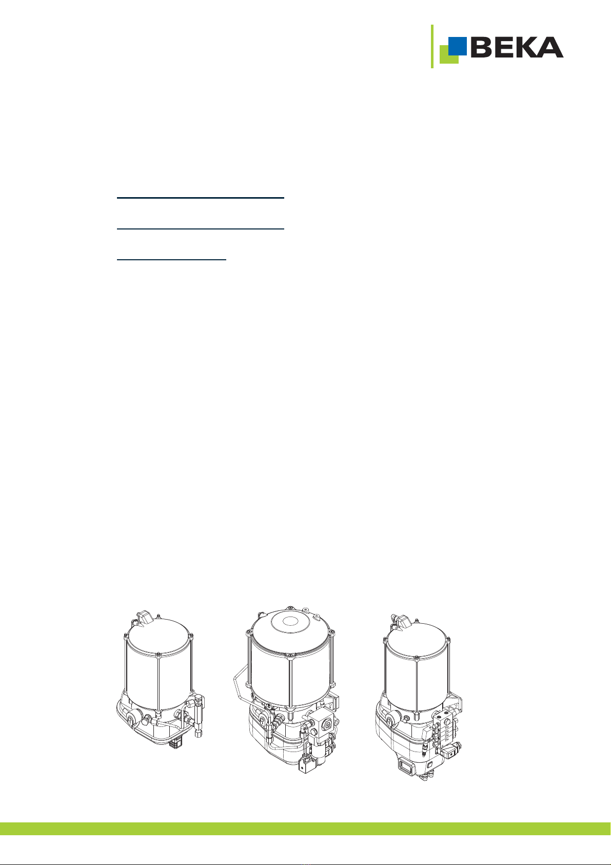
3.2.1 Central lubrication pump FKGGM - EP . . . . . . . . . . . . . . . . . . . . . . . . . . . . . . . . . . . . . . . . . . . . . 13
3.2.2 Central lubrication pump FKGGM - EPR . . . . . . . . . . . . . . . . . . . . . . . . . . . . . . . . . . . . . . . . . . . . 14
3.2.3 Central lubrication pump FKGGM - EP / EPR with installed MX-F distributor . . . . . . . . . . . . . . . . 15
3.3 Pump element (PE) . . . . . . . . . . . . . . . . . . . . . . . . . . . . . . . . . . . . . . . . . . . . . . . . . . . . . . . . . . . . . . . . . 16-17
3.3.1 Pump elements PE-60, PE-120 und PE.170 . . . . . . . . . . . . . . . . . . . . . . . . . . . . . . . . . . . . . . . . . 17
3.3.2 Pump element PE-120 V . . . . . . . . . . . . . . . . . . . . . . . . . . . . . . . . . . . . . . . . . . . . . . . . . . . . . . . . 18
3.3.3 Pu tral lubrication pumps for single line systems. . . . . . 19-20mp element with solenoid valve at cen
4. . . . . . . . . . . . . . . . . . . . . . . . . . . . . . . . . . . . . . . . . . . . . . . . . . . . . . . . . . . . . . . . . . . . . . 21Installation dimensions
Installation dimensions of construction variation of motor housing. . . . . . . . . . . . . . . . . . . . . . . . . . . . . . . . . . . . . . 21
4.1 Central lubrication pump FKGGM - EP . . . . . . . . . . . . . . . . . . . . . . . . . . . . . . . . . . . . . . . . . . . . . . . . . . . . . . 22
4.1.1 Central lubrication pump FKGGM - EP 1,9 liter reservoir . . . . . . . . . . . . . . . . . . . . . . . . . . . . . . . . 22
4.1.2 Central lubrication pump FKGGM - EP . . . . . . . . . . . . . . . . . . . . . . . . . . . . . . . . . . . . . . . . . . . . . 22
4.1.2.1 2,5 liter reservoir - without level monitoring . . . . . . . . . . . . . . . . . . . . . . . . . . . . . . . . . . . . . . . . . . 22
4.1.2.2 2,5 liter reservoir - with level monitoring . . . . . . . . . . . . . . . . . . . . . . . . . . . . . . . . . . . . . . . . . . . . . 23
4.1.2.3 2,5 liter reservoir - with filling cover. . . . . . . . . . . . . . . . . . . . . . . . . . . . . . . . . . . . . . . . . . . . . . . . . 23
4.1.3 Central lubrication pump FKGGM - EP 4 liter reservoir . . . . . . . . . . . . . . . . . . . . . . . . . . . . . . . . . 24
4.1.4 Central lubrication pump FKGGM - EP 8 liter reservoir . . . . . . . . . . . . . . . . . . . . . . . . . . . . . . . . . 24
4.1.5 Central lubrication pump FKGGM - EP 12 liter reservoir . . . . . . . . . . . . . . . . . . . . . . . . . . . . . . . . 25
4.1.6 Central lubrication pump FKGGM - EP 16 liter reservoir . . . . . . . . . . . . . . . . . . . . . . . . . . . . . . . . 26
4.1.7 Central lubrication pump FKGGM - EP 20 liter reservoir . . . . . . . . . . . . . . . . . . . . . . . . . . . . . . . . 27
4.1.8 Central lubrication pump FKGGM - EP 30 liter reservoir . . . . . . . . . . . . . . . . . . . . . . . . . . . . . . . . 28
4.2 Central lubrication pump FKGGM - EPR . . . . . . . . . . . . . . . . . . . . . . . . . . . . . . . . . . . . . . . . . . . . . . . . . . . . . 29
4.2.1 Central lubrication pump FKGGM - EPR 4 liter reservoir . . . . . . . . . . . . . . . . . . . . . . . . . . . . . . . . 29
4.2.2 Central lubrication pump FKGGM - EPR 8 liter reservoir . . . . . . . . . . . . . . . . . . . . . . . . . . . . . . . . 29
4.2.3 Central lubrication pump FKGGM - EPR 12 liter reservoir . . . . . . . . . . . . . . . . . . . . . . . . . . . . . . . 30
4.2.4 Central lubrication pump FKGGM - EPR 15 liter reservoir . . . . . . . . . . . . . . . . . . . . . . . . . . . . . . . 31
4.2.5 Central lubrication pump FKGGM - EPR 20 liter reservoir . . . . . . . . . . . . . . . . . . . . . . . . . . . . . . . 32
4.3 Central lubrication pump FKGGM - EP with installed MX-F distributor . . . . . . . . . . . . . . . . . . . . . . . . . . . . . . 33
5. . . . . . . . . . . . . . . . . . . . . . . . . . . . . . . . . . . . . . . . . . . . . . . . . . . . . . . . . . . . . . . . . . . . . . . . . . . . . . . . 34Accessories
5.1 Level monitoring . . . . . . . . . . . . . . . . . . . . . . . . . . . . . . . . . . . . . . . . . . . . . . . . . . . . . . . . . . . . . . . . . . . . . . 34
5.1.1 FKGGM-EP pump - Proximity switch with plug-type connection M12x1 - 10-60 V/DC: . . . . . . . . . 34
5.1.2 FKGGM-EP pump - Proximity switch with plug-type connection M12x1 - 90-250 V/AC. . . . . . . . . 35
5.1.3 FKGGM-EP pump - Proximity switch - connection cubic plug acc. to DIN 43650 . . . . . . . . . . . . . 35
5.1.4 FKGGM-EPR pump - Proximity switch with plug-type connection M12x1 . . . . . . . . . . . . . . . . . . . 36
5.1.5 FKGGM-EPR pump - Ultrasonic sensor with plug-type connection M12x1 . . . . . . . . . . . . . . . . . . 37
5.2 Micro switch at pressure relief valve . . . . . . . . . . . . . . . . . . . . . . . . . . . . . . . . . . . . . . . . . . . . . . . . . . . . . . . 37
2
Subject to alterations!
...a product from
BAL2076_central lubrication pump_0119EN
© BEKA 2019 All rights reserved

Subject to alterations!
...a product from
BAL2076_central lubrication pump_0119EN
© BEKA 2019 All rights reserved
5.3 Control unit . . . . . . . . . . . . . . . . . . . . . . . . . . . . . . . . . . . . . . . . . . . . . . . . . . . . . . . . . . . . . . . . . . . . . . . . . . 38
5.3.1 General . . . . . . . . . . . . . . . . . . . . . . . . . . . . . . . . . . . . . . . . . . . . . . . . . . . . . . . . . . . . . . . . . . . . . . 38
5.3.2 Collective fault signal . . . . . . . . . . . . . . . . . . . . . . . . . . . . . . . . . . . . . . . . . . . . . . . . . . . . . . . . . . . 38
6. Assembly instruction of central lubrication pump . . . . . . . . . . . . . . . . . . . . . . . . . . . . . . . . . . . . . . . . . . . . . . . 39
6.1 Installation position central lubrication pump FKGGM - EP . . . . . . . . . . . . . . . . . . . . . . . . . . . . . . . . . . . . . 39
6.2 Installation position central lubrication pump FKGGM - EPR . . . . . . . . . . . . . . . . . . . . . . . . . . . . . . . . . . . . 39
6.3 Assembly of pipes and hydraulic hoses . . . . . . . . . . . . . . . . . . . . . . . . . . . . . . . . . . . . . . . . . . . . . . . . . . . . 39
7. Start-up . . . . . . . . . . . . . . . . . . . . . . . . . . . . . . . . . . . . . . . . . . . . . . . . . . . . . . . . . . . . . . . . . . . . . . . . . . . . . . . . . . 40
7.1 Connection of the central lubrication pump FKGGM - EP or EPR without control unit . . . . . . . . . . . . . . . . . . 41
7.1.1 12 / 24 V DC with line connection . . . . . . . . . . . . . . . . . . . . . . . . . . . . . . . . . . . . . . . . . . . . . . . . . . 41
7.1.2 12 / 24 V DC with bayonet plug 7 pol., connection line 2-cores . . . . . . . . . . . . . . . . . . . . . . . . . . . 41
7.1.3 12 / 24 V DC with cubic plug. . . . . . . . . . . . . . . . . . . . . . . . . . . . . . . . . . . . . . . . . . . . . . . . . . . . . . 41
7.1.4 100-250 V AC with Hirschmann plug . . . . . . . . . . . . . . . . . . . . . . . . . . . . . . . . . . . . . . . . . . . . . . . 41
7.1.5 100-250 V AC with Harting plug . . . . . . . . . . . . . . . . . . . . . . . . . . . . . . . . . . . . . . . . . . . . . . . . . . . 41
7.2 Connection of the central lubrication pump FKGGM - EP or EPR with control unit. . . . . . . . . . . . . . . . . . . . . 42
7.2.1 Control unit type: EP-tronic . . . . . . . . . . . . . . . . . . . . . . . . . . . . . . . . . . . . . . . . . . . . . . . . . . . . . . 42
7.2.2 Control unit type: EP-tronic with intermediate housing . . . . . . . . . . . . . . . . . . . . . . . . . . . . . . . . . . 43
7.2.3 Control unit type: BEKA-troniX1 . . . . . . . . . . . . . . . . . . . . . . . . . . . . . . . . . . . . . . . . . . . . . . . . . . . 44
7.2.4 Control unit type: BEKA-troniX1 - with intermediate housing . . . . . . . . . . . . . . . . . . . . . . . . . . . . . 45
7.2.5 Control unit type: EP-tronic ZX . . . . . . . . . . . . . . . . . . . . . . . . . . . . . . . . . . . . . . . . . . . . . . . . . . . 46
7.2.6 Control unit type: EP-tronic ZX - with intermediate housing . . . . . . . . . . . . . . . . . . . . . . . . . . . . . . 47
7.2.7 Control unit type: EP-tronic ZX - with intermediate housing and temperature sensor . . . . . . . . . . 48
7.2.8 Control unit type: EP-tronic ZX - S1 - with intermediate housing . . . . . . . . . . . . . . . . . . . . . . . . . . 49
7.2.9 Control unit type: EP-tronic ZX - S2 - with intermediate housing (12/24 V DC) . . . . . . . . . . . . . . . 50
7.2.10 Control unit type: EP-tronic ZX - S2 - with intermediate housing (100-250 V AC) . . . . . . . . . . . . . 51
7.3 Basic filling of central lubrication pump . . . . . . . . . . . . . . . . . . . . . . . . . . . . . . . . . . . . . . . . . . . . . . . . . . . . . 52
7.4 Ventilation of central lubrication pump . . . . . . . . . . . . . . . . . . . . . . . . . . . . . . . . . . . . . . . . . . . . . . . . . . . . . . 52
8. Maintenance . . . . . . . . . . . . . . . . . . . . . . . . . . . . . . . . . . . . . . . . . . . . . . . . . . . . . . . . . . . . . . . . . . . . . . . . . . . . . . 53
8.1 Preventive repair (wear part) . . . . . . . . . . . . . . . . . . . . . . . . . . . . . . . . . . . . . . . . . . . . . . . . . . . . . . . . . . . . 53
8.2 Level of central lubrication pump . . . . . . . . . . . . . . . . . . . . . . . . . . . . . . . . . . . . . . . . . . . . . . . . . . . . . . . . . 54
8.2.1 Central lubrication pump without control unit and without level monitoring . . . . . . . . . . . . . . . . . . 54
8.2.2 Central lubrication pump with level monitoring . . . . . . . . . . . . . . . . . . . . . . . . . . . . . . . . . . . . . . . . 54
8.2.3 Central lubrication pump with control unit . . . . . . . . . . . . . . . . . . . . . . . . . . . . . . . . . . . . . . . . . . . . 54
9. Repair
9.1 Central lubrication pump does not operate . . . . . . . . . . . . . . . . . . . . . . . . . . . . . . . . . . . . . . . . . . . . . . . . . . 55
9.1.1 Central lubrication pump without control unit . . . . . . . . . . . . . . . . . . . . . . . . . . . . . . . . . . . . . . . . . 55
9.1.2 Central lubrication pump with control unit . . . . . . . . . . . . . . . . . . . . . . . . . . . . . . . . . . . . . . . . . . . . 55
9.2 Filling of the central lubrication pump . . . . . . . . . . . . . . . . . . . . . . . . . . . . . . . . . . . . . . . . . . . . . . . . . . . . . . 56
9.2.1 Filling procedure . . . . . . . . . . . . . . . . . . . . . . . . . . . . . . . . . . . . . . . . . . . . . . . . . . . . . . . . . . . . 56-57
9.2.2 Further filling variants of central lubrication pump . . . . . . . . . . . . . . . . . . . . . . . . . . . . . . . . . . . . . 58
9.2.3 Filling connection and filling tools . . . . . . . . . . . . . . . . . . . . . . . . . . . . . . . . . . . . . . . . . . . . . . . . . . 59
9.3 Exchange distributor of a central lubrication pump with installed distributor . . . . . . . . . . . . . . . . . . . . . . . . . 60
9.4 Exchange the proximity switch of a distributor. . . . . . . . . . . . . . . . . . . . . . . . . . . . . . . . . . . . . . . . . . . . . . . . 60
9.5 Exchange the pump element . . . . . . . . . . . . . . . . . . . . . . . . . . . . . . . . . . . . . . . . . . . . . . . . . . . . . . . . . . . . . 61
9.5.1 Exchange pump element of the central lubrication pump FKGGM - EP / EPR . . . . . . . . . . . . . . . 61
9.5.2 Exchange pump element of the central lubrication pump with installed distributor . . . . . . . . . . . . 62
9.6 Level error . . . . . . . . . . . . . . . . . . . . . . . . . . . . . . . . . . . . . . . . . . . . . . . . . . . . . . . . . . . . . . . . . . . . . . . . . . . 63
9.6.1 Central lubrication pump FKGGM - EP. . . . . . . . . . . . . . . . . . . . . . . . . . . . . . . . . . . . . . . . . . . . . . 63
9.6.2 Central lubrication pump FKGGM - EPR . . . . . . . . . . . . . . . . . . . . . . . . . . . . . . . . . . . . . . . . . . . . 64
10. Troubleshooting . . . . . . . . . . . . . . . . . . . . . . . . . . . . . . . . . . . . . . . . . . . . . . . . . . . . . . . . . . . . . . . . . . . . . . . . . . . 65
3

Declaration of incorporation
4
Subject to alterations!
...a product from
BAL2076_central lubrication pump_0119EN
© BEKA 2019 All rights reserved

Subject to alterations!
...a product from
BAL2076_central lubrication pump_0119EN
© BEKA 2019 All rights reserved
5

1. General
These operating instructions contain all information that are necessary for installation and- and assembly
operation of the central lubrication system. It helps you getting familiar with the central lubrication system and its
functions and to operate it in a safe, proper and economical way.
It shall help you to avoid risks, damage and downtimes. Furthermore it increases the reliability and thes
service life of the central lubrication system. Apply the operating instructions according to the national
regulations concerning working safety, accident prevention and environmental predection.
Keep the operating manual always at the place of operation. All people working with the central lubrication
system have to be informed of the contents of this manual, especially of the safety instructions. The operator
of the central lubrication system is responsible for the staff.
1.1 Intended use
The central lubrication system is allowed for .only industrial use
The central lubrication system may only be , if it is integrated or attached anotheroperated to
machine and will be operated together with it. Use only lubricants according to the machine
manufacturer specification.
The central lubrication system may only be used according to the technical data (see chapter
2 „technical data“. Never exceed the indicated values. Never operate the device without
lubricant.
Unauthorized at the central lubrication system are .structural changes not permitted We are not liable for
consequential damages of the machine or injuries of persons.
This also belongs to :an intended use
·Pay attention to all notes in the operat manual.ing
·Carry out all maintenance work.
·Observe relevant instructionsall for the work safety and accident prevention during all life cycles of the central
lubrication system.
·You have to have the required professional education and authorization of your company, to carry out the
necessary works at the central lubrication system.
Another use or a use beyond can not be considered to be an intended use.
1.2 Scope of guarantee
The manufacturer g ional performanceuarantees operat safety, reliability and , only under the following
conditions :and in regards to the intended use
·A out by authorized and qualified staffssembly, installation, connection and maintenance are only carried .
·The customer has to cover hazardous parts (e.g. heated or moving parts).
·The central lubrication system is installed and operated according to the operating- and assembly
instructions.
·The mentioned technical data must not be exceed in any case.ed
·Retrofitting and repair works at the central lubrication system may only be done by BEKA.
Guarantees and warranty for any damage at the central lubrication system caused by
improper lubricant (e.g. wear of piston, piston jamming, blockades, brittled sealings etc.) will
expire.
BEKA will generally not assume guaranty claims for any damage caused by lubricants,
although those have been laboratory tested and released by BEKA, as such damage (e.g. by
over-stored or incorrectly stored lubricants, batch fluctuations, etc.) cannot be verified or
reconstructed later.
Attention!
Attention!
Attention!
6
Subject to alterations!
...a product from
BAL2076_central lubrication pump_0119EN
© BEKA 2019 All rights reserved

1.3 Safety instructions
All persons that are in charge with the assembly, start-up, maintenance and operation of the device must
carefully read these instructions. Furthermore this manual must permanently be available at the site of operation!
Basic notes for setup, operation and maintenance can be found below.
1.3.1 Safety notes
Do not only observe the safety instructions within this main point but also have a look at the special safety
warnings that are implemented in other parts of this documentation.
Warning of electrical voltage.
Safety instructions which in case of non-observance might cause hazards to persons are
marked with the general danger symbol.
This symbol warns of hot surfaces
Warning of suspended loads.
Warning of material damage due to electrostatic discharge! Marks potential risks which may
result in material damage, if not avoided.
This heading is used if the improper or general non-observance of the operating manual,
specified work flow and the like might result in central lubrication system damage.
This term is used to point out particular details
Notes directly attached at the unit, must strictly be followed and held in readable condition!
1.3.2 staffQualification and training of
The staff in charge for operation, maintenance, inspection and assembly has to have the
according qualification for these tasks. Competence, responsibility and supervision of staff
must be clearly defined by the operator. In case the staff does not have the necessary
knowledge it has to be instructed and trained accordingly. The operator is obliged to ensure
that the staff fully understands the contents of this user information.
1.3.3 Hazards in case of non-observance of the safety instructions
Results of non-observance of the safety instructions can be hazards to persons, the
environment and for the Non-observance of the safetycentral lubrication system.
instructions may result in the loss of any liability claims. In detail the non-observance could
entail the following hazards:
·F systemailure of important functions.
·Failure of prescribed methods for maintenance and repair
·Danger to persons by electrical, mechanical and chemical effects
·Danger to the environment by leakage of hazardous substances
Attention!
Note!
7
Subject to alterations!
...a product from
BAL2076_central lubrication pump_0119EN
© BEKA 2019 All rights reserved

1.3.4 Owner‘s / operators‘ obligations
If movable, redating, hot or cold parts of the device bear risks, these parts need to be secured
against contact by the customer. This predection against contact must not be removed.
Any leakages of hazardous substances must be drained in a way that no risks for
persons or the environment arise. Please also observe the data sheets and safety data
sheets of the according manufacturers.
Keep to all legal provisions.
Hazards due to electricity are to be excluded.
Examination of pipes and hoses regarding safe provision, use, proper assembly and function
has to be carried out according to regionally applicable directives. Inspection intervals may
not be exceeded.
Defective pipes or hoses must be replaced immediately and professionally.
Hydraulic hoses and polyamide pipes are subject to a natural aging-process and thus
have to be exchanged in regular intervals according to the manufacturer's specifications.
A safety data sheet of the currently used lubricant must be provided at the device.
Observe the universally valid Ordinance on Hazardous Substances in the latest version.
1.3.5 instructionSafety for maintenance, inspection and assembly
All maintenance, inspection and assembly work may only be carried out by qualified
personnel who is sufficiently informed by thorough reading of the user information.
Generally any work at the central lubrication system may only be carried out at complete
standstill and in pressureless as well as disconnected condition. Furthermore appropriate
personal predective equipment (goggles among others) is necessary. The shutdown
procedure of the central lubrication system as described in the manual must be strictly
followed.
Secure the device against intentional or unintentional recommissioning during maintenance
or repair. All safety and predection arrangements have to be put back in place again
immediately after finishing work.
Environmentally hazardous media must be disposed professionally and in correspondence
to relevant legal provisions Polluted and contaminated surfaces have to be cleaned before.
maintenance. Please wear predective equipment to that purpose. See the lubricant
manufacturers' safety data sheets hereto, respectively the data sheets provided by the
manufacturers of auxiliaries and working materials.
Open light and fire are strictly prohibited due to fire hazard during all maintenance-,
inspection- and repair works.
1.3.6 Unauthorized modification and production of spare parts
Modification, repair and alterations of the device are only accepted after manufacturer
feedback. Original spare parts and authorized accessories from the manufacturer contribute
to safety. The use of other parts can result in the loss of any liabilities for the resulting
consequences. BEKAdoes not assume liability for parts that are retrofit by the operator.
1.3.7 modesInadmissible of operation
The operational safety of the central lubrication system is only guaranteed for appropriate application as
indicated in the operating manual. Never exceed the limit values of the technical data.
8
Subject to alterations!
...a product from
BAL2076_central lubrication pump_0119EN
© BEKA 2019 All rights reserved

1.3.8 Electrostatic discharge
Avoid electrostatic discharge! There are electronic components integrated into the devices
which might be destroyed by electrostatic discharge. Observe the safety precautions against
electrostatic discharge according to DIN EN 61340-5-1/-3. Ensure that the environment
(persons, workplace and packing) is well grounded when handling these devices
1.3.9 General hazard warning - residual risk
All components are designed according to valid regulations of the construction of technical
systems in regards to operational safety and accident prevention. Independently from this
the use can lead to hazards for the user or third parties as well as for other technical facilities.
Therefore the device may only fulfill its intended use in a andtechnically acceptable
faultless condition. This has to happen in adherence of the according safety regulations and
under observance of the operating manual. the device and its attachment partsInspect
regularly damage leakages. Liquidsand check them for possible or could escape under
high pressure leakyfrom pressurized components which become .
1.4 Use of hydraulic hoses
If hydraulic hose lines are installed at the pump, the operator has to observe / ensure the
following:
·Examination of proper assembly and function are to be carried out according to regionally applicable directives.
·Examination of pipes and hoses regarding safe provision, use, proper assembly and function has to be carried
out according to regionally applicable directives.
·Inspection intervals may not be exceeded
·Defective pipes or hoses must be replaced immediately and professionally
·Hydraulic hoses and polyamide pipes are subject to a natural aging-process and thus have to be exchanged in
regular intervals according to the manufacturer's specifications
1.5 Transport and storage
Use a suitable lifting device for the transport.
Do not the central lubrication system or .throw impose it to shocks
Use a suitable lifting central lubrication system for transport.
Store the system at a temperature between -40°C to +70°C.
Observe all valid safety and accident prevention regulations for the transport. Wear suitable
predective adequate distance to suspended loadsequipment if necessary. Keep . The
transport help or the elevating device must have the adequate carrying capacity.
When storing the device pay attention that the storage area is cool and dry in order to avoid corrosion of the
individual parts of the device.
1.6 Shutdown
Relief the central lubrication pump from pressure! Shut down current!
Separation of central lubrication pump from current supply must be done by a professional electrican.
Remove all pipes and hoses from the device and loosen all fastenings for the demounting.
1.7 Disposal
Observe the disposal instructions of the lubricant manufacturer when lubricant is changed!
Lubricants or cloths contaminated with lubricant or similar must be collected in specially
marked receptacles and disposed accordingly Disposal of the central lubrication system.
must be done properly and professionally and according to the national and international
laws and regulations.
Moreover, BEKA central lubrication systems could contain batteries. Professionally and
properly disposed batteries will be recycled. They contain important raw materials.
Note!
9
Subject to alterations!
...a product from
BAL2076_central lubrication pump_0119EN
© BEKA 2019 All rights reserved

2. Technical data FKGGM-EP / EPR
GENERAL:
Reservoir capacity:
Central lubrication pump FKGGM - EP: .....................................................1,9 l / 2,5 l / 4 l / 8 l / 12 l / 16 l / 20 l / 30 l
Central lubrication pump FKGGM - EPR:............................................................................ 4 l / 8 l / 12 l / 15 l / 20 l
Medium:..............................................................................................greases up to consistency class NLGI-cl. 2
Operating temp. range: ..........................-25°C to +60°C (depends on lubricant, up to -40°C possible on demand)
Transport and storage temperature:.............................................................................................- 40°C to + 70°C
Sound pressure level: .............................................................................................................................<70db(A
Level monitoring (optional): ...................................................................................................Min. / Max. / reserve
Installation position:
Central lubrication pump FKGGM - EP: ...................................................................................................vertical
Central lubrication pump FKGGM - EPR: ....................................................................................rotating system
PUMP:
Operating voltage for version DC: .......................................................................................................12/24 V DC
Operating voltage for versionAC ( : .......................................................................... 100-250 VAC
via installed PSU)
Current consumption max.......................................................................................................4A(5A, t < 100 ms)
Fuse: ...................................................................................................................................... 5Adelay (DC)
KFZ
................................................................................................................... 6Aautomatic fuse C (AC/DC)Industry
.................................................................................................................................. 6,3Adelay (AC/DC)Industry
Protection class: ...........................................................................................................................................IP 65
Number of outlets:..........................................................................................................................................1 - 3
Pipe connection:..............................................................................................................................ø 6 / ø 8 / ø 10
Delivery rate:
Pump element PE-60 .................................................................................................................0,06 cm / stroke
3
Pump element PE-120 ...............................................................................................................0,12 cm / stroke
3
Pump element PE-120 V ............................................0,12 cm / stroke can be regulated back to 0,05 cm³ / stroke
3
Pump element PE-170...............................................................................................................0,17 cm³ / stroke
max. operating pressure: ..........................................................................................................................350 bar
Pressure limiting valve set to:........................................................................................................280 bar (+15%)
Sense of rotation of agitator blade (FKGGM - EP / EPR)............................................................counter clockwise
MOTOR:
Drive: ...............................................................................................................................D/C motor 12/24 V DC
Power input: ....................................................................................................................................< 100 W (DC)
.......................................................................................................................................................< 130 VA(AC)
Pump speed:...................................................................................................................................15 turns / min.
CONTROL UNIT:
Operating voltage:.............................................................................................................................10 - 60 V DC
MATERIAL:
Lubrication reservoir: ........................................................................................... plastic,transparent / aluminium
Pump housing:..............................................................................................................................aluminium cast
Motor cover / control unit housing:...............................................................................................................plastic
Pump parts: ..................................................................................................................................steel C4 / 720 h
acc. to BEKAcompany standard corrosivity categoryA............................................................................zinc-nickel coated acc. to DIN 50979
Missing details and technical data can be found on the data sheets and operating manuals of the
manufacturers (on request).
Please always observe this documentation for all works with the central lubrication system!
10
Attention!
Subject to alterations!
...a product from
BAL2076_central lubrication pump_0119EN
© BEKA 2019 All rights reserved

Subject to alterations!
...a product from
BAL2076_central lubrication pump_0119EN
© BEKA 2019 All rights reserved
3. Functional description
3.1 Function and setup of a central lubrication system
Use
Wind power plants, compressors, tool machines, textile machines, print machines, packing machines, presses,
plastic-, wood-, or metal processing machines, etc.
3.1.1 Function and setup of a progressive central lubrication system
The progressive central lubrication system consists of a central lubrication pump, a main distributor and
secondary distributors (related on the system). Progressive means that all lube points are lubricated
successively. Therefore this process to lubricate the lube points can easily be monitored by a pressure relief
valve.
The central lubrication pump supplies lubricant to the main distributor. This one supplies lubricant in the right
relation to the secondary distributors. From here lubricant is delivered to the lube points. In case one lube point
would not receive lubricant from a distributor the system blocks and pressure is build up in the line system (up to
280 bar (+15%)).
Lubricant flows out of the pressure relief valve. This ensures that the system is secured and monitored.
Installation example:
Fig. 1:
Central lubrication pump
Secondary distributor
e.g. MX-F
Lube point
lines
Secondary distributor
e.g. MX-F
Main distributor
e.g. SXE-2
Secondary distributor
e.g. LX-4
11

Subject to alterations!
...a product from
BAL2076_central lubrication pump_0119EN
© BEKA 2019 All rights reserved
3.1.2 Function and setup of a single line central lubricatio system
The single line lubrication system consists of a central lubrication pump and distributors. One of the distributors is
equipped with a pressure gauge and pressure switch for monitoring. It shall be installed at the end of the longest
line in the system.
The lubrication cycles can be controlled either by means of the control of the central lubrication pump or by an
external control unit. The reservoir level is monitored (optional).
During the pump operation lubricant is delivered into the pressure lines until the switch pressure is reached. The
switch pressure can be checked at the pressure gauge. The pressure line has to be relieved by a 2/2 way valve in
order to enable the displacement of lubricant in the distributor. The pressure line is automatically relieved when
the pump is switched off.After the pressure line is relieved, the single line distributor supplies lubricant to the lube
points.
Installation example:
Fig. 2:
Central lubrication
pump
Lines towards the
lube points
Single line distributor
e.g. UEN
Single line distributor
e.g. UEN with pressure switch
12

Level monitoring
Ventilation
Agitator blase
large version
Straight filling connection
Pump housing
with motor
Pump bracket
Filling nipple
Lower motor
housing
Reservoir cover
Level sticker
BEKA WIND
Reservoir 8 liter
WS-fitting
Pressure relief valve
Steel pipe ø6x1
Pump element
PE-170
Pump type platte
Connection
X1
3.2 Function central lubrication pump
3.2.1 Central lubrication pump FKGGM - EP
The central lubrication pump FKGGM-EP is an electric driven grease pump and designed to supply lubricant up
to NLGI cl. 2.
The installation has to be done with reservoir in vertical position. The positively controlled metering piston of the
pump element and the agitator blade ensure a perfect priming. The central lubrication pump has a level
monitoring (optional).
Functional description:
The motor powers the eccentric via a gear. The eccentricity effects a suction and pressure movement of the
supply piston. The integrated non-return valve avoids a return pumping of lubricant into the lubrication line. The
pump element is compulsory controlled by the eccentric, thus a function at low temperatures is ensured. The
delivery rate depends on the installed pump element.
The grease reservoirs are equipped with an agitator in order to ensure smooth priming of the delivery piston. The
medium is by the agitator pushed into the suction chamber; at the same time rising gas bubbles are able to leak.
The skimmer at the agitator enables a visual control of available grease in the transparent reservoir.
Components:
Fig. 3 (example 2076 00326)
13
Subject to alterations!
...a product from
BAL2076_central lubrication pump_0119EN
© BEKA 2019 All rights reserved

3.2.2 Central lubrication pump FKGGM - EPR
The central lubrication pump FKGGM-EPR is an electric driven grease pump and designed to supply lubricants
up to NLGI-cl 2.
The follow-up piston in the reservoir enables an installation in each position, also in rotating parts. The installation
in rotating parts implies that the function of the follow-up piston is supported by the centrifugal force. The
positively controlled metering piston of the pump element and the agitator blade ensure a perfect priming
behaviour. The central lubrication pump has an integrated level monitoring (optional).
Functional description:
Lubricant is pressed through a sieve by a spring loaded follow-up piston into the suction room of the pump
element.Air bubbles are crushed.
The motor powers the eccentric via a gear. The eccentricity effects a suction and pressure movement of the
supply piston. The integrated non-return valve avoids a return pumping of lubricant into the lubrication line. The
pump element is positively controlled by the eccentric, thus a function at low temperatures is ensured. The
delivery rate depends on the installed pump element.
The grease reservoirs are equipped with an agitator (for the FKGGM-EPR only in the area of the pump housing)
in order to ensure smooth priming of the delivery piston. The agitator pushes the medium into the suction
chamber; at the same time rising gas bubbles can escape.
Components:
Fig. 4 (example 2076 00584):
Reservoir
4 liter
Level sticker
BEKA WIND
follow-up piston
spring loaded
WS-
fitting
Steel pipe 6x1
Pressure relief valve
with return line
Pump element
PE-170
Pump type plate
Ventilation
Filling nipple
with dust cap
Overfill predection
0,5 bar
Filling connection
for filling press
Pump housing
with motor
Ventilation
screw
Lower motor
housing
14
Subject to alterations!
...a product from
BAL2076_central lubrication pump_0119EN
© BEKA 2019 All rights reserved

3.2.3 Central lubrication pump FKGGM - EP with installed MX-F distributor
Description corresponds to FKGGM-EP/EPR .
Additionally a distributor is directly installed at the pump.
Distributor MX-F
The progressive distributor MX-F consists of an initial-, middle, and end element and is directly attached to the
pump. The progressive distributor is designed for an operating pressure up to 300 bar. Due to the progressive
piston control of the distributor, a high operational safety is ensured.
Monitoring the distributor:
The progressive distributor MX-F can easily be monitored by means of a proximity switch due to ist hydraulic
piston control. The pistons are moved by incoming lubricant so that the metered lubricant flows out of the outlets
inevitably and at one outlet after the other. The proximity switch monitors the piston movement. The proximity
switch sends a signal to the control unit at each piston movement. If the signal is not send within an indicated
monitoring time, the connected control unit sends an error message.
Components:
Fig. 5 (example 2076 00118): Ventilation
Reservoir
2,5 liter
Level label
BEKA WIND
Filling nipple with
dust cap
Pump housing
Type plate of pump
Connection
Distributor combination
MXF 5/5
Pump element
PE-170
Greaser with
dust cap
Straight filling
connection
Motor housing
top with motor
Motor housing
bottom
Components FKGGM-EPR:
Fig. 6 (example 2076 00599):
Ventilation
Distributor combination
MXF 4/3
Overfill protection
Pump element
PE-170
Straight filling
connection
Motor housing
top with motor
Motor housing
bottom
level label
BEKA WIND
Reservoir 4 Liter
Filling nipple with
dust cap
Level switch
Pump housing
Ventilation screw
Type plate of pump
Connection
15
Subject to alterations!
...a product from
BAL2076_central lubrication pump_0119EN
© BEKA 2019 All rights reserved

Subject to alterations!
...a product from
BAL2076_central lubrication pump_0119EN
© BEKA 2019 All rights reserved
3.3 Pump element (PE)
The pump element supplies the lube points with lubricant or forward the output rate to the distributor.
Functional description:
The actuation of the supply piston is enforced via the piston eccentric ring. During the suction process the supply
piston is moved into a final position. The metering chamber is filled with lubricant and another turing movement of
the eccentric ring effects that the supply piston closes the suction drilling whereby lubricant is supplied towards
the outlet via the non-return valve.
The pressure line shall only be connected if the pump element supplies air free. The non-return valve avoids that
lubricant is drawn back. Supplied lubricant always has to be clean to ensure the function of the non-return valve.
The pump elements can be ordered with or without pressure limiting valves. The installed pressure limiting valve
predects the system from overload.
Fig. 7:
Pump element supplies:
Pump element draws:
Supply piston
Non-return valve
Piston eccentric ring
Intake bore hole
Lubricant
16

There are pump elements with different delivery rates that can be installed in the lubrication pumps FKGGM-EP
and FKGGM-EPR.
The pump elements can be delivered with pressure connection ø6, ø8 or ø10 (optional with pressure limiting
valve). The use of a pressure limiting valve is recommended, optional also a pressure limiting valve with micro
switch is available.
Fig. 8:
Technical data:
Delivery rate PE-60:..........................................................................................................................0,06 / stroke
3
Delivery rate PE-120: ..................................................................................................................0,12 cm / stroke
3
Delivery rate PE-170:..................................................................................................................0,17 cm³ / stroke
..................................................................................................................................................................................(all types not adjustable)
Operating pressure: .........................................................................................................................max. 350 bar
Pressure limiting valve:........................................................................................................set to 280 bar (+15%)
Lubricant:...................................................................................................greases NLGI-cl. 00/000 to NLGI-cl. 2
Pressure limiting valve:...................................................................................................................with or without
Pipe
connection ø6
ca. 55
ca. 90
M20x1,5
Pressure limiting valve
set to 280 bar (+15%)
AF 17
AF 19
AF 17
AF 24
AF 19
M14x1,5
Ø 8
Reduction fitting
pipe Ø 6 - Ø 8
AF 17
AF 17
AF 19
ca. 51
Reduction fitting
pipe Ø 6 - Ø 10
AF 17
AF 14
AF 19
Ø 6
Ø 10
ca. 41
3.3.1 Pump elements PE-60, PE-120 and PE-170
(all with fix delivery rate)
Fig. 9: (Example PE-120)
Pressure limiting valve
with micro switch
17
Subject to alterations!
...a product from
BAL2076_central lubrication pump_0119EN
© BEKA 2019 All rights reserved

3.3.2 Pump element PE-120 V
The pump element PE-120 V with controllable output rate is set to full lift by default.
Fig.10:
Regulation of metering volume:
·Remove the sealing screw (fig. 10, pos. 1) by means of a hexagon socket wrenchAf5
·Supply rate is adjusted by means of a screw driver at the adjusting disc (Fig. 10, Pos. 2).
·Turn clockwise to reduce the output rate.
·Turn counterclockwise to increase output rate.
·Maximum stroke of adjusting = 2,4 mm = 6 notches
·1 turn of the adjusting disc = 0,8 mm = 2 notches
·Tighten screw plug (Fig. 10, Pos. 1) including sealing ring
Technical data:
Delivery rate PE-120 V:................................................................................................................0,12 cm / stroke
3
Regulation:............................................................................................................possible min. 0,05 cm³ / stroke
..............................................................................................................................................6 notches per / turn
1
2
...............................................................................................................................reduction 0,013 cm³ per notch
Operating pressure: .........................................................................................................................max. 350 bar
Pressure limiting valve:....................................................................................................................set to 280 bar
Lubricant:.............................................................................................grease up to NLGI-cl. 00/000 to NLGI-cl. 2
Pressure limiting valve:...................................................................................................................with or without
Fig.11:
1
2
1
2
13,0
0,12
0,11
0,10
0,09
0,08
0,07
0,06
0,05
0,04
0,03
0,02
0,01
0
2,0 2,5
Delivery rate (cm³) / stroke
00,5 1,5
135
24
0Notches
Turns
6
18
Subject to alterations!
...a product from
BAL2076_central lubrication pump_0119EN
© BEKA 2019 All rights reserved

Subject to alterations!
...a product from
BAL2076_central lubrication pump_0119EN
© BEKA 2019 All rights reserved
3.3.3 Pu tral lubrication pumps for single line systemsmp element with solenoid valve at cen
The solenoid valve which is installed at the central lubrication pump is a 2/2-way valve, consisting of valve part,
connection block and pump element (fig. 12).
As soon as the switching pressure, as adjusted, is reached, the central lubrication pump is switched off and the
solenoid valve releases the way to the reservoir return. The main line is relieved and lubricant is supplied to the
lube points by the distributor.
Fig. 12 :
Technical data:
Way seat valve: VP1-S-A24
Type of actuation: 24V DC electric
Switch symbol: S
Connection: 1/4"
Volume flow: Q 15 l / min
max.
Operating pressure: p 400 bar
max.
Central plug
Nominal power: 20 P (W)
N
Current: 0,83 l (A)
N
Manual emergency button
Press the button
max. actuation pressure 80 N
1) this dimensions depends on the
manufacturing process and can have
up to 40 mm acc. to EN 175 301-803
A
2)
adapter can be installed offset 22,5°
or 180°,
at adjacent order not all angle
positions are possible
switch symbol
Adapter )
2
Cable fitting
Solenoid valve
Pump element
Connection block
19

Subject to alterations!
...a product from
BAL2076_central lubrication pump_0119EN
© BEKA 2019 All rights reserved
Contact
box for
connection
at intermediate
housing
Oil flex line 110
3G x 1 with PE
Plug for
solenoid valve
24 V/DC
K1291_1
The cable with two sided plug for the connection of the solenoid valve is already installed at the pump
housing.
Connection solenoid valve via the intermediate housing:
Fig. 13:
Connection of solenoid valve via flange socket M12 at housing:
Fig. 14:
Round plug
M12
angled
Oil flex line 110
2 x 1 without PE
Plug for
solenoid valve
K1370
24 V/DC
Flange socket M12
20
This manual suits for next models
4
Table of contents
Other BEKA Lubrication System manuals
Popular Lubrication System manuals by other brands

Emerson
Emerson NL4-LBM Series RE-ASSEMBLY INSTRUCTIONS

DROPSA
DROPSA Vip4chain User and maintenance manual

Perma
Perma STAR VARIO operating instructions

DROPSA
DROPSA VIP4 Tools Operating and maintenance manual

Lincoln
Lincoln Cobra 501 owner's manual

Wilkerson
Wilkerson L08 Installation and maintenance sheet