manuals.online logo
Brands
  1. Home
  2. •
  3. Brands
  4. •
  5. Bijur Delimon
  6. •
  7. Lubrication System
  8. •
  9. Bijur Delimon SureFire II Instruction manual

Bijur Delimon SureFire II Instruction manual

BIJUR DELIMON INTERNATIONAL
TEL (+44) 01432 365000
WWW.BIJURDELIMON.COM
WWW.BDICOOLING.COM
Denco Lubrication Ltd,
Ramsden Court, Ramsden Road,
Rotherwas Industrial Estate,
Hereford, Herefordshire, HR2 6LR
71070 • R3 11/161.
SureFire II Lubricator
Single Phase - Quick Start Manual
PDI Operation
The SureFire II PDI Lubricator has a motor-driven pump that
pulls lubricant in from the reservoir and delivers pressurised
lubricant to the distribution network through the outlet(s) in
the top plate. Pressurising the distribution network forces all of
the positive displacement injectors (PDIs) in the system to fire,
discharging the lubricant that was stored in each of their
discharge chambers during the last pump cycle.
The pressure in the main line continues to rise activating the
pressure switch until relief pressure is reached, at which stage,
the relief valve opens and discharges the pressurised lubricant
back into the reservoir. The pressure switch can be used to stop
the motor, and momentary pressure in the main line becomes
greater than the pressure at the outlet side of the gear pump.
This pressure differential actuates a quick dump valve which
relieves the main line pressure back into the reservoir.
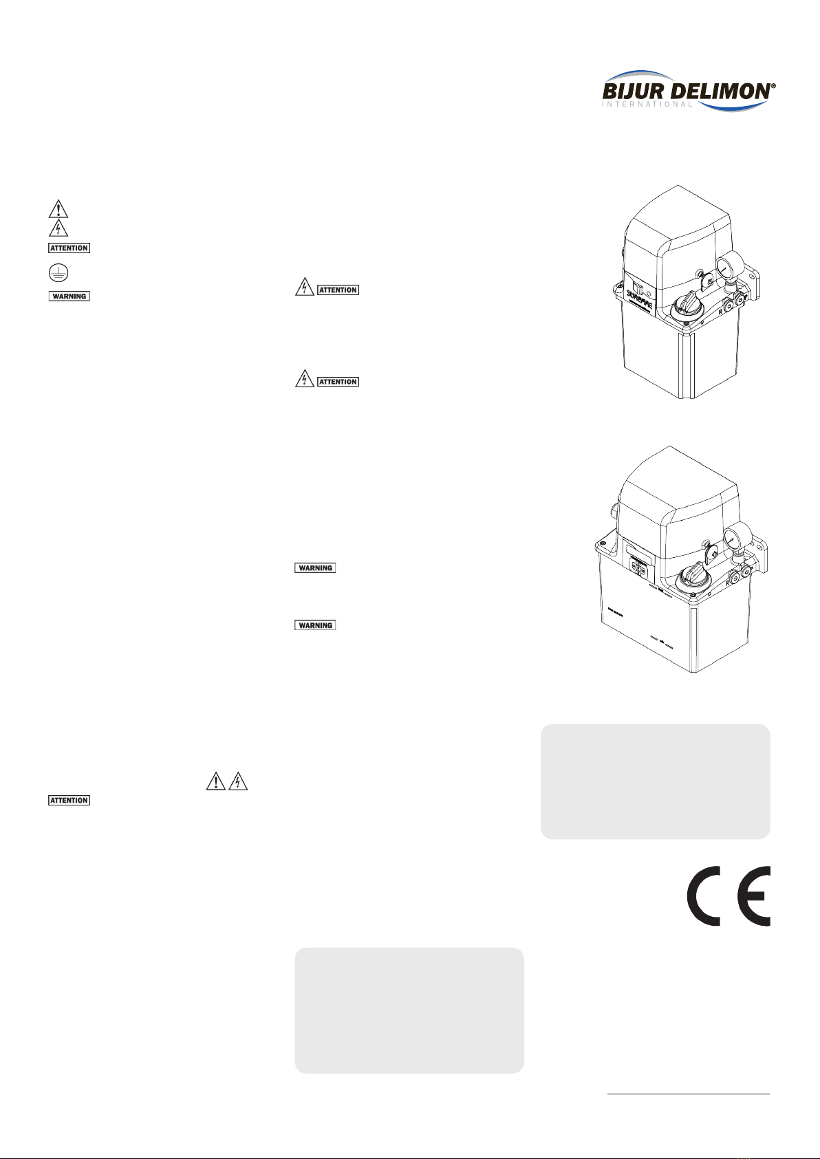
2 Litre Single Phase Standard
Safety
General safety instructions
Electrical safety instructions
Safety instructions which promote safe operation
of the lubricator
Safety instructions which promote safe operation of the
lubricator
Conditions and actions that pose potential hazards
to the user are marked by this sign.
All safety and/or warning labels affixed to the SureFire II
lubricator must be maintained in a completely legible condition.
Also, any modifications made to the SureFire II Lubricator (or
to any of its components) must be approved by Bijur Delimon.
prior to its use, otherwise the warranty and any liability by Bijur
Delimon will be null and void.
SLR Operation
The SureFire II SLR Lubricator has a motor-driven pump that
pulls oil in from the reservoir and delivers pressurised oil to the
distribution network through the outlet(s) in the top plate.
Pressurising the distribution network forces all of the
resistance fittings in the system to discharge the oil in
proportioned quantities to the friction points. The resistance
fittings continue to flow and the pump builds pressure until
pressure relief valve setting is reached (75 psi/5 bar). Once the
motor is shut off, pressure in the distribution network returns
to near 0 psi via a quick dump valve.
Installation & Commissioning
Install the SureFire II Lubricator in the
horizontal position ONLY. Attach the lubricator in the desired
location and to the desired equipment by means of an
appropriately sized bolt through each of the (2) mounting holes
in the top plate. (2L&3L=M6, 6L=M8)The lubricator should be
installed in a location that is easy to access, for purposes of
viewing the front panels, for ease of reservoir-filling, for ease
of service and for ease of attachment to the distribution
network plumbing.
Remember the SureFire II lubricator allows attachment of
distribution plumbing to either (or both) sides of the top plate.
If only one side is used, be sure to plug the unused outlet with a
G1/4 BSPP plug (two plugs are included with each lubricator).
Two liquid tight fittings are supplied with the lubricator. Use the
liquid tight fittings to secure the electrical wiring for the
lubricator and to prevent ingress of fluids or dirt into the
motor compartment. Typically one of the fittings is used to
bring “power” into the motor compartment and the other fitting
is used to bring “signal” into or out of the motor compartment.
All tubing, flexible hoses and fittings must be compatible with
the lubricant, operating pressure and surrounding
environment. In general, try to install the lubricator in the
lowest position (vertically) with relation to the rest of the
distribution network and do not allow the tubing to rise and fall
when avoiding obstacles. This is in case air enters the
distribution lines, the bubbles will tend to rise towards the end
of the distribution lines and not get caught anywhere along the
way. Any air bubbles trapped in the distribution network
plumbing may prevent the PDI injectors from working properly.
All electrical connections are to be made by
a qualified technician and all local electrical codes are to be
followed. When electrical connections are being made, do so
before the power leads are connected and before the power is
supplied.
Consult the wiring diagram (located under the motor cover) for
the correct wiring for your SureFire II lubricator.
The installation should include a means of
disconnecting the power supply for servicing. Such means shall
allow for switching off the power during normal operation and/
or in an emergency. Also, a residual current device is required
to automatically disconnect the power supply in the event of a
failure in basic insulation.
This emergency disconnecting switch shall be located in close
proximity to the equipment and be within easy reach. The switch
should be marked as the disconnecting device of the equipment,
shall have ON/OFF positions clearly identified and should meet
the requirements of IEC60947-1 or IEC60947-3.
Be sure that all plumbing distribution lines are clean, are not
kinked and are free from any chips or any other impurities.
Fill the reservoir through the fill cap and/or fill
cap strainer with clean lubricant specified by the Original
Equipment Manufacturer and that meets all of the lubricant
specifications to the right.
Do not overfill the reservoir. Never fill past the
“MAX” level as noted on the reservoir. Overfilling could cause
damage to the electrical components located under the motor
cover.
Pump Priming
Filling the reservoir and turning on the lubricator is usually
enough to prime the pump. However, in the case of a very thick
lubricant, sometimes it’s necessary to assist priming the pump.
Upon initial startup, if no lubricant is being delivered to the
pump outlet, make sure the pump is primed.
Avoid all kinds of impurities as dirt particles are the most
common cause of gear pump failure. If you wish to determine
whether the lubricant you plan on using is approved for use with
Bijur Lubricating Systems, you can consult the Customer
Service Department.
To prime the distribution network, plumb the entire system
(mainline tubing, manifolds, junctions, air/oil blocks, injectors,
injector outlet tubing to bearing points, meter units etc.). Then,
remove a plug or injector at the point furthest away from the
pump. Now, run the pump until bubble-free lubricant flows from
this point. Replace the plug or last injector.
Motor Duty Cycle:
100/115VAC & 200/230VAC motors: S3, 20%, 15 Min.
This means that the maximum continuous “on time” for
any cycle is 3 minutes, and if the motor continuous “on
time” for a cycle is X, the required minimum “off time”
for that same cycle is at least 4X. Each motor has an
internal high temperature cutoff switch.
24VDC motor: S1, Continuous Duty
3 Litre Single Phase w/ Controller
Lubrication Specifications:
Standard Oil version:
20 to 1500 cSt @ operating temperature
Light Oil version:
5-40 cSt @ operating temperature
Grease version(PDI only):
NLGI grade 000 - 00 (40,000 cSt max)
Motor Cover
Motor Assy
Pressure Switch
Pressure Gauge
Oil Pressure Port
1/4 BSPP
Oil Return Port
1/4 BSPP
Filler Cap
Level Switch
Gear Pump
Reservoir Assy
Reservoir Assy
Motor On Led
Momentary Switch
Terminal Strip
Cable Gland
Controller Assy
System Dump Valve
System Relief
Valve
Component Illustration
SureFire II Reservoir Size: 2 Litre 3 Litre 6 Litre 12 Litre
Part Description Part # Part # Part # Part #
24VDC Motor Kit (includes driveshaft + Coupling) 71111-2 71111-6 71111-12
115VAC Motor Kit (includes driveshaft + Coupling) 71112-2 71112-6 71112-12
230VAC Motor Kit (includes driveshaft + Coupling) 71113-2 71113-6 71113-12
Reservoir Kit PLASTIC (gasket included) 71114 71115 71116 N/A
Reservoir Kit METAL (gasket included) 71064 71066 71068 71135
Motor Cover Kit 71117 71118 71118 71118
Pressure Switch Kit PDI Pump 71119
Pressure Switch Kit SLR Pump 71120
Filler Cap Kit (with Inlet Filter Unit) 71121
Terminal Strip Kit 71122
Controller Kit - TIMER 71123-T
Controller Kit - LITE Controller 71123-L
Controller Kit - PREMIUM Controller 71123-P
Membrane Switch/Label Kit for Timer/Controllers 71029
Level Switch Kit (Standard Oil Option) 71124-2 71124-6 71124-12
Momentary Switch Kit 71125
Motor on LED 115VAC / 230VAC 71126
Motor on LED 24VDC 71127
Gear Pump Kit 71128
Pressure Gauge (PDI) 71129
Pressure Gauge (SLR) 71130
Dump Valve Kit 71131
Relief Valve Kit (PDI) 71132
Relief Valve Kit (SLR) 71133
Cable Gland Kit 71134
SureFire II Spare Parts
Maintenance and Service
The SureFire II lubricator does not require much
maintenance. After initial set-up, the lubricator
requires only the following maintenance:
a) When filling the reservoir with oil, the lubricant
must be poured through the oil-filler screen
b) The oil-filler screen must be inspected after
every 4 or 5 fillings and cleaned if necessary
c) If filling with a fluid grease, due to the fact that
SureFire II PDI fluid grease models omit the
filter screens, be sure the grease is fresh, clean,
and is not higher than 40,000 cSt viscosity.
d) Do not use aggressive cleaners to clean the
lubricator. Use only mild cleaners or degreasers
to clean the lubricator.
In the event of having to replace a
pressure gauge, appropriate pipe thread sealant
applied to the male thread of the new gauge is
recommended.
BIJUR DELIMON INTERNATIONAL
TEL (+44) 01432 365000
WWW.BIJURDELIMON.COM
WWW.BDICOOLING.COM
Denco Lubrication Ltd,
Ramsden Court, Ramsden Road,
Rotherwas Industrial Estate,
Hereford, Herefordshire, HR2 6LR
71070 • R3 11/163.
SureFire II Lubricator
Single Phase - Quick Start Manual
Dimensional Schematics
SureFire II 2, 3, 6 & 12 Litre (115 VAC, 230 VAC and 24 VDC Single Phase)
Measurements shown in millimeters.
2 Litre 3 Litre
5
5
188
153
7
(184)
5
5
233
215
7
182.50
6 Litre 12 Litre
5
5
261
225
9
243.50
40
332
252
7
176
9 (x4)
Troubleshooting
Pre-mature wear of the gear pump and the other moving parts is usually caused by dirty or contaminated
lubricant.
Failure of the PDI injectors or SLR Meter Units to deliver lubricant can be caused by an incorrect commissioning
sequence, resulting in either air or dirt being trapped in the distribution network.
BIJUR DELIMON INTERNATIONAL
TEL (+44) 01432 365000
WWW.BIJURDELIMON.COM
WWW.BDICOOLING.COM
Denco Lubrication Ltd,
Ramsden Court, Ramsden Road,
Rotherwas Industrial Estate,
Hereford, Herefordshire, HR2 6LR
71070 • R3 11/164.
SureFire II Lubricator
Single Phase - Quick Start Manual
24VDC Wiring Diagrams
Surefire II Technical Specifications
Output Volume – 115 VAC, 230 VAC (max.)
Single Phase:
250cc/min @ 60 Hz
210cc/min @ 50 Hz
Output Volume – 24 VDC (max.) :
250cc/min
Output Pressure (max.):
PDI: 450 psi (31 bar)
SLR: 75 psi ( 5 bar)
Motor Voltage Options:
100/115 VAC 50/60 Hz Single Phase
200/230 VAC 50/60 Hz Single Phase
24 VDC
Motor Power Requirements:
100/115 VAC Single Phase: 1.0 amps
200/230 VAC Single Phase: 0.70 amps
24VDC: 2.4 amps
Motor Duty Cycle:
100/115VAC and 200/230VAC: S3, 20%,15
Min. This means that the maximum continuous
“on time” for any cycle is 3 minutes, and if the
motor continuous “on time” for a cycle is X, the
required minimum “off time” for that same
cycle is at least 4X. Each motor has internal
high temperature cutoff switch.
24VDC motor: S1, Continuous Duty
Operating Temperature Range:
40°F through 105°F (5°C through 40°C)
IP Enclosure Rating:
IP-54
Electrical Fitting:
Liquid tight cable gland
Output Connection (x2, one each side):
G 1/4 BSPP
Return Line Connection:
G 1/4 BSPP
Reservoir Fill Screen (oil only):
40 mesh, removable
Single (main) Feed Line:
6mm O.D. minimum recommended
Reservoir Volume:
2, 3, 6 & 12 Liter
Reservoir Material:
Luran (Blue Tint) for 2, 3 and 6 litre
Steel for 2, 3, 6 and 12.0 litre
24VDC PDI TERM BLOCK
24VDC PDI TIMER
24VDC PDI CONTROLLER
Wire Sizes - Terminal Block
Contact Description Wire Type Size Strip Length
All All User Terminals
(Quick Connection)
Solid Wire /
Stranded Wire
20 - 14 AWG
(0.52 - 2.1mm2)
7.5 - 8.5 mm
Wire Sizes - Controller/Lite Controller/Timer
Contact Description Wire Type Size Strip Length
J1 & J2 Power Input
(Quick Connection)
Solid Wire /
Stranded Wire
24-14 AWG
(0.2 – 2.08mm2)9-10 mm
J11 & J12 Fault Contact
(Screw Connection)
Solid Wire /
Stranded Wire
24-16 AWG
(0.2 – 1.5mm2)5-6 mm
J10 All other inputs
(Quick Connection)
Solid Wire /
Stranded Wire
26-20 AWG
(0.13 – 0.52mm2)9-10 mm
Motor Cover
Note:
All wiring diagrams are located on the inside
of the motor cover of Surefire II.
Refer to the following documents:
+ Data sheet #36410: Surefire II
Wire Strip
Length
8.5
7.5
Wire Size 20-14 AWG
(0.52-2.1mmS

Other Bijur Delimon Lubrication System manuals

Bijur Delimon V5 User manual

Bijur Delimon

Bijur Delimon V5 User manual

Bijur Delimon SureFire II Instruction manual

Bijur Delimon

Bijur Delimon SureFire II Instruction manual

Bijur Delimon TM-5 User manual

Bijur Delimon

Bijur Delimon TM-5 User manual

Bijur Delimon HAP-P User manual

Bijur Delimon

Bijur Delimon HAP-P User manual

Bijur Delimon SureFire II Instruction manual

Bijur Delimon

Bijur Delimon SureFire II Instruction manual

Bijur Delimon CSK User manual

Bijur Delimon

Bijur Delimon CSK User manual

Bijur Delimon TMD-5 User manual

Bijur Delimon

Bijur Delimon TMD-5 User manual

Bijur Delimon SureFire II Instruction manual

Bijur Delimon

Bijur Delimon SureFire II Instruction manual

Bijur Delimon L2P User manual

Bijur Delimon

Bijur Delimon L2P User manual

Bijur Delimon V5 60444 Instruction manual

Bijur Delimon

Bijur Delimon V5 60444 Instruction manual

Bijur Delimon M2500G User manual

Bijur Delimon

Bijur Delimon M2500G User manual

Bijur Delimon V5B User manual

Bijur Delimon

Bijur Delimon V5B User manual

Bijur Delimon MultiPort User manual

Bijur Delimon

Bijur Delimon MultiPort User manual

Bijur Delimon V5 User manual

Bijur Delimon

Bijur Delimon V5 User manual

Bijur Delimon SG-A User manual

Bijur Delimon

Bijur Delimon SG-A User manual

Bijur Delimon WS-E User manual

Bijur Delimon

Bijur Delimon WS-E User manual

Bijur Delimon HAP-P User manual

Bijur Delimon

Bijur Delimon HAP-P User manual

Bijur Delimon Farval CS1000 Manual

Bijur Delimon

Bijur Delimon Farval CS1000 Manual

Bijur Delimon L18P User manual

Bijur Delimon

Bijur Delimon L18P User manual

Bijur Delimon V5B User manual

Bijur Delimon

Bijur Delimon V5B User manual

Bijur Delimon V3 User manual

Bijur Delimon

Bijur Delimon V3 User manual

Popular Lubrication System manuals by other brands

SAFEMATIC IF-103 User interface description

SAFEMATIC

SAFEMATIC IF-103 User interface description

Lincoln SKF CLK Installation and operation manual

Lincoln

Lincoln SKF CLK Installation and operation manual

Perma ULTRA quick start guide

Perma

Perma ULTRA quick start guide

Alemite 3942-B Service guide

Alemite

Alemite 3942-B Service guide

Lincoln B Series manual

Lincoln

Lincoln B Series manual

Perma STAR VARIO operating instructions

Perma

Perma STAR VARIO operating instructions

Pulsarlube MI60 user manual

Pulsarlube

Pulsarlube MI60 user manual

Gruetzner Lubricus V user manual

Gruetzner

Gruetzner Lubricus V user manual

Lincoln QUICKDATA 233 owner's manual

Lincoln

Lincoln QUICKDATA 233 owner's manual

SMC Networks AL Series manual

SMC Networks

SMC Networks AL Series manual

MIRCONA MINIBOOSTER instructions

MIRCONA

MIRCONA MINIBOOSTER instructions

Alemlube EL SERIES Owner technical manual

Alemlube

Alemlube EL SERIES Owner technical manual

Viper Mid MKII Assembly & operation manual

Viper

Viper Mid MKII Assembly & operation manual

Atlas Copco BLG 10 Operator instructions

Atlas Copco

Atlas Copco BLG 10 Operator instructions

Whitmore LUBRICURVE ELECTRO 15 Installation & maintenance manual

Whitmore

Whitmore LUBRICURVE ELECTRO 15 Installation & maintenance manual

Graco GREASE JOCKEY instructions

Graco

Graco GREASE JOCKEY instructions

First Power Stinger Hornet Operator's manual

First Power

First Power Stinger Hornet Operator's manual

Aventics AS1 operating instructions

Aventics

Aventics AS1 operating instructions

manuals.online logo
manuals.online logoBrands
  • About & Mission
  • Contact us
  • Privacy Policy
  • Terms and Conditions

Copyright 2025 Manuals.Online. All Rights Reserved.