5
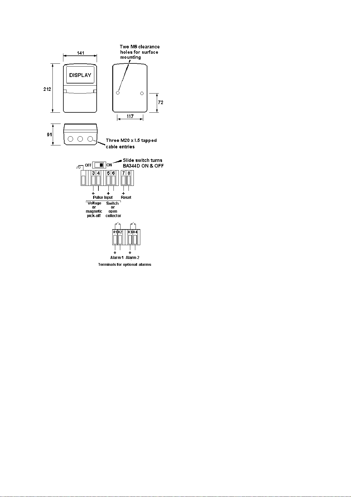
3.3 Pulse input terminals
The BA344D rate totaliser has two alternative
pairs of input terminals enabling the instrument
to count pulses from a wide variety of sources.
Note: Only one pair of input terminals may be
used at one time.
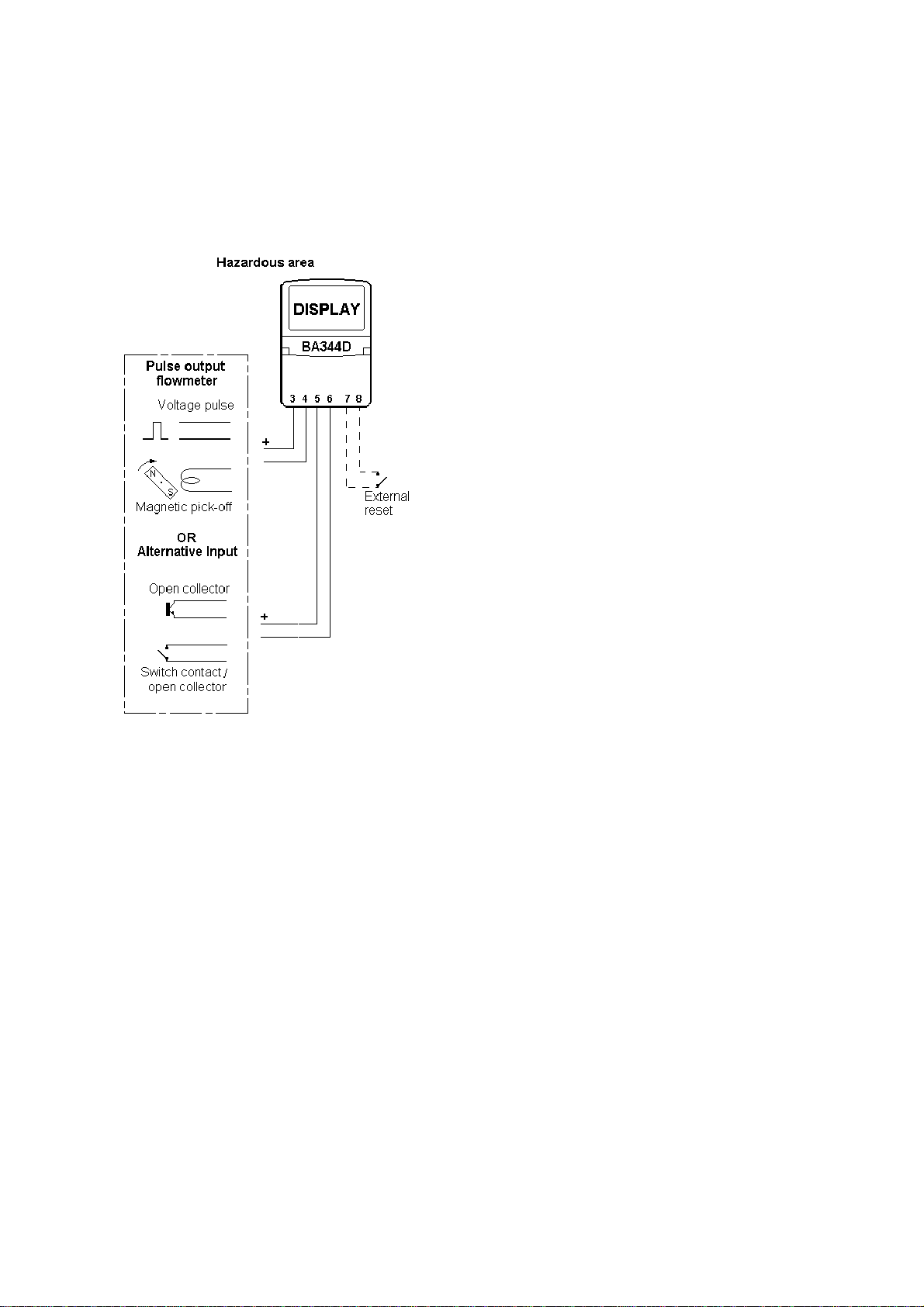
3.3.1 Voltage pulse input
Terminals 3 and 4 are intended for connection
to a voltage pulse source. In Europe, sources
of energy which do not generate more than
1.5V; 100mA and 25mW are, for intrinsic safety
purposes, considered to be simple apparatus
(Clause 5.4 of EN50 020:1994).
Although the BA344D indicator does not itself
comply with the requirements for simple
apparatus, the EC-Type Examination
Certificate specifies that under fault conditions
the voltage, current and power at terminals 3 &
4 will not exceed those specified for simple
apparatus. This allows these input terminals
to be connected to any certified intrinsically
safe apparatus or circuit providing that the
output parameters of the apparatus or circuit
do not exceed: Uo = 28V dc
Io = 100mA dc
Po = 0.7W
The certified intrinsically safe voltage pulse
output of a flowmeter mounted in a hazardous
area, or the output of a certified magnetic pick-
off mounted in a hazardous area may be
directly connected to these terminals providing:
The output parameters of the device do
not exceed the figures shown above.
The device can withstand a 500V rms
insulation test to earth for one minute.
The BA344D EC-Type Examination Certificate
specifies that the maximum equivalent
capacitance and inductance between the two
pulse input terminals 3 and 4 is:
Ci = 30nF
Li = 10µH
To determine the maximum permissible cable
parameters these figures should be subtracted
from the maximum permitted cable parameters
specified for the device connected to terminals
3 and 4.
The BA344D system certificates specify the
maximum permitted cable parameters when a
28V 300ΩZener barrier or galvanic isolator is
connected to these terminals.
3.3.2 Contact or open collector input
Terminals 5 and 6 are intended for connection
to a switch contact or a certified open collector
output. Terminals 5 & 6 output safety
parameters are:
Uo = 3.7V dc
Io = 2mA dc
Po = 2mW
and the maximum permitted external
capacitance and inductance is:
Co = 99µF
Lo = 999mH
Mechanically operated switch contacts comply
with the requirements for simple apparatus.
Providing the switch and the BA344D are both
located in the same hazardous area, the switch
may be connected directly to terminals 5 & 6.
This also applies to most magnetically
operated reed switches used in turbine
flowmeters.
Similarly, certified intrinsically safe open
collector outputs may be directly connected to
terminals 5 and 6
In all cases the device and circuit connected to
terminals 5 & 6 must be capable of
withstanding a 500V rms insulation test to
earth for one minute and have IP20 protection
The maximum input safety parameters for
terminals 5 & 6 are:
Ui = 28V dc
Ii = 100mA dc
Pi = 0.7W
and the equivalent internal capacitance and
inductance are:
Ci = 30nF
Li = 10µH
This allows Zener barriers and galvanic
isolators to be connected to these terminals.
The BA344D system certificates specify the
maximum permitted cable parameters when a
28V 300ΩZener barrier or galvanic isolator is
used to transfer a pulse from the safe area to
the BA344D in a hazardous area.