manuals.online logo
Brands
  1. Home
  2. •
  3. Brands
  4. •
  5. Danfoss
  6. •
  7. Control Unit
  8. •
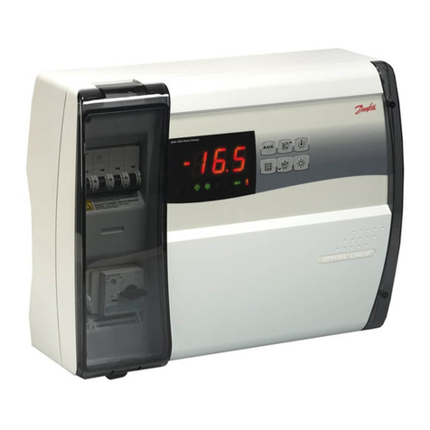
  9. Danfoss PVE 3 Series User manual

Danfoss PVE 3 Series User manual

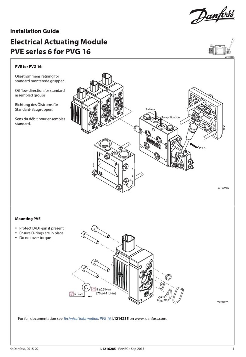
Installation Guide
Electrical Actuating Module
PVE Series 3 for PVG 32
© Danfoss A/S, 2014-03 520L0286 • Rev CB • Mar 2014 1
157R9936
157R9936
Oliestrømmens retning for
standard monterede grupper.
Oil flow direction for standard
assembled groups.
Richtung des Ölstroms für
Standard-Baugruppen.
Sens du débit pour ensembles
standard.
Vbat = Forsyningsspænding/Supply voltage
Versorgungsspannung/Tension d'alimentation
Vs= Signalspænding/Signal voltage
Signalspannung/Tension de commande
E: Nødstop
E: Emergency circuit braker
E: Notschalter
E: Interrupteur
PVEK
PVB
PVP
PVEK-DI
PVS
V310145.A
PVEB
PVEO-R
PVEO
PVEB-DI
max:
P A
Q P B
P A
max:
Q
PVM
[61-79 lbf•in]
7-9 Nm
Proportional aktivering
Proportional activation
Proportionale Betätigung
Commande proportionelle
On/off aktivering
On/off activation
Ein-/Aus-Betätigung
Commande tout ou rien
25 pin SUB-D connector
(MIL-C-24308 /DIN 41652)
Vbat 11 - 15 V / 22 - 30 V
Q :P →A Vs = (0.5 →0.25) ×Vbat+
Q :P →B Vs = (0.5 →0.75) × Vbat+
Neutral Vs = 0,5 ×Vbat+
Vbat 11 - 15 V / 22 - 30 V
Q :P →A Pin 1 (A) Vbat+ Pin 2 (B) 0
Q :P →B 0 Vbat+
Neutral 0 0
2 520L0286 • Rev CB • Mar 2014 © Danfoss A/S, 2014-03
Blokdiagram
Block diagram
Blockdiagramm
Stéreogramme
Retningsindikator
Direction indicator
Richtungsindikator
Indicateur de direction
high
low
Retningssignaler a1, a2
Direction signals a1, a2
Richtungssignale a1, a2
Signaux de direction a1, a2
A-port
0.8 mm ± 0.4 mm
B-port
0.8 mm ± 0.4 mm
Max. belastn. DI-A, DI-B
Max. load DI-A, DI-B
Max. Belastung DI-A, DI-B
Charge maximale DI-A, DI-B
12V / 20 mA 24V / 20 mA
Spænding i neutral
Voltage in neutral
Spannung in Neutralstellung
Tension en position neutre
Minimum: Vbat+ - 1.5 V (high)
Spænding ved udstyring
Voltage on activation
Spannung bei Aussteuerung
Tension en configuration de pilotage
Maximum: 0.2V ( low)
DI-A
DI-B
© Danfoss A/S, 2014-03 520L0286 • Rev CB • Mar 2014 3
Justering af PVE når max. håndtagsvandring overskrides (PVEK/PVEB er forjusteret fra fabrik)
Adjustment of PVE when max. lever travel is exceeded (PVEK/PVEB is factory-preset)
Justierung der PVE wenn max. Hebelwanderung überschritten wird (PVEK/PVEB ist vorjustiert ab Werk)
Ajustage de la PVE quand la course maximale est excédée (est préréglé à l'usine)
Kontroller max. håndtagsvandring i neutralstilling
1. Sæt hydraulisk tryk på systemet
2. Tilslut forsyningsspænding (UDC)
(Signalspænding = 0,5 × UDC), eller afbryd signalspænding (US).
Check max. lever travel in neutral position
3. Make sure the system is supplied with hydraulic power
4. Connect supply voltage (UDC)
(Signal voltage = 0,5 × UDC), or cut off the signal voltage (US).
Max. Hebelwanderung in Neutralstellung kontrollieren:
5. 1Das System unter hydraulischen Druck setzen
6. Versorgungsspannung anschliessen (UDC)
(Signalspannung = 0,5 × UDC), oder die Signalspannung (US).
Contrôler la course maximale du manipulateur en position neutre
7. S'assurer que le circuit hydraulique est fourni d'huile.
Connecter la tension d'alimentation (UDC)
(Tension de commande = 0,5 × UDC),
ou couper la tension de commande (US).
P
T
A
B
max.2[0.08] max.2[0.08]
V310111.A
LS
R
Overskridelse i
Lever travel exceeded in
Überschreitung der Hebelwanderung in
La course maximale est excédée du
PVG 32
Omdrejningsretning for justering af positionstransducer
Direction of rotation for adjustment of position transducer
Drehrichtung beim Justieren des Positionstransducers
Sens de rotation pour l'ajustage du transducteur de position
A-retning
Direction A
A-Richtung
Sense A
A
V310177.A
B-retning
Direction B
B-Richtung
Sense B
V310108.A
B
Transducer omdrejning
Turn of transducer
Transducerdrehung
Rotation du transducteur
Håndtagsbevægelse
Movement of lever
Hebelweg
Mouvement du manipulateur
1⁄4
1⁄2
3⁄4
1.5 mm [0.06 in]
3.0 mm [0.12 in]
4.5 mm [0.18 in]
4 520L0286 • Rev CB • Mar 2014 © Danfoss A/S, 2014-03
Montage af PVE
Installation of PVE
Montage von PVE
Installation de PVE
Udluftning
Hvis gruppen er monteret vertikalt, anbefales det at udlufte ved justerskruer (Pos.A)
Bemærk: Ved PVEK kan det, pga.dens hydrauliske opbygning, være påkrævet at foretage
udluftning.
Bleeding
If the group is installed vertically, it is recommended to bleed it at the adjusting screws
(Pos.A)
Note: Because of the hydraulic build-up of PVEK, it may be necessary to bleed the PVEK.
Entlüftung
Wenn die Gruppe vertikal montiert ist, empfehlen wir an den Justierschrauben zu
entlüften (Pos.A)
Beachte: Wegen des hydraulischen Aufbaus von PVEK kann eine Entlüftung erforderlich
sein.
Purge
Si l'ensemble est monté verticalement, il est recommandé de le purger au
moyen des vis d'ajustage (Pos.A)
Nb! En raison du système hydraulique des PVEKs il peut s'avérer nécessaire de purger.
LS
T P
A
V310109.A
100*[4]
170[6.69]
4
NB:
Pakningen i PVE stikket samt
pakningerne til de enkelte
ledninger, er afgørende for at
korrekt tæthed af stikket opnås.
NB:
The seal in the PVE connector
and the seals for individual
conductors are crucial for
correctly sealing the connector.
NB:
Die Dichtung im PVE-Stecker
sowie die Dichtungen für die
einzelnen Drähte sind für die
Dichtheit des Steckers von
entscheidendem Einfluss.
N.B. :
Le joint de la prise PVE ainsi que
les joints de chaque conducteur,
jouent un rôle essentiel dans la
qualité de l’étanchéité de la prise.
Beskyttelse
Alle PVE-moduler overholder tæthedsgrad IP65 i henhold til
IEC 529. Det anbefales dog, at PVE’en på særligt udsatte steder
beskyttes i form af en afskærmning eller lignende.
Schutzart
Alle PVE-Module erfüllen die Schutzart IP65 gemäß IEC 529.
Es ist jedoch empfehlenswert, der PVE in besonders
ausgesetzten Einsatzbereichen mit einer Abschirmung oder
dergleichen zu schützen.
Protection
All PVE modules comply with protection class IP65 in
accordance with IEC 529.
However, in particularly exposed applications protection in the
form of screening is recommended.
Protection
Tous les modules PVE possèdent le degré de protection IP65
conformément à la IEC 529. Dans les zones particulièrement
exposées, il est cependant conseillé de protéger le PVE à l’aide
d’un écran ou d’un dispositif similaire.
© Danfoss A/S, 2014-03 520L0286 • Rev CB • Mar 2014 5
DI function (black)
Pos. Description Qty. AMP Code No. Code No. Code No.
with
4 m cable
1Wire sealing (blue) 4828904-1 157B4993
min.100 pcs. 157B4995
min. 50 pcs.
2 JPT contact (loose piece) 4 929930-1
3 JPT housing keying A (black) 1 1-967059-1
AMP crimp tool incl. crimp insert for JPT-contact 157B4989
AMP-stik til PVE serie 3
AMP connector for PVE series 3
AMP-Stecker für PVE Serie 3
Kit AMP pour PVE serie 3
Åbning af AMP-stik
Opening of AMP-connector
Öffnen des AMP-Steckers
Ouverture des kit AMP
Kabel med stik
Cable with connector
Kabel mit Stecker
Câble avec connecteur
PVE-funktion (gråt stik)
PVE-function (grey connector)
PVE-Funktion (Grauer Stecker)
PVE-Fonction (Support gris)
Code: 157B4994
(min. 50 pcs.)
DI-funktion (sort stik)
DI-function (black connector)
DI-Funktion (Schwarzer Stecker)
DI-fonction (Support noir)
Code: 157B4995
(min. 50 pcs.)
PVE function (grey)
Pos. Description Qty. AMP Code No. Code No. Code No.
with
4 m cable
1Wire sealing (blue) 4* 828904-1
157B4992
min.100 pcs. 157B4994
min. 50 pcs.
2Blind plug (transparent) 1828922-1
3 JPT contact (loose piece) 4* 929930-1
4 JPT housing keying B (gray) 1 2-967059-1
JPT = AMP Junior Power Timer
Pin 1 Hvid, White, Weiß, Blance
Pin 2 Blå, Blue, Blau, Bleu
Pin 3 Gul, Yellow, Gelb, Jaune
Pin 4 Rød, Red, Rot, Rouge
6 520L0286 • Rev CB • Mar 2014 © Danfoss A/S, 2014-03
Tekniske data
Technical data
Technische Daten
Caractéristiques Techniques
Forsyningsspænding 12 V version 24 V version
Nominel spænding (Vbat): 12 V 24 V
Spændingsområde (Vbat): 11 V - 15 V 22 V - 30 V
Max ripple: 5% 5%
Supply voltage 12 V version 24 V version
Rated voltage (Vbat): 12 V 24 V
Voltage range (Vbat): 11 V - 15 V 22 V - 30 V
Max ripple: 5% 5%
Olieviskositet
Oil viscisity
Ölviskositet
Viscosité de l’huile
Range: 12 - 75 mm2/s [66 - 350 SUS]
Min.: 4 mm2/s [40 SUS]
Max.: 460 mm2/s [2130 SUS]
Filtrering
Filtering
Filtrierung
Filtage
Max. degree of contamination
(ISO 4406): 19/16
Omgivelsestemperatur
Umgebungstemperatur
Température ambiante
Min.: -30°C
Max.: 60°C
Versorgungsspannung 12 V version 24 V version
Nennspannung (Vbat): 12 V 24 V
Spannungsbereich (Vbat): 11 V - 15 V 22 V - 30 V
Max. Klirrfaktor: 5% 5%
Tension d’alimentation 12 V version 24 V version
Tension nominale (Vbat): 12 V 24 V
Plage de tension (Vbat): 11 V - 15 V 22 V - 30 V
Ondulation résiduelle max. 5% 5%
Pilottryk (over tanktryk)
Pilot pressure (over tank)
Pilotdruck (über Tank)
Pression pilote (réservoir)
Nom: 13.5 bar [196 psi]
Min.: 10 bar [145 psi]
Max.: 15 bar [217 psi]
Olietemperatur
Oil temperatur
Öltemperatur
Température de l’huile
Range: 30 - 60°C
Min: -30°C
Max: 90°C

Other Danfoss Control Unit manuals

Danfoss ChangeOver6 User manual

Danfoss

Danfoss ChangeOver6 User manual

Danfoss DSV 2 User manual

Danfoss

Danfoss DSV 2 User manual

Danfoss VLT AutomationDrive FC 302 User manual

Danfoss

Danfoss VLT AutomationDrive FC 302 User manual

Danfoss VLT Ea4 User manual

Danfoss

Danfoss VLT Ea4 User manual

Danfoss VLT 380-500 V Guide

Danfoss

Danfoss VLT 380-500 V Guide

Danfoss PCV-VFG 21 User manual

Danfoss

Danfoss PCV-VFG 21 User manual

Danfoss AB-QM Series User manual

Danfoss

Danfoss AB-QM Series User manual

Danfoss PVG 32 Manual

Danfoss

Danfoss PVG 32 Manual

Danfoss PVG 120 Manual

Danfoss

Danfoss PVG 120 Manual

Danfoss EVUL 1 User manual

Danfoss

Danfoss EVUL 1 User manual

Danfoss EV210B Operating instructions

Danfoss

Danfoss EV210B Operating instructions

Danfoss EVRA 10 User manual

Danfoss

Danfoss EVRA 10 User manual

Danfoss EVR 2 User manual

Danfoss

Danfoss EVR 2 User manual

Danfoss EKE 1P User manual

Danfoss

Danfoss EKE 1P User manual
Danfoss Genesis Passive User manual

Danfoss

Danfoss Genesis Passive User manual

Danfoss AME 13 SU User manual

Danfoss

Danfoss AME 13 SU User manual

Danfoss MSV-I User manual

Danfoss

Danfoss MSV-I User manual

Danfoss Akva Lux II TDP-F User manual

Danfoss

Danfoss Akva Lux II TDP-F User manual

Danfoss ETS 25B User manual

Danfoss

Danfoss ETS 25B User manual

Danfoss VF3 DN 200 User manual

Danfoss

Danfoss VF3 DN 200 User manual

Danfoss TE 5 User manual

Danfoss

Danfoss TE 5 User manual
Danfoss SFA 10 Manual

Danfoss

Danfoss SFA 10 Manual

Danfoss GPS 40-150 User manual

Danfoss

Danfoss GPS 40-150 User manual

Danfoss PVG 100 Manual

Danfoss

Danfoss PVG 100 Manual

Popular Control Unit manuals by other brands

Eddy Wireless CC2530 instructions

Eddy Wireless

Eddy Wireless CC2530 instructions

Honeywell LC13-510 manual

Honeywell

Honeywell LC13-510 manual

PPM ViaLiteHD HR-C-HB-3 Series user guide

PPM

PPM ViaLiteHD HR-C-HB-3 Series user guide

Inovonics EE1941 Installation and operation manual

Inovonics

Inovonics EE1941 Installation and operation manual

Telit Wireless Solutions CC864-DUAL Hardware user's guide

Telit Wireless Solutions

Telit Wireless Solutions CC864-DUAL Hardware user's guide

AVANCIS POWERMAX Safety, installation, and operation manual

AVANCIS

AVANCIS POWERMAX Safety, installation, and operation manual

EDI SmartMonitor MMU2-16LE Series Operation manual

EDI

EDI SmartMonitor MMU2-16LE Series Operation manual

National Instruments NI PXI-4220 user manual

National Instruments

National Instruments NI PXI-4220 user manual

Texas Instruments TAS2770 user guide

Texas Instruments

Texas Instruments TAS2770 user guide

ABB Relion 630 Series Applications manual

ABB

ABB Relion 630 Series Applications manual

Buderus MP100 EMS plus installation instructions

Buderus

Buderus MP100 EMS plus installation instructions

Watts 979GD-15 Installation, operation and maintenance

Watts

Watts 979GD-15 Installation, operation and maintenance

Xanavi Informatics Corporation HJZ0093 user manual

Xanavi Informatics Corporation

Xanavi Informatics Corporation HJZ0093 user manual

Coax RMQ 10 PC operating instructions

Coax

Coax RMQ 10 PC operating instructions

SMC Networks MPCXX-XXX-XXX-XX-DUT01607 Operation guide

SMC Networks

SMC Networks MPCXX-XXX-XXX-XX-DUT01607 Operation guide

Inovance GR10-2PHE user guide

Inovance

Inovance GR10-2PHE user guide

Baumuller BUC64 S manual

Baumuller

Baumuller BUC64 S manual

WEG SSW900-CPDP-N Installation, configuration and operations guide

WEG

WEG SSW900-CPDP-N Installation, configuration and operations guide

manuals.online logo
manuals.online logoBrands
  • About & Mission
  • Contact us
  • Privacy Policy
  • Terms and Conditions

Copyright 2025 Manuals.Online. All Rights Reserved.