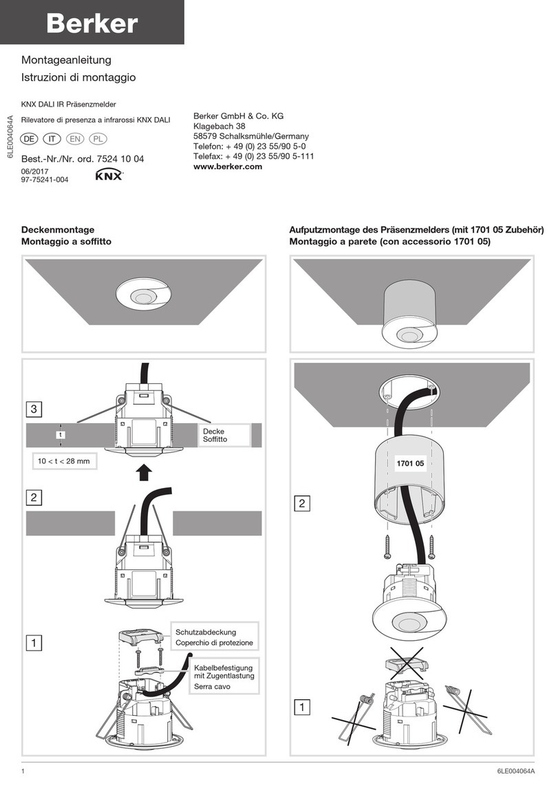
Deckenmontage
1. Mit einer Lochsäge ein Loch aussägen
Ø 60 - 63mm.
2. Montieren Sie die Schutzabdeckung über die
Anschlüsse und befestigen Sie die Schrauben.
3. Melder gemäß den Anweisungen des
Anschlussbildes anschließen.
4. Potentiometer mit den gewünschten
Einstellungen kongurieren.
Hinweis :
Die Stärke des Deckenmaterials, an dem Sie den
Melder befestigen, sollte zwischen 10 und 28mm
betragen.
Aufputzmontage des Präsenzmelders
(mit 1701 05 Zubehör)
1. Aufputzgehäuse an der Decke befestigen
2. Die beiden Federbügel am Präsenzmelder
entfernen.
3. Anschlüsse entsprechend anschließen.
4. Präsenzmelder einstecken und durch Drehen
xieren.
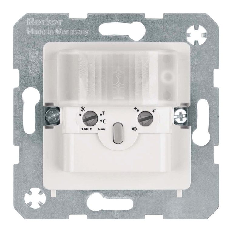
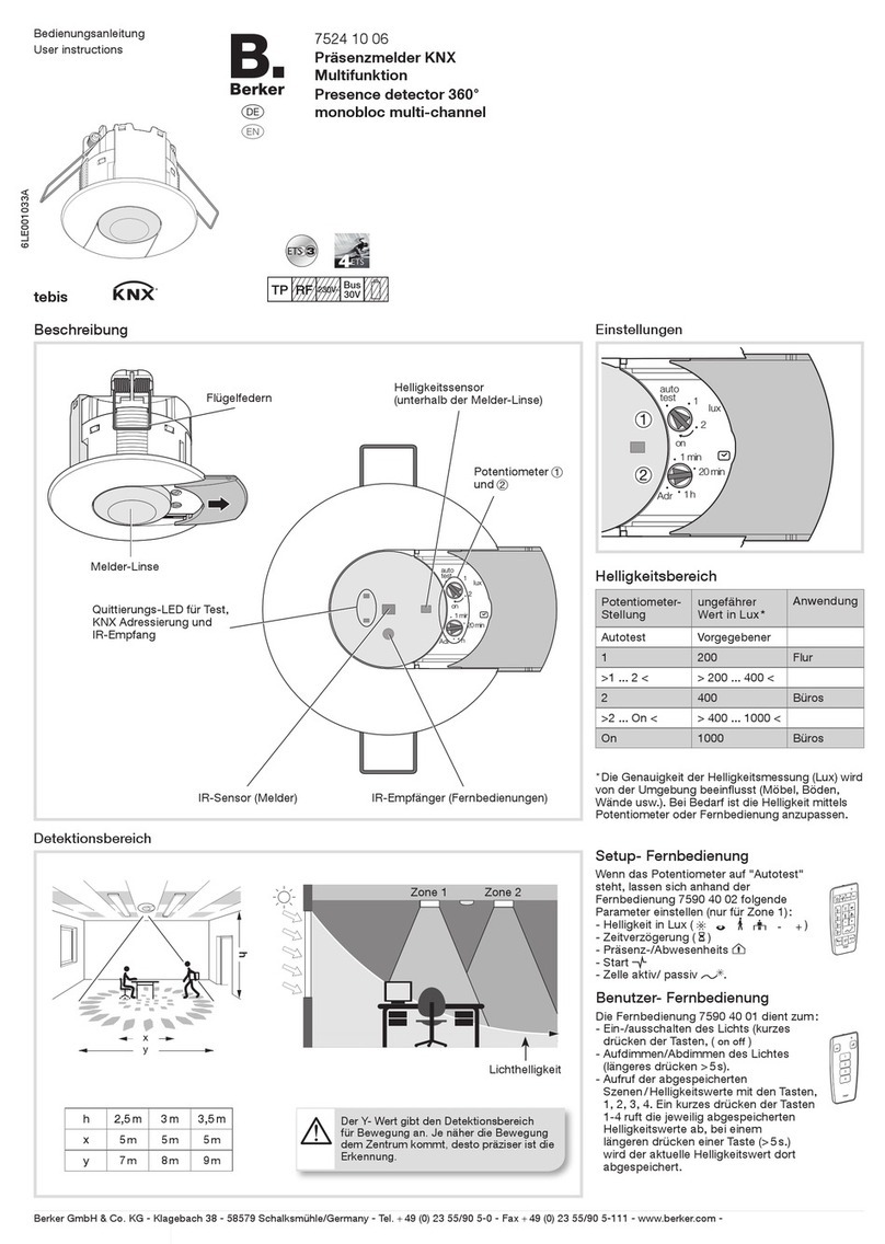
5. Die Potentiometer unter dem Schieber
einstellen.
Einbau
Optimale Leistungsmerkmale im Meldebetrieb
können nur erzielt werden, wenn die
nachstehenden Anweisungen beachtet werden:
- Empfohlene Installationshöhe: 2.5 m ➡3.5 m
- In Büroräumen ist der Melder direkt über dem
Arbeitsplatz zu installieren.
- Wenn sie mehrere Präsenzmelder in einem
Raum verwenden, achten sie darauf, das sich
die einzelnen Detektionsbereiche überschneiden
müssen.
- Umfeldbedingte Störungen (Wärmequellen,
Trennwände, Grünpanzen, Lüftungsaustritte
usw.) sind zu vermeiden.
Was tun…
• bei unplanmäßiger Auslösung der Beleuchtung?
Überprüfen, ob der Melder direkt einer Wärme-
bzw. Lichtquelle ausgesetzt ist oder sich
unterhalb eines Lüftungsauslasses bendet.
• bei ungenügender Reichweite des Melders?
Überprüfen, ob Einbauhöhe und Einbauort des
Melders optimal gewählt wurden.
Ceiling mounting
1. Cut out a 60 - 63mm diameter hole using a hole
saw.
2. Wire the detector according to the
recommended connection diagram.
3. Fix the detector by pushing both springs
upward then insert them into the hole.
4. Set potentiometers according to the desired
values.
Note :
The thickness of the support ceiling (t) must be
within 10 to 28mm range.
Surface mounting
(with accessory 1701 05)
1. Screw the accessory on the ush mounting box.
2. Remove the springs from the detector.
3. Wire the detector according to the
recommended connection diagram.
4. Push and turn the detector to lock it into the
accessory.
5. Open the slider to set the potentiometers
according to the desired values.
Implementation requirements
Requirements for optimal detection:
- Recommended installation distance from
ground: 2.5m ➡3.5m
- In ofces, the detector must be installed above
the workstation.
- When using several detectors, detection areas
shall overlap.
- Keep away from environmental disturbances
(heat sources, partitions, houseplants,
ventilation,...).
Trouble shooting
• False switching of lighting point:
Check that the detector is not exposed directly
to a heat source or a lighting source, or is not
placed above a ventilation grid...
• The range of the detector is too short:
Check whether the distance of the device
from the ground is sufcient and its location is
optimal.
Montaggio a softto
1. Praticare un foro di 60 - 63mm di diametro con
una fresa o un trapano.
2. Assemblare il rilevatore in base agli schemi di
collegamento raccomandati.
3. Fissare il rilevatore spingendo le due
molle verso l'alto, quindi inserirlo nel foro
precedentemente fatto.
4. Effettuare le regolazioni dei potenziometri.
Attenzione :
lo spessore di supporto nel softto (t) deve essere
compreso tra 10 e 28mm.
Montaggio a parete
(con accessorio 1701 05)
1. Avvitare l'accessorio sulla scatola;
2. Rimuovere dal rilevatore le mollette;
3. Collegare il rilevatore seguendo le indicazioni
dello schema elettrico di connessione;
4. Premere e girare il rilevatore per bloccarlo
all'interno dell'accessorio;
5. Aprire lo slider per regolare i potenziometri
secondo le proprie esigenze.
Messa in opera
Al ne di ottenere condizioni ottimali di rilevazione,
è opportuno attenersi alle seguenti
raccomandazioni:
- Altezza di installazione raccomandata: tra 2,5 e
3,5 metri.
- Negli ufci il rilevatore va installato direttamente
al di sopra del posto di lavoro.
- Durante l'utilizzo di più rilevatori, è necessario
che le zone di rilevazione si sovrappongano
parzialmente.
- Evitare le perturbazioni dovute all'ambiente (fonti
di calore, tramezzi, piante verdi, aerazione, ...).
Che cosa fare se…?
• Avviamento intempestivo del punto di
illuminazione:
Vericare che il rilevatore non sia direttamente
esposto ad una fonte di calore, ad una fonte
luminosa, che si trovi sopra ad una griglia di
aerazione…
• La portata del rilevatore è troppo debole:
Vericare che l'altezza di installazione e la
collocazione del rilevatore siano corrette.
6LE001032A - 02/2015
EeZzYy
bus
Anschluss / Connection / Collegamenti
Taster
Remote push button
Pulsanti
