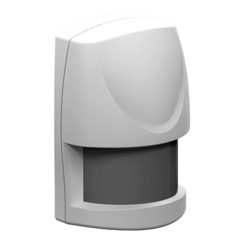
Berker 7524 10 04 User manual

06/2017
97-75241-004
Montageanleitung
Istruzioni di montaggio
Best.-Nr./Nr. ord. 7524 10 04
Berker GmbH & Co. KG
Klagebach 38
58579 Schalksmühle/Germany
Telefon: + 49 (0) 23 55/90 5-0
Telefax: + 49 (0) 23 55/90 5-111
www.berker.com
6LE004064A
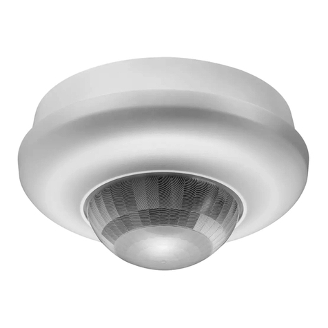
KNX DALI IR Präsenzmelder
Rilevatore di presenza a infrarossi KNX DALI
ezym
t
1
2
10 < t < 28 mm
1
2
3
Deckenmontage
Montaggio a sotto
Aufputzmontage des Präsenzmelders (mit 1701 05 Zubehör)
Montaggio a parete (con accessorio 1701 05)
1701 05
Decke
Sotto
Schutzabdeckung
Coperchio di protezione
Kabelbefestigung
mit Zugentlastung
Serra cavo
1 6LE004064A

Corretto smaltimento del prodotto
(rifiuti elettrici ed elettronici).
(Applicabile in i paesi dell'Unione Europea e in quelli con
sistema di raccolta dierenziata).
Il marchio riportato sul prodotto o sulla sua documentazio-
ne indica che il prodotto non deve essere smaltito con altri
rifiuti domestici al termine del ciclo di vita. Per evitare even-
tuali danni all'ambiente o alla salute causati dall'inopportu-
no smaltimento del rifiuti, si invita l'utente a separare ques-
to prodotto da altri tipi di rifiuti e di riciclarlo in maniera
responsabile per favorire il riutilizzo sostenibile delle risorse
materiali.
Gli utenti domestici sono invitati a contattare il rivenditore
presso il quale è stato acquistato il prodotto o l'ucio loca-
le preposto per tutte le informazioni relative alla raccolta
dierenziata e al riciclaggio per questo tipo di prodotto.
Gli utenti aziendali sono invitati a contattare il proprio forni-
tore e verificare i termini e le condizioni del contratto di
acquisto. Questo prodotto non deve essere smaltito unita-
mente ad altri rifiuti commerciali.
Korrekte Entsorgung dieses Produkts
(Elektromüll).
(Anzuwenden in den Ländern der Europäischen Union und ande-
ren europäischen Ländern mit einem separaten Sammelsystem).
Die Kennzeichnung auf dem Produkt bzw. auf der dazugehörigen
Literatur gibt an, dass es nach seiner Lebensdauer nicht zusam-
men mit dem normalen Hausmüll entsorgt werden darf. Entsorgen
Sie dieses Gerät bitte getrennt von anderen Abfällen, um der Um-
welt bzw. Der menschlichen Gesundheit nicht durch unkontrollier-
te Müllbeseitigung zu schaden. Recyceln Sie das Gerät, um die
nachhaltige Wiederverwertung von stoichen Ressourcen zu
fördern. Private Nutzer sollten den Händler, bei dem das Produkt
gekaut wurde, oder die zuständigen Behörden kontaktieren, um in
Erfahrung zu bringen, wie sie das Gerät auf umweltfreundliche
Weise recyceln können.
Gewerbliche Nutzer sollten sich an ihren Lieferanten wenden und die
Bedingungen des Verkaufsvertrags konsultieren. Dieses Produkt darf
nicht zusammen mit anderem Gewerbemüll entsorgt werden.
Montaggio a sotto
1. Praticare un foro di 60-63mm di diametro con
una fresa o un trapano.
2. Fissare il rilevatore spingendo le due molle verso
l'alto, quindi inserirlo nel foro precedentemente
fatto.
3. Assemblare il rilevatore in base agli schemi di
collegamento raccomandati.
4. Fissare il coperchio di protezione con le viti,fis-
sando il serra cavo.
5. Eettuare le regolazioni dei potenziometri.
Attenzione:
lo spessore di supporto nel sotto (t) deve essere
compreso tra 10 e 28 mm.
Montaggio a parete
(con accessorio 1701 05)
1. Avvitare l'accessorio sulla scatola;
2. Rimuovere dal rilevatore sia la calotta di
protezione che le mollette;
3. Collegare il rilevatore seguendo le indicazioni
dello schema elettrico di connessione;
4. Premere e girare il rilevatore per bloccarlo
all'interno dell'accessorio;
5. Aprire lo slider per regolare i potenziometri
secondo le proprie esigenze.
Messa in opera
Al fine di ottenere condizioni ottimali di rilevazione, è
opportuno attenersi alle seguenti raccomandazioni:
- Altezza di installazione raccomandata: tra 2,5 e
3,5 metri.
- Negli uci il rilevatore va installato direttamente al
di sopra del posto di lavoro.
- Durante l'accoppiamento di più rilevatori, è neces-
sario che le zone di rilevazione si sovrappongano
parzialmente.
- Evitare le perturbazioni dovute all'ambiente (fonti
di calore, tramezzi, piante verdi, aerazione ecc).
Deckenmontage
1. Mit einer Lochsäge ein Loch aussägen
Ø 60-63mm.
2. Melder gemäß den Anweisungen des
Anschlussbildes anschließen.
3. Montieren Sie die Schutzabdeckung über
die Anschlüsse und befestigen Sie die
Schrauben.
4. Melder befestigen, indem Sie die 2
Federbügel nach oben drücken und den
Melder in das zuvor ausgeschnittene Loch
einführen.
5. Potentiometer mit den gewünschten
Einstellungen konfigurieren.
Hinweis:
Die Stärke des Deckenmaterials, an dem Sie
den Melder befestigen, sollte zwischen 10 und
28 mm betragen.
Aufputzmontage des
Präsenzmelders
(mit 1701 05 Zubehör)
1. Aufputzgehäuse an der Decke befestigen
2. Schutzabdeckung und die beiden
Federbügel am Präsenzmelder entfernen.
3. Anschlüsse entsprechend anschließen.
4. Präsenzmelder einstecken und durch
Drehen fixieren.
5. Die Potentiometer unter dem Schieber
einstellen.
Einbau
Optimale Leistungsmerkmale im Meldebetrieb
können nur erzielt werden, wenn die nachste-
henden Anweisungen beachtet werden:
- Empfohlene Installationshöhe:
2.5 m —> 3.5 m
- In Büroräumen ist der Melder direkt über
dem Arbeitsplatz zu installieren.
- Bei Verbundschaltung mehrer Melder müssen
die Erfassungsbereiche einander überlappen.
- Umfeldbedingte Störungen (Wärmequellen,
Trennwände, Grünpflanzen, Lüftungsaustritte
usw.) sind zu vermeiden.
Was tun…
• bei unplanmäßiger Auslösung der Beleuchtung?
Überprüfen, ob der Melder direkt einer Wärme-
bzw. Lichtquelle ausgesetzt ist oder sich unterhalb
eines Lüftungsauslasses befindet.
• bei ungenügender Reichweite des Melders?
Überprüfen, ob Einbauhöhe und Einbauort des
Melders optimal gewählt wurden.
• bei der Beleuchtungsreglung auf einem
niedrigen Helligkeitsniveaus, kann es zum
flakern der Beleuchtungsmittel kommen:
Überprüfen Sie die Dimmung-vorgaben des
benutzten Beleuchtungsmittel und benutzen
Sie vorzugsweise dann die 1-100%.
Werkseinstellungen
Helligkeitswert 400 lux
Abschaltverzögerung 20 Min.
Betriebsart Anwesenheit
Start OFF
Zelle aktiv (Helligkeitszelle) ON
Technische Spezifikation
Elektrische Merkmale
Versorgungsspannung (für das Produkt):
KNX Bus 30V s
Versorgungsspannung (DALI/DSI-Bus):
230V v+10/-15% 50/60Hz
240V v +/-6% 50/60Hz
Busbelastung: 12mA / Netzbelastung 60mW
Maximale Anzahl DALI/DSI Geräte: 24
Funktionsdaten
Einschaltdauer Beleuchtungsausgang :
1Min. —> 1Std
Helligkeitswert: 5 —> 1000 Lux
Empfohlene Installationshöhe: 2,5 —> 3,5m
Meldebereich: Ø 7m (Installationshöhe: 2,5m)
Die Geräte können parallel geschaltet werden.
Bohrungsdurchmesser: 60mm
Umgebungsbedingungen
Betriebstemperatur: -10 °C —> +45 °C
N
LN
L
230 V
ballast
da+ da-
DALI ballast
Remote push button
Remote load
bus
Remote push button
Remote load
Anschluss / Aansluitingen
Taster
Pulsanti
E
Y
Che cosa fare se…?
• Avviamento intempestivo del punto di illumi-
nazione:
Verificare che il rilevatore non sia direttamente
esposto ad una fonte di calore, ad una fonte
luminosa, che si trovi sopra ad una griglia di
aerazione…
• La portata del rilevatore è troppo debole :
Verificare che l'altezza di installazione e la
collocazione del rilevatore siano corrette.
• La regolazione su livelli di luminosità bassi-
non è stabile:
Verificare la spiaggia di variazione delle
zavorre ed utilizzare possibilmente zavorre
1-100%.
Specifiche tecniche
Caratteristiche elettriche
Tensione d’alimentazione (per il prodotto):
KNX bus 30V s
Tensione d’alimentazione (DALI/DSI bus):
230V v+10/-15% 50/60Hz
240V v +/-6% 50/60Hz
Consumo a vuoto: 12mA sull’ bus /
60mW sulla corrente
DALI / DSI capicità di comando: 24 ballast
Caratteristiche funzionali
Durata di funzionamento uscita illuminazione:
1min. —> 1h
Soglia di luminosità : 5 —> 1000 Lux
Altezza d’installazione raccomandata: 2,5 —> 3,5m
Zona di rilevazione: Ø 7m
(altezza d’installazione: 2,5m)
E’ possibile collegare gli articoli in parallelo.
Diametro di foratura: 60mm
Ambiente
Ta di funzionamento: -10 °C —> +45 °C
Ta stoccaggio : -20 °C —> +60 °C
Classe d’isolamento : II
IK 03
Indice di protezione : IP41
Resistenza al fuoco : 650°C
Mezzo di comunicazione KNX: TP1
Modalità di congurazione KNX : S-mode
Capacità di collegamento
Flessibile: 0.5mm2—> 0,75mm2,
Rigido : 0.5mm2—> 0,75mm2
Lagerungstemperatur: -20 °C —> +60 °C
Isolationsklasse: II
IK 03
Schutzart: IP41
Feuerbeständigkeit: 650°C
KNX Medium: TP1
KNX Konfigurationsmodus: S-mode
Anschlusskapazität
Flexibel: 0.5mm2—> 0,75mm2,
Massiv: 0.5mm2—> 0,75mm2
Impostazioni di fabbrica
Soglia di luminosità 400 lux
Temporizzazione 20 min.
Modalità Presenza
Avviamento OFF
Cellula attiva (cellula di luminosità) ON
Verwendbar in ganz Europa
å
und in der Schweiz
Utilizzabile in tutta Europa åe in Svizzera
2 6LE004064A

Order no./Nr zamówieniowy 7524 10 04
06/2017
97-75241-004
Installation instructions
Instrukcja montażu
Berker GmbH & Co. KG
Klagebach 38
58579 Schalksmühle/Germany
Telefon: + 49 (0) 23 55/90 5-0
Telefax: + 49 (0) 23 55/90 5-111
www.berker.com
6LE004064A
KNX DALI IR presence detector
Czujnik obecnosci na podczerwień KNX DALI
ezym
t
1
2
10 < t < 28 mm
1
2
3
Ceiling mounting
Montaż sufitowy Surface mounting (with accessory 1701 05)
Mocowanie zewnętrzne (z elementem dodatkowym 1701 05)
1701 05
Ceiling Sufit
Protective cover
Osłona
Cable clamp
Zacisk przewodu
3 6LE004064A

Correct Disposal of This product
(Waste Electrical & Electronic Equipment)
(Applicable in the European Union and other European countries
with separate collection systems).
This marking shown on the product or its literature indicates that
it should not be disposed with other household wasted at the end
of its working life. To prevent possible harm to the environment or
human health from uncontrolled waste disposal, please separate
this from other types of wastes and recycle it responsibly to
promote the sustainable reuse of material resources. Household
users should contact either the retailer where they purchased this
product, or their local government office, for details of where and
how they can take this item for environmentally safe recycling.
Business users should contact their supplier and check the terms
and conditions of the purchase contract. This product should not
be mixed with other commercial wastes of disposal.
Z
M
N
LN
L
230 V
ballast
da+ da-
DALI ballast
Remote push button
Remote load
bus
Remote push button
Remote load
Connection / Podłączenie
Remote push button
Przycisk zdalny
Montaż sufitowy
1. Za pomocą piły otwornicowej wyciąć otwór o
średnicy 60-63 mm.
2. Zamontować detektor poprzez skierowanie ku
górze obu sprężyn i wprowadzenie ich do otwo-
ru.
3. Podłączyć detektor zgodnie z zaleceniami zawar-
tymi w schemacie połączeń.
4. Zamocować osłonę zacisków i przykręcić zacisk
przewodu.
5. Ustawić potencjometry zgodnie z pożądanymi
wartościami.
Uwaga:
Grubość sufitu (t) musi zawierać się w zakresie od
10 do 28 cm.
Mocowanie zewnętrzne
(z elementem dodatkowym 1701 05)
1. Przykręcić element do puszki podtynkowej mon-
tażowej.
2. Usunąć spężyny z detektora.
3. Podłączyć przewody do detektora zgodnie z
zaleceniami zawartymi w schemacie połączeń.
4. Wcisnąć i obrócić detektor dla zblokowania w
elemencie dodatkowym.
5. Otworzyć klapkę i ustawić potencjometry
zgodnie z pożądanymi wartościami.
Wymagania dotyczące wykonania
Wymagania dla optymalnej detekcji:
- Zalecany odległość montażu od ziemi:
2,5 m —> 3,5 m
- W biurach detektor musi być zamontowany nad
stacjami roboczymi.
- Przy użyciu kilku detektorów, obszary detekcji
powinny na siebie nachodzić.
- Trzymać z dala od zakłóceń środowiskowych
(źródeł ciepła, przegród, roślin doniczkowych,
wentylacji...).
Usuwanie problemów
• Błędne włączanie punktu świetlnego :
Sprawdzić czy detektor nie jest wystawiony na
bezpośrednie działanie źródła ciepła lub światła, lub
czy nie jest umieszczony nad siecią wentylacyjną...
• Zasięg detektora jest za mały :
Ceiling mounting
1. Cut out a 60-63mm diameter hole using a
hole saw.
2. Fix the detector by pushing both springs
upward then insert them into the hole.
3. Wire the detector according to the
recommended connection diagram.
4. Mount the protective cover over the
terminals and screw the cable clamp.
5. Set potentiometers according to the
desired values.
Note:
The thickness of the support ceiling (t) must
be within 10 to 28mm range.
Surface mounting
(with accessory 1701 05)
1. Screw the accessory on the flush mounting
box.
2. Remove the protective cover and the
springs from the detector.
3. Wire the detector according to the
recommended connection diagram.
4. Push and turn the detector to lock it into
the accessory.
5. Open the slider to set the potentiometers
according to the desired values.
Implementation requirements
Requirements for optimal detection:
- Recommended installation distance from
ground: 2.5 m —> 3.5 m
- In oces, the detector must be installed
above the workstation.
- When associating several detectors,
detection areas shall overlap.
- Keep away from environmental disturbances
(heat sources, partitions, houseplants,
ventilation...).
Trouble shooting
• False switching of lighting point :
Check that the detector is not exposed directly
to a heat source or a lighting source, or is not
placed above a ventilation grid...
• The range of the detector is too short :
Check whether the distance of the device from
the ground is sucient and its location is optimal.
• The light regulation on low brightness levels
may fluctuate: check the dimming range of the
used ballasts and use preferably 1-100%
devices.
Technical features
Electrical characteristics
Supply voltage (for the product):
KNX bus 30V s
Supply voltage (DALI/DSI bus):
230V v+10/-15% 50/60Hz
240V v+/-6% 50/60Hz
Consumption with no load: 12mA on the bus /
60mW on mains
DALI/ DSI output capacity: 24 ballasts
Functional characteristics
Lighting output operating time: 1 min. —> 1 h
Brightness level: 5 —> 1000 Lux
Recommended installation height:
2,5 m —> 3,5m
Detection range: Ø 7m (installed product
height: 2.5m)
Products can be connected in parallel.
Hole size required: 60mm
Environment
Operating temperature: -10 °C —> +45 °C
Storage temperature: -20 °C —> +60 °C
Class of insulation: II
IK 03
Index of protection: IP41
Fire resistance: 650°C
KNX medium: TP1
KNX Configuration Mode: S-mode
Connection capacity:
0.5mm2to 0,75mm2flexible,
0.5mm2to 0,75mm2rigid
Sprawdzić czy odległość urządzenia od ziemi
jest wystarczająca i lokalizacja optymalna.
• Przy niskim poziomie jasności podczas regu-
lacji światło może migać:
sprawdzić zakres ściemniania zastosowanych
stateczników żarówek; korzystać z urządzeń
pracujących w zakresie 1 – 100%.
Dane techniczne
Charakterystyka elektryczna
Napięcie zasilania (dla produktu):
szyna KNX 30V s
Napięcie zasilania (szyna DALI/DSI):
230V v+10/-15% 50/60Hz
240V v +/-6% 50/60Hz
Pobór mocy bez obciążenia: 12 mA na szynie /
60 mW w sieci zasilającej
Pojemność wyjściowa DALI/DSI: 24 obciążenia
Charakterystyka funkcjonalna
Czas pracy oświetlenia: 1 min —> 1 godz.
Poziom jasności: 5 —> 1000 luksów
Zalecana wysokość montażu:
2,5 m —> 3,5m
Zakres detekcji: Ø 7m
(wysokość montażu produktu: 2,5 m)
Produkty można połączyć równolegle.
Wymagana średnica otworu: 60 mm
Środowisko
Temperatura pracy: -10 °C —> +45 °C
Temperatura przechowywania:
-20 °C —> +60 °C
Klasa izolacji: II
IK 03
Stopień ochrony: IP41
Odporność ogniowa: 650°C
Medium komunikacyjne KNX: TP1
Tryb konfiguracji KNX: S-mode
Przekrój przyłączy:
od 0,5 mm2do 0,75 mm2giętkie,
od 0,5 mm2do 0,75 mm2sztywne
Prawidłowe usuwanie produktu
(zużyty sprzęt elektryczny i
elektroniczny).
Oznaczenie umieszczone na produkcie lub w odnoszących
do niego tekstach wskazuje, że produkt po upływie okresu
użytkowania nie należy usuwać z innymi odpadami pocho-
dzącymi z gospodarstw domowych. Aby uniknąć szkodli-
wego wpływu na środowisku naturalne i zdrowie ludzi ws-
kutek niekontrolowanego usuwania odpadów, prosimy o
oddzielenie produktu od innego typu odpadów oraz odpo-
wiedzialny recycling w celu promowania ponownego uży-
cia zasobów materialnych jako dobrej praktyki.
W celu uzyskania informacja na temat miejsca i sposobu
bezpiecznego dla środowiska recyklingu tego produktu
użytkownicy w gospodarstwach domowych powinni skon-
taktować się z punktem sprzedaży detalicznej, w którym
dokonali zakupu produktu lub organem władz lokalnych.
Użytkownicy w firmach powinni skontaktować się ze
swoim dostawca i sprawdzić warunki umowy zakupu. Pro-
duktu nie należy usuwać z innymi odpadami komercyjnymi.
Factory settings
Luminosity threshold 400 lux
Lighting time 20 min.
Mode Presence
Power Up OFF
Active cell
(Luminosity Cell) ON
Ustawienia fabryczne
Próg siły światła 400 luksów
Czas oświetlenia 20 min
Tryb Obecność
Włączanie zasilania OFF (wył.)
Aktywna fotokomórka (foto-
komórka siły światła) ON (wł.)
Usable throughout Europ
e å
and in Switzerland
Nadaje się do użytku w krajach europejskich
å
i Szwajcarii
4 Berker GmbH & Co. KG - Klagebach 38 - 58579 Schalksmühle/Germany - Tel. + 49 (0) 23 55/90 5-0 Fax + 49 (0) 23 55/90 5-111 - www.berker.com
6LE004064A
Other Berker Security Sensor manuals

Berker
Berker 1701 11 Service manual

Berker
Berker 1701 10 Service manual

Berker
Berker 9420 Series Service manual
Berker
Berker 7524 10 05 Operating manual
Berker
Berker 7524 10 03 User manual
Berker
Berker BLC 360 User manual

Berker
Berker 85801100 User manual

Berker
Berker 7566 27 Series User manual
Berker
Berker Radio Detector 180 User manual
Berker
Berker 143 99 09 Service manual

Berker
Berker BLC User manual
Berker
Berker BLC Service manual
Berker
Berker 7524 10 06 User manual

Berker
Berker 9420 Series User manual
Berker
Berker Control 220 Service manual

Berker
Berker 174 01 09 Service manual
Berker
Berker 2996 User manual

Berker
Berker BLC 1784 Series Service manual

Berker
Berker 1701 08 User manual

Berker
Berker 102 09 Service manual
