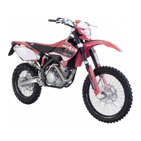
Beta X-Trainer 300 2T User manual

1GB
X-TRAINER 300 2T
Thanks for you preference, and have a good time! This hand-
book contains the information you need to properly operate and
maintain your motorcycle.
The data, specifications and images shown in this manual does not constitute
an engagement on the part of BETAMOTOR S.p.A. BETAMOTOR reserves
the right to make any changes and improvements to its models at any mo-
ment and without notice.
Code 036440040 000

2
GB
IMPORTANT
We recommend you to check all the tightenings after the first one
or two hours’ ride over rough ground. Special attention should
be paid to the following parts:
•rear sprocket
•ensure that the footrests are properly fixed
•front/rear brake levers/calipers/discs
•check that the plastics are properly fastened
•engine bolts
•shock absorber bolts/swingarm
•wheel hubs/spokes
•rear frame
•pipe connections
•tensioning the chain
IMPORTANT
In the event of interventions on the vehicle, contact Betamotor
after-sales service.

CONTENTS
3GB
CONTENTS
Operating instructions............................................................................. 5
Symbols................................................................................................5
Riding safety ......................................................................................... 6
CHAPTER 1 GENERAL INFORMATION ..............................................7
Vehicle identification data .......................................................................8
Tools kit ................................................................................................ 8
Familiarizing with the vehicle...................................................................9
Specifications ......................................................................................10
Electrical system...................................................................................14
Recommended lubricants and liquid .......................................................16
CHAPTER 2 OPERATION .................................................................. 17
Main parts .......................................................................................... 18
Digital rpm indicator operating instructions..............................................23
Checks before and after use..................................................................29
Running in........................................................................................... 29
Refuelling............................................................................................ 30
Oil mixer refuelling ..............................................................................31
Starting the engine ............................................................................... 31
Engine shut-down................................................................................. 31
CHAPTER 3 ADJUSTMENTS..............................................................33
Key to symbols.....................................................................................34
Brakes ................................................................................................34
Clutch................................................................................................. 34
Adjustment of gas clearance..................................................................35
Adjusting the idle speed........................................................................35
Exhaust valve control adjustment ............................................................ 38
Handlebar adjustment .......................................................................... 38
Adjusting fork ...................................................................................... 39
Shock absorber....................................................................................40
CHAPTER 4 CHECKS AND MAINTENANCE .....................................43
Key to symbols.....................................................................................44
Engine oil............................................................................................44
Liquid coolant...................................................................................... 45
Air filter .............................................................................................. 48
Spark plug .......................................................................................... 49
CONTENTS
4
GB
Carburettor .........................................................................................50
Front brake..........................................................................................52
Rear brake .......................................................................................... 55
Clutch control ...................................................................................... 58
Check and adjusting of steering play...................................................... 60
Front wheel ......................................................................................... 61
Fork.................................................................................................... 62
Rear suspension leverage...................................................................... 62
Tyres...................................................................................................63
Chain .................................................................................................63
Headlight............................................................................................ 65
Replacing the headlight bulbs................................................................65
Tail light.............................................................................................. 65
Battery................................................................................................ 66
Fuses ..................................................................................................68
Cleaning the vehicle............................................................................. 69
Prolonged inactivity.............................................................................. 70
Scheduled maintenance vehicle .............................................................71
Tightening torque overview ................................................................... 73
CHAPTER 5 REPLACEMENTS ............................................................75
Removal and refitting of the saddle.........................................................76
Removing and installing air filter cover panel........................................... 77
CHAPTER 6 TROUBLESHOOTING .................................................... 79
Troubleshooting ...................................................................................80

5GB
OPERATING INSTRUCTIONS
•The vehicle must be accompanied by: number-plate, registration document, tax
disc and insurance.
•Any modifications of the engine or other parts are punishable by severe sanctions
including the confiscation of the vehicle.
•To protect your safety and that of others, always drive carefully and with your helmet
on and always keep low beams on.
•Do not sit on the vehicle when it is on its stand.
•Do not start the engine in closed places.
WARNING
Any modifications and tampering with the vehicle during the warranty period exempt
the manufacturer from all responsibility and invalidate warranty.
SYMBOLS
SAFETY/ATTENTION
Failure to respect information marked with this symbol can entail a personal
hazard.
INTEGRITY OF THE VEHICLE
Failure to respect information marked with this symbol can entail serious dam-
age to the vehicle and termination of the warranty.
FLAMMABLE LIQUID HAZARD
Read the use and maintenance manual carefully.
MANDATORY TO WEAR PROTECTIVE CLOTHING
Use of the vehicle is subject to wearing specific protective clothing and safety
footwear.
PROTECTIVE GLOVES MANDATORY
To perform the operations described, it is mandatory to wear protective gloves
.
FORBIDDEN TO USE NAKED FLAMES OR POSSIBLE UNCONTROLLED IGNI-
TION SOURCES
NO SMOKING
DO NOT USE MOBILE PHONE
CORROSIVE SUBSTANCES HAZARD
Liquids marked with this symbol are highly corrosive: handle with care
POISONING HAZARD

6
GB
RIDING SAFETY
•Observe the Highway Code.
•Always wear approved personal protective equipment.
•Always ride with the low beam on.
•Always keep the crash helmet visor clean.
•Avoid wearing garments with hanging ends.
•Do not keep sharp or brittle objects in your pockets while riding.
•Properly adjust the rearview mirrors.
•Always ride in a seated position, with both hands on the handlebars and both feet
on the footrests.
•Never ride abreast with other vehicles.
•Do not tow and avoid being towed by other vehicles.
•Always keep a safe distance from other vehicles.
•Do not start off while the vehicle is on its stand.
•Avoid swaying and wheelies as they are extremely dangerous for your own and
other people’s safety as well as for your vehicle.
•Always apply both brakes on dry roads with no gravel and sand. Using one brake
may be dangerous and cause uncontrolled skidding.
•To reduce the braking distance, always apply both brakes.
•On wet roads and in off-road riding, drive with care and at moderate speed. Take
special care in applying the brakes.

1
GENERAL INFORMATION
7GB
CHAPTER 1 GENERAL INFORMATION
CONTENTS
Vehicle identification data .......................................................................8
Frame identification ........................................................................... 8
Engine identification .......................................................................... 8
Tools kit ................................................................................................ 8
Familiarizing with the vehicle...................................................................9
Main parts:....................................................................................... 9
Specifications ......................................................................................10
Weight........................................................................................... 10
Dimensions .....................................................................................10
Tyres.............................................................................................. 10
Capacities......................................................................................10
Front suspension.............................................................................. 11
Rear suspension .............................................................................. 11
Front brake..................................................................................... 11
Rear brake ..................................................................................... 11
Engine ...........................................................................................12
Electrical system...................................................................................14
Electrical diagram ........................................................................... 14
Legend electrical diagram ................................................................ 15
Recommended lubricants and liquid .......................................................16

1
GENERAL INFORMATION
8
GB
VEHICLE IDENTIFICATION
DATA
FRAME IDENTIFICATION
Frame identification data Aare stamped
on the right side of the steering head tube.
ENGINE IDENTIFICATION
Engine identification data Bare stamped
in the area shown in the figure.
TOOLS KIT
The following items are supplied as stand-
ard: operation and maintenance manual,
tool kit.
B
Inside the battery compartment you will
find the hexagon wrench 3 and the socket
wrench (8 mm). To gain access remove the
saddle (page 76).
3
A

1
GENERAL INFORMATION
9GB
MAIN PARTS:
1 - Fuel tank
2 - Tank cap
3 - Silencer
4 - Rear shock absorber
5 - Headlight
6 - Rear light
7 - Side stand
8 - Fork
9 - Rider’s footrests
10 - Lower bumper
(Bumper kit)
11 - Saddle
12 - Engine
13 - Front mudguard
14 - Number-plate holder
15 - Side panel air filter
cover
16 - Front side panel
17 - Rear side panel
18 - Fork covers
19 - Rear mudguard
5
8
21
11
19
14
12
9
4
6
3
10
13
18
15
7
9
FAMILIARIZING WITH THE VEHICLE
17 16

1
GENERAL INFORMATION
10
GB
SPECIFICATIONS
WEIGHT
Dry weight .................................................99 kg (front 48 Kg; rear 51 Kg)
DIMENSIONS
maximum length......................................................................... 2157 mm
maximum width ........................................................................... 802 mm
overall height ............................................................................ 1245 mm
wheelbase................................................................................. 1467 mm
saddle height............................................................................... 910 mm
ground clearance......................................................................... 320 mm
footrest height.............................................................................. 390 mm
TYRES
CAPACITIES
fuel tank......................................................................................8,5 liters
including reserve..........................................................................1,5 liters
coolant circuit..............................................................................1,3 liters
mixer oil tank ............................................................................0,55 liters
including reserve........................................................................0,21 liters
gear oil.....................................................................................0,85 liters
Dimensions Pressure [Bar]
Front tyre Rear tyre Front tyre Rear tyre
80/100-21 140/80-18
1,5 (road use) 1,8 (road use)
1 (off-road use) 1 (off-road use)

1
GENERAL INFORMATION
11 GB
FRONT SUSPENSION
Hydraulic fork USD (shafts Ø43 mm)
Spring ............................................................................................... K 8
Oil type ............... see table “Recommended lubricants and liquids”, page 16
Oil quantity ...................................................................................500 ml
Spring preload register ......................................................completely open
Rebound clicks (from completely closed).................................................. 12
Wheel travel................................................................................270 mm
REAR SUSPENSION
Single shock absorber with compound lever
Spring ............................................................................................ K 5,2
Static sag load (see page 41).......................................................... 22 mm
Compression clicks, high speeds (from completely closed).........................15
Rebound clicks (from completely closed).................................................. 10
Shock absorber travel................................................................... 110 mm
FRONT BRAKE
Ø260 mm disc and dual-piston floating caliper
REAR BRAKE
Ø240 mm disc and single-piston floating caliper

1
GENERAL INFORMATION
12
GB
ENGINE
Type ................................................. Single-cylinder, 2-stroke, liquid cooled
and electric start
Bore x stroke ......................................................................... 72 x 72 mm
Displacement (cm3)....................................................................293,1 cm3
Compression ratio.......................................................................... 11,3:1
Fuel system.................................................carburettor with electronic mixer
Carburettor
X-TRAINER 300
Version Certif. Competition*
Carburettor type PWK 36S AG
Main jet 118 155
Slow jet 38 35
Start jet 50 85
Needle N84K N1EJ
Needle position (from top) 4° 2°
Air screw turns (from all closed) 1 1+1/2
Valve 7,5
Striker YES NO
Cooling system ......................................... forced liquid circulation by pump
Spark plug ......................................................................NGK IR GR7CI-8
Clutch.................................................................................. wet, multidisc
* - Such modification makes the vehicle non-compliant with the road regula-
tions in force. Its use must be limited to the sole private circuits which are
closed to circulation.

1
GENERAL INFORMATION
13 GB
Gearchange
Exhaust valve................................centrifugal operation with reaction springs
Ignition ................................................................ DC-CDI without trembler,
with digital variable spark advance, Kokusan-type
Starting............................................................................... electric starter
Version X-TRAINER 300
Primary drive 28/70
Gear ratio 1st gear 12/31
Gear ratio 2nd gear 15/28
Gear ratio 3rd gear 19/28
Gear ratio 4th gear 20/24
Gear ratio 5th gear 27/27
Gear ratio 6th gear 28/24
Final drive Certif. Competition*
15/45 13/51
* - Such modification makes the vehicle non-compliant with the road
regulations in force. Its use must be limited to the sole private circuits
which are closed to circulation.

1
GENERAL INFORMATION
14
GB
ELECTRICAL SYSTEM
ELECTRICAL DIAGRAM
Key to colours
Bi = White
Ve = Green
Ma= Brown
Vi = Purple
Bl = Blue
Ne = Black
Gi = Yellow
Rs = Red
Ar = Orange
Az = Sky-blue
Ro = Pink
Gr = Grey

1
GENERAL INFORMATION
15 GB
LEGEND ELECTRICAL DIAGRAM
1) RIGHT-HAND FRONT TURN INDICATOR 12V 6W
2) FRONT BRAKE LIGHT BUTTON
3) START BUTTON
4) WHEEL REVOLUTION SENSOR
5) TURN INDICATORS WARNING LIGHT
6) OIL RESERVE WARNING LIGHT
7) DASHBOARD
8) HEADLIGHT TELL TALE LAMP
9) MIXER DIAGNOSIS WARNING LIGHT
10) ENGINE STOP BUTTON
11) HORN BUTTON
12) HEADLIGHT SELECTOR
13) TURN SIGNAL LAMPS SWITCH
14) LEFT-HAND CONTROL GROUP
15) LEFT-HAND FRONT TURN INDICATOR 12V 6W
16) REGULATOR
17) ELECTRIC FAN
18) THERMOSWITCH
19) UNIT TURN SIGNAL LAMPS
20) LEFT-HAND REAR TURN INDICATOR (12V 6W BULB)
21) TAIL LIGHT WITH LED
22) NUMBER-PLATE LIGHT
23) RIGHT-HAND REAR TURN INDICATOR (12V 6W BULB)
24) REAR STOP BUTTON
25) FRAME EARTH
26) BATTERY 12V 4AH
27) BATTERY NEGATIVE TERMINAL
28) BATTERY POSITIVE TERMINAL
29) STARTER RELAY
30) STARTER MOTOR
31) 10A FUSE
32) CHARGER DIODES GROUP
33) CONDENSATOR 4700 μF
34) MIXER OIL PUMP
35) GENERATOR
36) ELECTRONIC CONTROL UNIT
37) TPS
38) HT COIL
39) SPARK PLUG
40) FRAME EARTH
41) OIL RESERVE SENSOR
42) PARKING LIGHT 12V 5W
43) HEADLIGHT (12V-35/35W BULB)
44) 12V HORN

1
16
GB
RECOMMENDED LUBRICANTS AND LIQUID
To maximize the vehicle’s performance and ensure many years of trouble-free opera-
tion, we recommend using the following products:
Note:
It is essential that all renewals should be performed with the products listed in the
table above.
PRODUCT TYPE SPECIFICATIONS
OIL MIXER TANK LIQUI MOLY 2-STROKE MOTOR OIL,
SELF-MIXING
GEAR AND CLUTCH OIL LIQUI MOLY RACING 10W40
BRAKE OIL LIQUI MOLY BRAKE FLUID DOT 5.1
CLUTCH ACTUATOR OIL LIQUI MOLY BRAKE FLUID DOT 5.1
FORK OIL SAE 5W
TIE ROD GREASE LIQUI MOLY SCHMIERFIX
LIQUID COOLANT LIQUI MOLY COOLANT READY MIX
RAF12 PLUS

2
OPERATION
17 GB
CHAPTER 2 OPERATION
CONTENTS
Main parts .......................................................................................... 18
Fuel tank cap ..................................................................................18
Fuel cock........................................................................................ 18
Starter............................................................................................ 19
Mixer oil tank cap ........................................................................... 19
Clutch lever .................................................................................... 19
LH switch........................................................................................ 20
Starter button .................................................................................. 20
Front brake lever and gas control ......................................................20
Gear change lever...........................................................................21
Brake pedal....................................................................................21
Side stand ...................................................................................... 21
Keys ..............................................................................................21
Steering lock...................................................................................22
Digital rpm indicator operating instructions..............................................23
Checks before and after use..................................................................29
Running in........................................................................................... 29
Refuelling............................................................................................ 30
Oil mixer refuelling ..............................................................................31
Starting the engine ............................................................................... 31
Engine shut-down................................................................................. 31

2
OPERATION
18
GB
MAIN PARTS
FUEL TANK CAP
To open the fuel tank cap, turn it anticlock-
wise.
To close the fuel tank cap, set it on the tank
and screw it clockwise.
FUEL COCK
Fuel cock has three positions:
OFF: fuel supply closed. Fuel cannot pass
from the tank to the carburettor.
ON: fuel supply enabled. Fuel flows from
the tank to the carburettor. The tank empties
until it reaches the reserve level.
RES: reserve fuel supply. Fuel flows from
the tank to the carburettor and the tank
empties completely.

2
OPERATION
19 GB
CLUTCH LEVER
Clutch lever is fitted to the left-hand side of
the handlebars.
STARTER
The starter lever is located on the carbu-
rettor.
To operate the choke pull it upward.
MIXER OIL TANK CAP
The mixer oil tank cap is located under
the saddle
To gain access remove the saddle (page
76).
To open the fuel tank cap turn it anticlock-
wise.
To close the fuel tank cap, set it on the tank
and screw it clockwise.

2
OPERATION
20
GB
LH SWITCH
The dip and service switch is located on
the left side of the handlebar and is com-
posed as follows:
1- Horn button;
2- Dip switch:
l only parking lights;
parking lights and high beam;
parking lights and low beam;
3- Shut-down : press the button until
the engine stops;
4 - Turn signal light switch: shifting lever
left or right activates the left or right
indicators. When released, the lever
returns to the central position. Press it
to turn the indicators off.
1
2
3
4
STARTER BUTTON
Starter button is located on the right-hand
side of the handlebars and operate the
electric engine starter. Push the button until
the engine starts.
Do not press the button while the engine
is running.
FRONT BRAKE LEVER AND GAS
CONTROL
The front brake lever 1and the gas throt-
tle 2are located on the right side of the
handlebar.
1
2
Other manuals for X-Trainer 300 2T
2
Table of contents
Other Beta Motorcycle manuals

Beta
Beta Evo 80 Senior User manual

Beta
Beta MINITRIAL 50 User manual

Beta
Beta ALP 200 User manual

Beta
Beta RR 50 CC ENDURO User manual

Beta
Beta RR 125 User manual

Beta
Beta 2008 URBAN 125cc User manual

Beta
Beta REV 80 User manual

Beta
Beta EVO 2T 2010 User manual

Beta
Beta RR 125 cc User manual

Beta
Beta minitrial-e User manual