Biobase BSC-3FA2-HA User manual

Microbiological Safety Cabinet
BSC-3FA2-HA
User Manual
BIOBASE GROUP
Version 2021.09


1
Preface
Thank you very much for purchasing our class II A2 Microbiological Safety Cabinet.
Please read the “1. Precaution” and “4.4 Instructions for Operation” before operating this unit to
assure proper operation. After reading these documents, be sure to store them securely together with
the “Warranty” at a hand place for future reference.
Warning: Before operating the unit, be sure to read carefully and fully understand important
warnings in the operating instructions.

2
Content
Preface.................................................................................................................................................... 1
Content................................................................................................................................................... 2
1. Precautions......................................................................................................................................... 4
2.Warranty.............................................................................................................................................. 7
3. Unpacking, Installation, Debugging...................................................................................................8
3.1 Unpacking................................................................................................................................. 8
3.2 Accessories checking.............................................................................................................. 10
3.3 Installation conditions and using environment........................................................................10
3.4 Installation............................................................................................................................... 11
3.5 Checking after installation.......................................................................................................15
4. User Instructions...............................................................................................................................16
4.1 Functions................................................................................................................................. 16
4.1.1 Product Concept............................................................................................................ 16
4.1.2 Application Range.........................................................................................................16
4.1.3 Working theory/Air flow pattern and protected area.................................................... 16
4.1.4 Protected objects............................................................................................................16
4.1.5 Technical parameters.....................................................................................................17
4.1.6 Performance Index........................................................................................................ 17
4.2 Product structure......................................................................................................................18
4.2.1 Structural composition of BSC-3FA2-HA....................................................................18
4.2.2 Structure introduction....................................................................................................18
4.3 Control panel........................................................................................................................... 21
4.3.1 Touch screen display window....................................................................................... 21
4.3.2 Buttons...........................................................................................................................22
4.4. Instructions for Operation...................................................................................................... 23
4.5 Daily maintenance...................................................................................................................23
4.5.1 Preparations before maintenance...................................................................................23
4.5.2 Clean the cabinet surface...............................................................................................24

3
4.5.3 Overall maintenance period...........................................................................................24
4.5.4 Maintenance methods....................................................................................................24
4.5.5 Storage conditions......................................................................................................... 25
4.6 Methods and procedures for disinfection................................................................................ 25
4.7 Replacement parts list............................................................................................................. 27
4.8 Wiring diagram........................................................................................................................28
5. Trouble shooting and Labels............................................................................................................ 29
5.1 Common faults & solution...................................................................................................... 29
5.1.1 Warning and reminder...................................................................................................29
5.1.2 Trouble shooting............................................................................................................29
5.1.3 Simple accessories replacement.................................................................................... 30
5.2 Label Description.................................................................................................................... 33
6.EMC.................................................................................................................................................. 36

4
1. Precautions
Under all conditions marked with , it is necessary to consult the
document, so as to clarity the nature of potential risks and any
countermeasures that must be taken.
Actions or operations which are prohibited.
Actions or operations which must be followed
Make sure input voltage is correct and stable. The rated load of main power socket should be
higher than cabinet consumption. Plug must be well grounded.
In order to avoid air turbulence, the operator should slightly move his arms during
experiment. Hands should stay inside the working area at least 1 minute before operating. In
order to decrease the times of arms moving into and out of the working area, prepare all the
necessary items inside the cabinet before starting experiment.
Moving principles of different samples inside cabinet: When two or more samples need to be
moved, be sure that low-polluting samples move to high-polluting samples. Movement of
items should also follow the principles of slow-moving.
Samples placed in parallel: Samples should be placed in the cabinet parallel to avoid
cross-contamination between samples and blocking back air grille.
In order to avoid samples being sucked into the negative passage or the blower, do not place
soft and slight samples (for example: soft tissue) on the surface during experiment;
The weight of items placed in the cabinet should be no more than 23kg/(25×25cm2);
Avoid vibration: avoid using vibration equipment (e.g. centrifuges, vortex oscillator, etc.)
inside the cabinet. Vibration would cause lower cleanliness of operating area and affect
operator protection.
No flame: No flame is allowed inside the cabinet. Using of fire will lead to airflow disorder,
and filter damage. If sterilization is required during the experiment, infrared sterilizer is
highly recommended.
The UV lamp can only be turned on when the front window is closed and the fluorescent
lamp is off.When UV lamp working avoid looking straight.

5
ULPA filter life: With the usage time increasing, dust and bacteria accumulate inside ULPA
filter. Filter Resistance is getting bigger, when it reaches the maximum point, there will be
audible and visual alarm. Please replace new ULPA filter, otherwise it will affect the safety
performance of the equipment. The used filter should be processed as medical waste.
There is a negative passage surrounding the work area, which is sealed strictly in the factory.
The operator is not allowed to remove or loose screws of those parts. If necessary, please
contact service personal.
Front Grille is used for air intake and drain. Do not block it, otherwise it will affect airflow.
Armrest is recommended to solve this problem and reducing the operator's wrist fatigue.
Long-term use of Microbiological Safety Cabinets will inevitably cause pollution (e.g. ULPA
filters, corner cabinets, etc.). In order to sterilize thoroughly every 500 hours, formalin
(formaldehyde) fumigation sterilizer is recommended. After sterilization, neutralize
formaldehyde gas with ammonium hydrogen carbonate. Make sure no sterilization gas
escapes during the whole process.
The maximum storage period is one year. If the period is more than one year, performance
test should be done.
In transportation process should take appropriate protective measures according to diagram
on the surface of package. Purchaser in receiving should carefully check the integrity of the
box. if there is damage and crush, please refuse to accept. And timely contact with our
company.
When Microbiological Safety Cabinet installed and used move again, please timely contact
with our company.
The ground bearing requirements: ground bearing capacity ≥350KPa.
Total weight: 145kg.
Allowable pressure of water socket: ≤0.8MPa. (Optional)
For experiments that produce waste liquid, please timely drain wastewater in the sump
through drain valve. If the liquid waste is harmful to human’s body, according to the grade of
pollution should add the corresponding grade container, or connect to the corresponding
grade drainpipes, and drain waste into the experimental equipment to immediately dispose.
Person can operate Microbiological Safety Cabinet only if he is qualified after training,
during using Microbiological Safety Cabinet if it is a harmful experiment, operator must wear
appropriate protective gloves, masks and lab coats, etc., and avoid touching mouth, eyes and

6
face.
There is risk to move the parts moving. Relevant personnel can use this equipment must after
training. while the front window must be raised to 200mm and in this case person can operate
in the cabinet. In this way we can reduce harm out of front window trouble.
When the equipment is repaired or scrapped. The internal parts can’t be thrown about because
of biological hazards. please deal with them according to local regulations.
Serious declaration: we will take no responsibility for risks caused by improper operation
and man-made damages!

7
2.Warranty
1) Warranty is 12 months from EX-factory date (excluding consumable accessories and Fluorescent
lamp, fuse).
2) We will take no responsibility for risks caused by improper operation and man-made damages.
3) After the expiration of warranty, our company is also responsible for repairs, but the
corresponding maintenance cost should be charged.
4) Lifetime of Microbiological Safety Cabinet is 8 years from production date on the label.
5) We can provide equipment drawings and necessary technical data for maintenance companies or
personnel trained by our company.
Warranty declaration: One-year Warranty, Life-long Maintenance

8
3. Unpacking, Installation, Debugging
Please firstly check if packing box is in good condition. If the packing box is damaged, please take
photos.
3.1 Unpacking
Choose the proper unpacking method according to the actual situation.
For wooden box:
1) Method 1 Use M8 Wrench to unpack
Picture 1
2) Method 1 Necessary tools for unpacking: Electric drill with hexagon dead M8

9
Picture2
Rapid unpacking diagram (Picture 3). Disassemble the screws shown in the below Picture, then
move the wooden pieces to right and left.
Picture 3

10
3.2 Accessories checking
Refer to the packing list and check the accessories.
BSC-3FA2-HA Packing List
Items
Model
Position
Quantity
Main Body
Wooden box
1 set
Base Stand
Placed in two carton box
1 set
UV Lamp (T6 20W)
Top or back of main body
1 pc
Protective fuse(12.5A,250V)
Placed in a transparent
plastic bag
2 pcs
Protective fuse(8A,250V)
1 pcs
Protective fuse(6.3A,250V)
1 pcs
Protective fuse(2.5A,250V)
2 pcs
Protective tube(63mA,250V)
1 pc
Power Cord
1 pc
User manual
1 copy
Test report
1 sheet
Quality certification card
1 sheet
Drain Valve
1 pc
Stainless steel hex cylinder head bolt
M10×20
5 pcs
Stainless steel flat washer10
5 pcs
Stainless steel spring washer 10
5 pcs
Inner hexagon wrench
1 pc
Big rubber gasket
1 pc
Small rubber gasket
1 pc
3.3 Installation conditions and using environment
To avoid disturbances to the safety cabinet and its operator, follow the following guidelines, while
determining a suitable location for the cabinet:
Microbiological Safety Cabinet should be placed in airflow protected area. Front window operation
door shouldn’t be against over door or window,but far away from Ventilation and air conditioning
vents.In order to against outside various high-speed current of air to interference of operation area,
such as door, window, fan, draught of sending air, compressed air etc.
Test shows that if other interference airflow exceeds the intake airflow rate of the safety ca
binet, the indoor air will enter the working area of the cabinet.So it is very necessary to place the cabi
net in the correct position.It should also pay attention to the relationship between the safety cabinet e
11
xhaust air and indoor ventilation airflow or exhaust duct.Exhaust air discharged from the top , When
placing the cabinet, it should avoid restricting its exhaust.Biological safety cabinets should be in the
direction of the air flow downstream and the side of the security cabinet at least 300mm space to help
check.
Working environment:
(1) Only is suitable for indoor use;
(2) Altitude not exceeding 2000m;
(3) Ambient temperature: 15℃-35℃;
(4) Relative Humidity: ≤75%;
(5) Atmospheric pressure range: 70 kPa-106 kPa;
(6) Electrical parameters: Consistent with the rated voltage of the Microbiological Safety Cabinet
(See 2.1.5 technical parameter performance index);
(7) Power supply need to be grounded; (Judging method: testing the Jine phase and the neutral phase
of the power supply with multimeter, the Jine phase to ground voltage should be grid voltage and
the neutral phase to ground voltage should be 0, otherwise the power supply ground is bad).
(8) Overvoltage category: II
(9) Pollution degree: 2
3.4 Installation
a. Remove all the package materials;
b. Inspect the surface of main body to make sure whether there is scratch, deformation or
uncorrelated things;
c. Chor forklift;eck the attachment and information according to the packaging list in instruction.
d. Move the whole device to the final installation location,where is convenient to install.
e. This equipment shouldn’t be hosting.Wooden packaging should be used as tap support in transpor
process, carried by hydraulic truck or forklift.
f. The whole power line 3 * 1.0mm² * 3000mm; the whole ground line is yellow-green Φ1.0mm2
The base stand will be packed at back of main body, please take it out before installation.
DO NOT INVERT, DISASSEMBLE OR TITILE THE CABINET during transportation.
g. The base stand assembly
Referring to Picture 4 assemble the base stand.
Note: The base mounting bolts are fixed to the base stand. When install the base stand,
except the 4 bolts marked with red circle in Picture 4, please remove the other bolts and install.

12
Picture 4
Remove the M10×20 Hexagon socket head screws, Buckle plug, M10 Stainless steel flat washer,
M10 Stainless steel spring washer, M10 Stainless steel cap nuts, referring to Picture 5 assembled
base, firmly fastening requirements.
For the connection between the cabinet and the base, it is recommended to use an elevator.
Refer to Picture 5 to connect base stand and main body
Right bracket
The bolts in the red ring
shall not be removed
M10 * 20 hexagon socket
head cap screw
Left bracket
13
Picture 5
Take out the M10*20 Hexagon socket head screws, Flat washer 10, Spring washer 10 from the
accessory box, and fasten tightly according to Picture 6.
Picture 6
h. Adjustment of Foot master Caster
Cabinet mounting
holes
Locating bolts
M10*20 Hexagon socket
head bolt + flat washer 10 +
spring washer 10 ,through
the base, connect with the
M10 welded nut on the
bottom of the cabinet side

14
Picture 7
Clockwise rotate caster’ red part to low down the base feet and the height of the cabinet. Low down
all four casters can move the cabinet position. Counterclockwise rotate casters’ red part can rise the
base leg and height of cabinet. Adjust all four casters at the same time can makes cabinet stable.
i. Installation of Drain valve.
Picture8
1. Drain valve connecter
2. Shim (Inner diameter*outer diameter*thicknessΦ20*Φ28*2mm)
3. Safety cabinet bottom installation holes
4. Ball coupling fastening nut
5. Rubber gasket (Inner diameter*outer diameter*thicknessΦ13*Φ19*2mm)
6. Drain valve
Take out drain valve coupling, shim(Inner diameter*outer diameter*thicknessΦ20*Φ28*2mm), Ball
nut, Rubber gasket(Inner diameter*outer diameter*thicknessΦ13*Φ19*2mm), Drain valve,
assembling from up to down as Picture 8 illustrated.
Don’t place equipment where difficult to operate and disconnect device.

15
3.5 Checking after installation
Checking Items
Normal situation
Wind speed display
Inflow (0.53±0.025)m/s ,downflow
(0.33±0.025)m/s
Blower
Blower runs normal
Fluorescent lamp
Lamp lights after pressing button
UV Lamp
Lamp lights after pressing button (please
close the glass door first)
Display screen buttons
All buttons can be used
Socket
Press the socket key, multimeter testing
output supply voltage
16
4. User Instructions
4.1 Functions
4.1.1 Product Concept
This cabinet defined as class II A2 type Microbiological Safety Cabinet, It totally meets the
European standard for biological cabinet EN 12469:2000 standard. Microbiological Safety Cabinet is
a kind of negative pressure filtration system for protecting operator, the laboratory environment and
work materials, the front opening which air flow inward have protection function for operator, the
filtered laminar flow generated by vertical ULPA can protect work materials, what’s more, the
polluted air flow become pure after processed by ULPA filter. When it’s used in microbiology
experiment environment filled with volatile or toxic chemical and radionuclide, suitable exhaust
hood in function have to be linked.
4.1.2 Application Range
Microbiological Safety Cabinet is necessary equipment in the laboratory in the search of
microbiology, biomedical, DNA recombinant, animal experiment, and biological products, especially
in the occasion that operator need to adopt protective measure, such as medical and health, pharmacy,
medical research. Our equipment provides a safety working environment which don’t have bacterial
and dust in the process of bacterial culture.
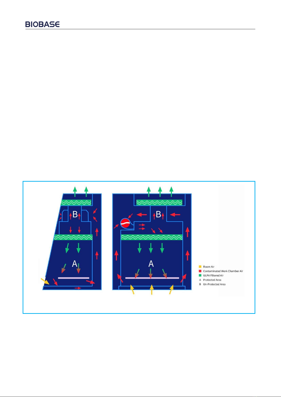
4.1.3 Working theory/Air flow pattern and protected area
Picture9
4.1.4 Protected objects
Microbiological Safety Cabinets (BSCs) are designed to protect the operator, the laboratory
environment and work materials from exposure to infectious aerosols and splashes that may be
generated when manipulating materials containing infectious agents, such as primary cultures, stocks
and diagnostic specimens.

17
4.1.5 Technical parameters
Parameters
Model
BSC-3FA2-HA
Power Supply
(230V±10%);50Hz
External
Size(W*D*H)
1087*800*2260(mm)
Working Zone
Size(W*D*H)
980*600*650(mm)
Rated power
1100 W
Total Airflow
Volume
370 m3/h
Downflow Velocity
0.33 m/s
Inflow Velocity
0.53 m/s
Fluorescent lamp
Consumption
12W*2
UV Lamp
Consumption
20W
ULPA Filter
99.9995%(Diameter:0.12μm)
Noise
≤65dB(A)
Socket
230V * 3.0A(1)
Notes :(1) Electric consumption power including two powers which operation area needs to load,the
total load power is 230V * 3.0A.
(2) The Company reserves the right to change the design of product, we will change design of
product without prior notice.
4.1.6 Performance Index
1) Biological safety functions
Personnel protection, tested by potassium iodide (KI) method, the protection factor of the front
window operation port should not be less than 1×10⁵;
Sample protection, microbial colony count ≤5CFU;
Cross contamination protection, microbial colony count ≤2CFU.
2) Leak-proof Cabinet
If cabinet pressurized to 250Pa, Paint 25 g/L of soap solution with a paint brush, without any leakage
of soap bubbles.
3) Integrity of ULPA Filter

18
Scan and detect the ULPA filter, the leakage rate at any point should not be >0.01%.
4) Vibration amplitude
The net vibration amplitude between frequency 20Hz and 2000Hz is no more than 5μm (rms).
5) Illumination
The work surface illumination is no less than 750 lux.
6) Electrical properties
Basic insulation: between live parts and the metal shell in the AC voltage 1500V, continuous 1min
without breakdown.
Reinforced insulation: between live parts and non-metallic shell in the AC voltage 3000V, continuous
1min without breakdown.
Leakage current ≤10mA.
Grounding resistance ≤0.1Ω
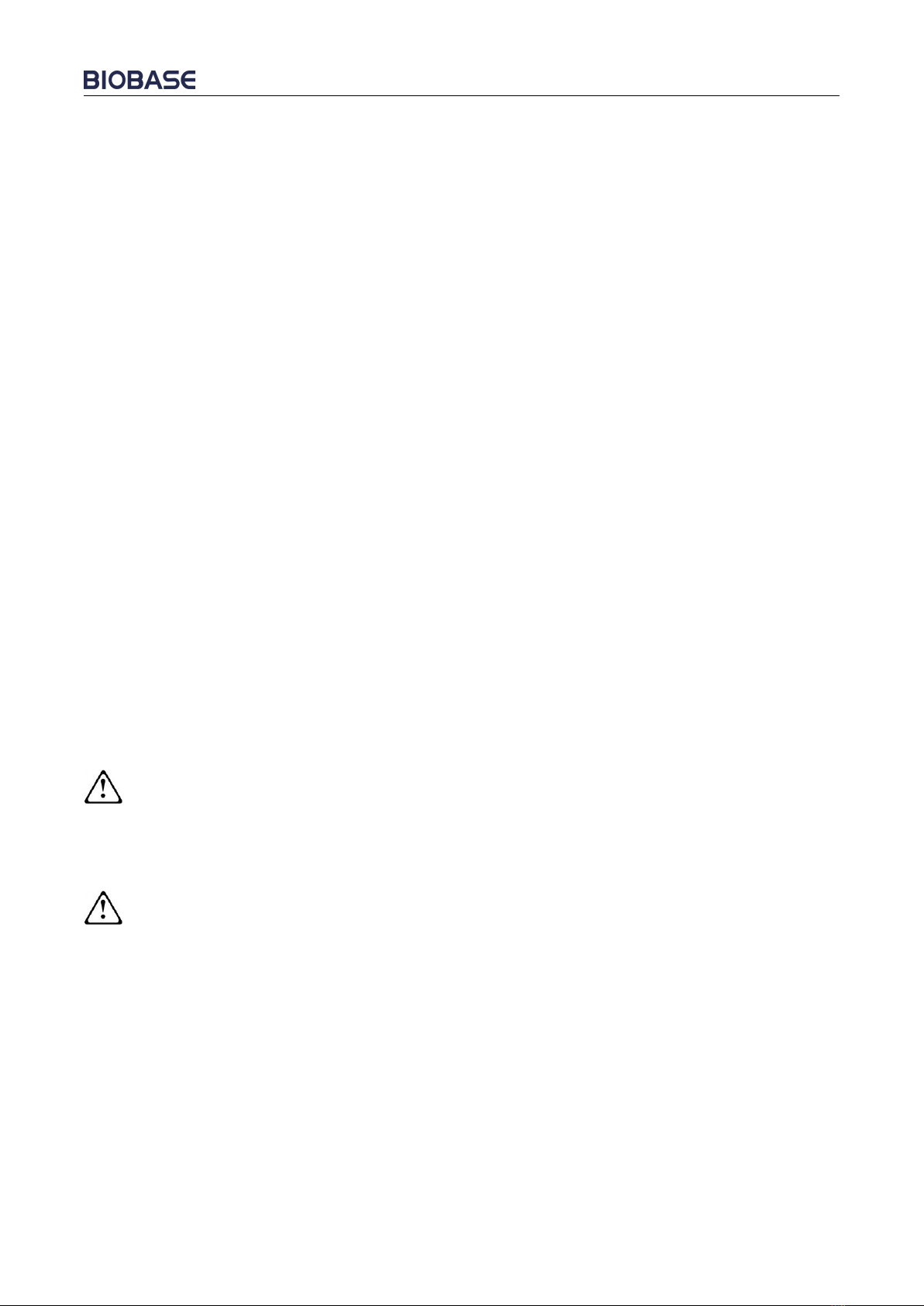
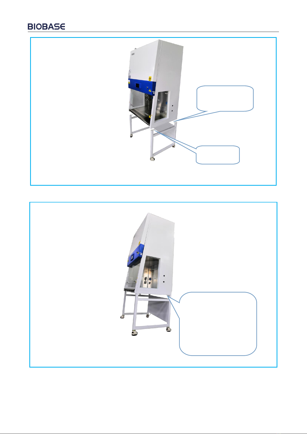
4.2 Product structure
4.2.1 Structural composition of BSC-3FA2-HA
Picture10
1
Fuma caster
2
Alarm rest plate
3
Air intake grid
4
Door glass
5
LCD display
6
Power lock
7
Fluorescent lamp
8
UV lamp
9
Side window
glass
10
Waterproof socket
11
Stepper motor
12
Counterweight
plate
4.2.2 Structure introduction
1) Driving System of Front Window
The glass door drive system consists of stepping motor(Optional), front glass door, traction
mechanism, counterweight, limit switch and so on.
2) Air Filtration System
Air Filtration System is the most important system of BSC. It consists of blower, supply filter and
exhaust filter. The function of Air Filtration System is transferring filtered air to work area, ensure
Table of contents
Other Biobase Laboratory Equipment manuals

Biobase
Biobase BK-DH2000 User manual

Biobase
Biobase BBS-H1300 User manual

Biobase
Biobase BBS-V1300 User manual

Biobase
Biobase BOV-V30F User manual

Biobase
Biobase BCI-I User manual

Biobase
Biobase BK-AutoHS96 User manual

Biobase
Biobase BK-HS32 User manual

Biobase
Biobase BSC-3FA2-NA User manual

Biobase
Biobase BSC-2FA2-HA User manual

Biobase
Biobase BKQ-B Series User manual


Popular Laboratory Equipment manuals by other brands

Fisher Scientific
Fisher Scientific Fisherbrand 88861027 Operation manual

Prestige medical
Prestige medical Classic Media 210047 user manual

Bruker
Bruker Ascend 400'89 user manual

Anderson
Anderson FHA97 Operation manual

Infors HT
Infors HT Multitron operating manual

TSI Instruments
TSI Instruments 3082 Operation and service manual


