Biobase BBS-DDC User manual

Vertical Laminar Flow Cabinet
BBS-DDC /BBS-SDC /BBS-DSC /BBS-SSC
User Manual
BIOBASE GROUP
Version 2022.01

1
Preface
Thank you very much for purchasing our Vertical Type Laminar Flow Cabinet Model
BBS-DDC/SDC/DSC/SSC.
Please read the “Operating Instructions” and “Warranty” carefully before operating this unit to assure
proper operation. After reading these documents, be sure to store them securely together with the
“Warranty” within reach for future reference.
Warning: Before operating the unit, be sure to read carefully and fully understand important
warnings in the operating instructions.

2
Content
Preface.................................................................................................................................................... 1
Content................................................................................................................................................... 2
1. Unpacking, Installation and Debugging.............................................................................................4
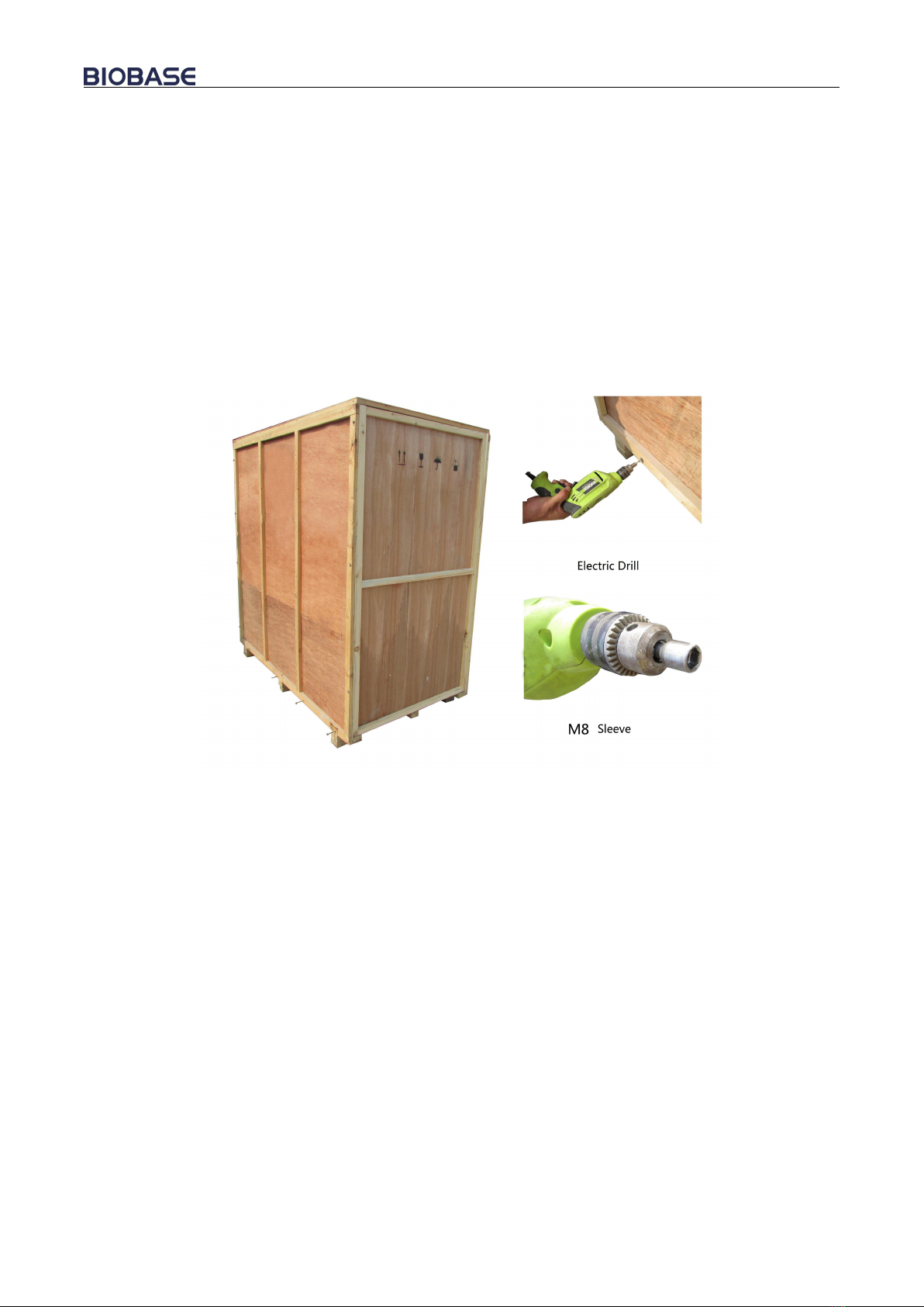
1.1 Unpacking................................................................................................................................. 4
1.2 Accessories Checking................................................................................................................6
1.3 Installation Conditions and Operating Environment.................................................................8
1.4 Installation................................................................................................................................. 9
1.5 Inspection after Installation..................................................................................................... 13
2. User Instructions...............................................................................................................................14
2.1 Functions................................................................................................................................. 14
2.1.1 Product Concept............................................................................................................ 14
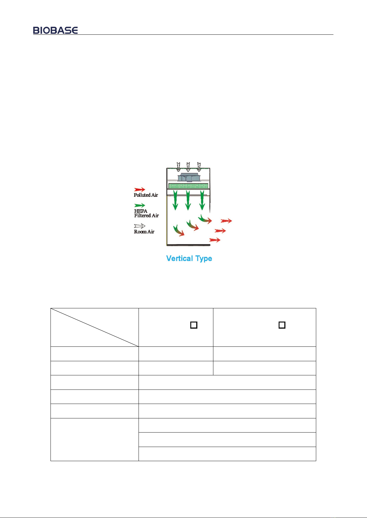
2.1.2 Operating Principle/Air flow Pattern (Picture 7).......................................................... 14
2.1.3 Protected Object............................................................................................................ 14
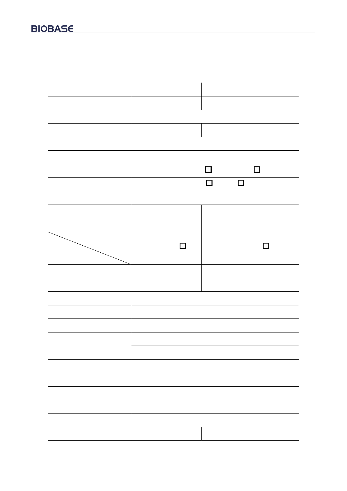
2.1.4Technical Parameters..................................................................................................... 14
1) Vibration Amplitude................................................................................................................. 16
2) Illumination...............................................................................................................................16
3) Electrical Characteristic............................................................................................................ 16
2.2 Product Structure.....................................................................................................................17
2.2.1 Structural Composition of BBS-DDC/BBS-SDC (Picture 8)....................................... 17
2.2.2 Structural composition of BBS-DSC/BBS-SSC (Picture 9)......................................... 18
2.2.3 Structure Introduction....................................................................................................18
2.3 Instructions for Operation....................................................................................................... 20
2.3.1 Normal Operation Notice.............................................................................................. 20
2.3.2 Operation Process..........................................................................................................20
2.4 Daily Maintenance.................................................................................................................. 21
2.4.1 Clean the operating area surface................................................................................... 21
2.4.2 Clean the external surface and front window................................................................21
2.4.3 Comprehensive maintenance period............................................................................. 21

3
2.4.4 Maintenance methods....................................................................................................21
2.4.5 Storage conditions......................................................................................................... 22
2.5 Replacement parts list(For parts purchase)............................................................................. 22
2.6 Wiring Diagram (Picture 12)...................................................................................................24
3. Trouble Shooting and Solution.........................................................................................................25
3.1 Common faults and solution....................................................................................................25
3.2 Replacement of Fuse............................................................................................................... 26
3.3 Replacement of LED Lamp.....................................................................................................27
3.4 Replacement of UV Lamp.......................................................................................................27
3.5 Label Description.................................................................................................................... 28
4. Warranty...........................................................................................................................................28

4
1. Unpacking, Installation and Debugging
Please firstly check if the packing box is in good condition. If the packing box is damaged, please
take photos.
1.1 Unpacking
Choose proper tools and unpacking method as shown in the below picture.
For wooden box:
1) Method 1 Necessary tools for unpacking: Electric drill with hexagon dead M8
Picture 1

5
2) Method 2 Use M8 Wrench to unpack
Picture 2
The following diagram demonstrates quick unpacking procedures (Picture 3). Remove the screws as
shown in the below diagram, then remove the wooden sheet to right and left of the wooden box.
Picture 3
For carton box:
Using scissor to cut the packing tape, take off the package cover, then move up the box body.

6
Picture 4
1.2 Accessories Checking
Refer to the packing list and check the accessories.
BBS-DDC Packing list
Items
Position
Quantity
Main body
Inside the packing box
1 unit
Base stand
Paper package(behind the cabinet)
1 pc
Power cord
Packing bag(behind the cabinet)
1 pc
Fuse protector(10A)
Packing bag(behind the cabinet)
1 pc
UV Lamp(T6 18W)
Paper package(behind the cabinet)
1 pc
User Manual
Paper package(behind the cabinet)
1set
Inspection report
Paper package(behind the cabinet)
1 pc
Certificate of quality
Paper package(behind the cabinet)
1 pc
Warranty card
Paper package(behind the cabinet)
1 pc
Hexagon socket head cap screws
M10×55
Paper package(behind the cabinet)
3sets
flat washer 10 + spring washer 10
Paper package(behind the cabinet)
3 sets

7
Hexagon wrench
Paper package(behind the cabinet
1 set
BBS-SDC Packing list
Items
Position
Quantity
Main body
Inside the packing box
1 unit
Base stand
Paper package(behind the cabinet)
1 pc
Power cord
Packing bag(behind the cabinet)
1 pc
Fuse protector(10A)
Packing bag(behind the cabinet)
1 pc
UV Lamp(T6 30W)
Paper package(behind the cabinet)
1 pc
User Manual
Paper package(behind the cabinet)
1set
Inspection report
Paper package(behind the cabinet)
1 pc
Certificate of quality
Paper package(behind the cabinet)
1 pc
Warranty card
Paper package(behind the cabinet)
1 pc
Hexagon socket head cap screws
M10×55
Paper package(behind the cabinet)
3 sets
flat washer 10 + spring washer 10
Paper package(behind the cabinet)
3 sets
Hexagon wrench
Paper package(behind the cabinet
1 set
BBS-DSC Packing list
Items
Position
Quantity
Main body
Inside the packing box
1 unit
Base stand
Paper package(behind the cabinet)
1 pc
Power cord
Packing bag(behind the cabinet)
1 pc
Fuse protector(10A)
Packing bag(behind the cabinet)
1 pc
UV Lamp(T6 18W)
Paper package(behind the cabinet)
1 pc
User Manual
Paper package(behind the cabinet)
1set
Inspection report
Paper package(behind the cabinet)
1 pc
Certificate of quality
Paper package(behind the cabinet)
1 pc
Warranty card
Paper package(behind the cabinet)
1 pc

8
Hexagon socket head cap screws
M10×55
Paper package(behind the cabinet)
5sets
flat washer 10 + spring washer 10
Paper package(behind the cabinet)
5sets
Hexagon wrench
Paper package(behind the cabinet
1 set
BBS-SSC Packing list
Items
Position
Quantity
Main body
Inside the packing box
1 unit
Base stand
Paper package(behind the cabinet)
1 pc
Power cord
Packing bag(behind the cabinet)
1 pc
Fuse protector(10A)
Packing bag(behind the cabinet)
1 pc
UV Lamp(T6 30W)
Paper package(behind the cabinet)
1 pc
User Manual
Paper package(behind the cabinet)
1set
Inspection report
Paper package(behind the cabinet)
1 pc
Certificate of quality
Paper package(behind the cabinet)
1 pc
Warranty card
Paper package(behind the cabinet)
1 pc
Hexagon socket head cap screws
M10×55
Paper package(behind the cabinet)
5 sets
flat washer 10 + spring washer 10
Paper package(behind the cabinet)
5 sets
Hexagon wrench
Paper package(behind the cabinet
1 set
1.3 Installation Conditions and Operating Environment
Laminar flow cabinet should be placed in a position where the airflow can be protected.
Laminar flow cabinet should not be installed opposite to door or window and far away from the air
outlet of air conditioner. It should avoid airflow influence from ventilating system, air conditioner,
door, window and movement of people.
At least 300mm gap must be kept in the side and back side of the Laminar Air Flow for clean
operating and for inspection.
Working environment:
(1) Only applicable to indoor operation;
(2) Ambient temperature: 15℃~35℃;
(3) Relative Humidity: ≤75%;
(4) Atmospheric pressure range: 70 kPa~106 kPa;
(5) Electrical parameters: Adequate power supply to the Laminar flow cabinet (See 2.1.4 Technical

9
Parameters );
(6) Power supply need to be grounded; (Judging method: test the live wire and the neutral wire of the
socket with multimeter. The voltage between live and ground should equal to the voltage of local
electrical grid, and the voltage between neutral and ground should equal to 0. Otherwise the
power supply is not grounded correctly);
1.4 Installation
a. Remove all the packing materials;
b. Check for Physical damage or scratch the surface of main body during transit. Make sure there
is no damage, scratch, deformation or foreign bodies;
c. Carefully check the accessories and material according to packing list in the manual.
d. Before breaking the package, move the entire equipment to the place where it is going to be
installed.
NOTE: Direct installation is completed for base stand part at the time of transport or it is
put at the back of the laminar flow cabinet. Base stand should be taken out before installing:
When carrying the laminar flow cabinet, top-for-bottom, dumping place and dismantling are
forbidden.

10
e. Assemble the base stand (if have) referring to Picture 5.
BBS-DDC/BBS-SDC base stand
BBS-DSC/BBS-SSC base stand
Picture 5
Removing Hexagon cylinder head bolt on both side lateral brace and T frame, the bottom of T frame,
assemble referring to the picture, fasten the screw and Cap nut on the both side of base stand.
Foot height can be adjusted. Clockwise rotation of feet, when feet height is less than casters, the
cabinet can be (or base stand) moved; anticlockwise rotation of feet, when feet height is greater than
casters, then play a fixed role in preventing the cabinet (or base stand) from moving.
NOTE: If there are any questions, please contact the Engineer for process debugging
f. Connect base stand with main body
Please connect the base stand with the main body referring to Picture 6.

11
(a).BBS-DDC/BBS-SDC
Hexagon socket head screws
M10×55/Flat washers 10/Washers
10
Positioning
bolt for
installing
cabinet

12
(b).BBS-DSC/BBS-SSC
Place the cabinet in the base stand, as shown in Picture 6, The base of the cabinet to install the
positioning bolt alignment on the cabinet on the left and right side of the bottom of the installation
hole, using M10 × 55 Inner six angle cylinder head bolt, flat washers 10 and spring washers 10
bottom up through the base stand and side plate and fastened firmly.
g. After the above steps, slightly moving the cabinet to the proper position, remove the power line,
power line inspection is intact.
Positioning
bolt for
installing
cabinet
Hexagon socket head screws M10×55/Flat
washers 10/Washers 10

13
1.5 Inspection after Installation
First, check the electrical power supply, make sure the voltage and frequency match with the
Instrument power supply rating, then check the follows items with power on:
Checking Items
Normal working status
Fan
Runs normally
LED Lamp
Lamp lights up after pressing button
UV Lamp
Lamp lights up after pressing button
Screen Buttons
All buttons work effectively
NOTE: If there is any problem, please contact the engineer for process debugging.
Debugging methods is in the after-sales service manual.

14
2. User Instructions
2.1 Functions
2.1.1 Product Concept
Laminar Flow Cabinet –LAF Cabinet is only for sample protection.
Laminar Flow Cabinet is a work bench or similar enclosure, which creates a particle-free working
environment by taking air through a filtration system and exhausting it across a work surface in a
laminar or unidirectional air stream. The laminar flow cabinet is enclosed on the sides and kept under
constant positive pressure in order to prevent the infiltration of contaminated room air. This model is
vertical laminar flow cabinet.
2.1.2 Operating Principle/Air flow Pattern (Picture 7)
Picture 7 Air flow pattern
2.1.3 Protected Object
Sample protection only
2.1.4Technical Parameters
Model
Parameters
BBS-DDC
BBS-SDC
External Size (W*D*H)
1040×615×1770 mm
1440×615×1770 mm
Working Zone Size
(W*D*H)
940×540×545 mm
1340×540×545 mm
Work Surface Height
750mm
Display
LED Display
Airflow Velocity
Average of 0.3~0.5m/s
Material
Main Body: Cold-rolled steel with anti-bacteria powder c
oating
Work Table:304 stainless steel
Side Windows:5mm toughened glass, anti-UV

15
Pre-filter
Polyester fiber, washable
HEPA Filter
99.999% efficiency at 0.3um
Noise
<65dB
LED Lamp
12W*1(LED)
16W*1(LED)
UV Lamp
18W*1
30W*1
Emission of 253.7 nanometers
Consumption
≤350W
≤600W
Waterproof socket
Two, total load≤500W
Caster
Universal caster with leveling feet
Power Supply AC
220V±10% 110V±10%
Frequency
50 Hz 60Hz
Standard Accessory
LED lamp, UV lamp*2,Base stand, Waterproof socket*2
Gross Weight
150kg
174kg
Package Size(W*D*H)
1190*890*1340mm
1590*890*1330mm
Model
Parameters
BBS-DSC
BBS-SSC
External Size (W*D*H)
1040×660×1770 mm
1440×660×1770 mm
Working Zone Size
(W*D*H)
940×560×545 mm
1340×560×545 mm
Work Surface Height
750mm
Display
LED Display
Airflow Velocity
Average of 0.3~0.5m/s
Material
Main Body: Cold-rolled steel with anti-bacteria powder c
oating
Work Table:304 stainless steel
Pre-filter
Polyester fiber, washable
HEPA Filter
99.999% efficiency at 0.3um
Noise
<65dB
Front Window
Manual, 5mm toughened glass, anti-UV
Max Opening
350mm
LED Lamp
12W*1(LED)
16W*1(LED)

16
UV Lamp
18W*1
30W*1
Emission of 253.7 nanometers
Consumption
350W
600W
Waterproof socket
Two, total load≤500W
Caster
Universal caster with leveling feet
Power Supply AC
220V±10% 110V±10%
Frequency
50 Hz 60Hz
Standard Accessory
LED lamp, UV lamp*2,Base stand
Gross Weight
150kg
174kg
Package Size(W*D*H)
1190*890*1340mm
1590*890*1340mm
NOTE: the company reserves all the rights to changes in product design, if there are any
design change, we will not inform in advance.
1) Vibration Amplitude
The net vibration amplitude between 10Hz and 10KHz is less than 5μm (rms).
2) Illumination
Average illumination is not less than 350 lx.
3) Electrical Characteristic
- The voltage increases to 1390V (AC) in 5s and keep for another 5s without breakdown.
- Ground resistance≤0.1Ω

17
2.2 Product Structure
2.2.1 Structural Composition of BBS-DDC/BBS-SDC (Picture 8)
1.Control Panel 2. Power Socket
3.UV Lamp 4. LED Lamp
5. Front Window 6. Handle
7.Work Table 8. Base Stand
9. Leveling Feet 10. Caster
Picture 8
4
1
7
9
10
8
6
5
3
2

18
2.2.2 Structural composition of BBS-DSC/BBS-SSC (Picture 9)
1. Control Panel 2. Power Socket
3. UV Lamp 4. LED Lamp
5. Front Window 6. Door knob
7.Work Table 8. Base Stand
9. Caster 10. Leveling Feet
Picture 9
2.2.3 Structure Introduction
1) Driving system of front window
Driving system consists of constant force spring and front window.
2) Air filtration system
Air filtration is the core system of laminar flow cabinet. It consists of blower and filter. The main
function of air filtration system is to transfer filtered air to work area, ensure the flow velocity, and
keep cleanness of work area.
3) UV lamp
The UV lamp located at the top of the work zone effectively disinfects the entire work zone by
emitting a wavelength of 253.7nm
4) LED lamp
Laminar flow cabinet is equipped with energy-saving LED LED lamp, which ensures the standard
requirement of average illumination is met
5) Control panel (Picture 10)
4
5
10
1
2
3
6
7
8
9

19
Picture 10
1.Gear Indicator 2.Increase Air Velocity
3.Decrease Air Velocity 4. Fan indicator
5.Fans 6.UV Indicator
7.UV 8.Light Indicator
9.Light
a) Gear indicator
To see air speed gears of the equipment through gears indicator.
b) Soft touch buttons
Main functions all could be executed either by touch pressing.
: To control lamp
: To control UV lamp. UV lamp, fans and LED lamp are interlocked. UV lamp will
automatically turn off when open the fans or LED lamp.
: To control blower during working
Air velocity control ( ): During working, button to increase air velocity; button
to decrease air velocity.
6) Fuse protector
The cabinet is equipped with main power fuse. For double-pane window, it is located beside the
power cord’s outlet. For single glass, they are both located at the back of the power cord’s outlet.
Fuse label is corresponding to the relevant specifications. Please refer to 3.5.1 and picture 3.2 when
changing fuse protector.
7) Control of front window
Front window is controlled by constant force spring. It can be stably stopped at any height during
allowed height. It still can be controlled and take out samples inside when power off.
8) Structure
This manual suits for next models
3
Table of contents
Other Biobase Laboratory Equipment manuals

Biobase
Biobase BFG Series User manual

Biobase
Biobase BSC-4FA2-GL User manual

Biobase
Biobase BBS-H1300 User manual

Biobase
Biobase BSC-4FA2-HA User manual

Biobase
Biobase LC-4KC User manual

Biobase
Biobase BCBL-207 User manual

Biobase
Biobase BSC-3FA2-NA User manual

Biobase
Biobase BBS-V800 User manual

Biobase
Biobase BKQ-B Series User manual

Biobase
Biobase BOV-V30F User manual