Biobase LC-4KC User manual

Table-top Low Speed Centrifuge
LC-4KC / LC-4KII
User Manual
BIOBASE GROUP
Version 2020.11

1
Content
1. GENERAL......................................................................................................................................... 2
2. PECULIARITY..................................................................................................................................2
3. PRINCIPLE OF OPERATION.......................................................................................................... 2
4. SPECIFICATION.............................................................................................................................. 3
5. PARTS IDENTIFICATION...............................................................................................................3
6. USING CONDITIONS...................................................................................................................... 3
7. OPERATION PROCEDURE.............................................................................................................3
8. MAINTAIN........................................................................................................................................4
9.GUARANTEE.....................................................................................................................................5
10. COMMON TROUBLE &RESOLUTION................................................................................... 5
11. CIRCUIT DIAGRAM......................................................................................................................6

2
1. GENERAL
The frame of this instrument is made of high strength plastic.Its model is beautiful, and it has the
advantages of small cubage, low weight, large capacity, low noise, high efficiency and so on.
It can be used in hospitals and biochemical labs for qualitative analysis of serum, urea and plasma.
2. PECULIARITY
2.1 Rotor imbalance protection device.
2.2 Speed choice in advance &acceleration accurate gradually.
2.3 Door switch and mechanical safety lock.
3. PRINCIPLE OF OPERATION
Put tubes with sample that can be balance into a angle rotor symmetrically, the rotor will spin on axis
after you start the machine, and the relative centrifuge force (RCF) comes into being while rotating,
It will make the composition at different weight density separate from solution.
The formula of calculating RCF is as follows:
RCF=1.118×10⁻⁵n2r
n-------- rotating speed
r-------- radius of rotating
The formula of calculating separation time is as follows:
ρ-------- density of mixed liquid (g/cm3)
μ-------- glutinousness of mixed liquid (p)
n-------- rotating speed
r-------- radius of particle (cm)
Q------- density of particle (g/cm3)
Rmax-------- The horizontal distance from the bottom of solution to the center of the rotating axis
(cm)
Rmin-------- The horizontal distance from the surface of solution to the center of the rotating axis
(cm)

3
4. SPECIFICATION
Max. speed: 4000r/min
Max. RCF: 2325×g
Capacity: 12×20ml
Time range: 0-99 min
Power source: 220V 50Hz
Power supply: 135W
Dimension: 280×310×265 ( L*W*H )mm
Net weight: 10Kg
Noise: <70dB
5. PARTS IDENTIFICATION
1. Control panel 2. Frame work 3. Damping system 4. Cover 5. Rotor 6.Nut 7. Motor
8. Toroidal transformer 9.Electric controlling system 10.Centrifugal chamber 11.Rubber foot
PS: there are two buttons on the right side.
The green button is power button and another one is safety lock.
6. USING CONDITIONS
6.1 Ambient temperature: 0~30℃
6.2 Relative moisture: <80%
6.3 No electro conductive dust, explosive and corrosive gas in the surrounding air.
7. OPERATION PROCEDURE
7.1 Control panel (see the following fig )

4
1. Speed display 2. Time display 3. Power ON
4. Power indicator 5. Power OFF
7.2 Preparation
①Put the centrifuge on a steady table, and the centrifuge must be 10cm distance from the wall.
②Set tubes with sample that can be balance, and put them into holes within the rotor.
7.3 Operation Steps:
①Shut the cover, connect the power. Press the power button on the right first, then press “speed”
key to set your needed speed; press “time” key to set your needed time.
②Turn on the power ON, the machine starts to run, at this time, time starts reckon by time when the
speed up to your setting speed; when time up to your setting time, machine stop running.
If the machine is working, do not open the cover.
③Turn off power OFF, press the safety lock and take out test tubes.
8. MAINTAIN
8.1 Please read the manual book before operation.
8.2 If you found test tubes were aging or corroded before using it, please replace them in time.
8.3 The power should have reliable grounding.
8.4 The test tube must be set with sample that can be balance and put into the rotor symmetrically so
as to keep balance.
8.5 You should cut off the power as soon as hearing abnormal noise.
8.6 Don’t remove the machine while it is running.
8.7 Don’t put any goods on the machine cover.
8.8 If the sample density is more than 1.2 g/cm3, you must calculate Max. speed(N) in the following
formula:
Nmax-------- the limit speed
ρ -------- sample density

5
9.GUARANTEE
Six month.
10. COMMON TROUBLE &RESOLUTION
No.
Common trouble
Reason
Solution
1
Connect the power,
but the indicator
and nixie tube don’t
light
No 220V power
Check the power
Blown fuse
Replace
Power switch
doesn’t turn on
Turn on power
switch
2
Set speed with
actual speed
are different
Voltage is on the
high side or low
side
Contact with
electric
department
3
Door locker can not
lock during run.
Door lock
Check and
Replace
4
There is noise after
starting on the
machine
Tube with
liquid not
equaling sample
or rotor nut
loosen
Make the tube
with equaling
sample,
tighten the nut
5
Machine didn’t
work according to
adjusted value
Forget to press
Ok key to
confirm
Reset value you
needed and
press Ok key to
confirm
6
Time/Trouble
window show
E3
Door switch
damaged or not
closed well
Press cover or
replace
E4
Cover is open
during running.
Closed the
cover ,and start
up again
E5
Locked
driven
damaged
rotor,
plate
Replace motor
or driven plate.

6
11. CIRCUIT DIAGRAM

BIOBASE GROUP
2# building, No.9 Gangxing Road, High-tech Zone, Jinan City, Shandong Province,
China
Tel: +86-531-81219803/01
Fax: +86-531-81219804
Inquiry: expo[email protected]
Complaints: customer_support@biobase.cc
After-sales service: service_sd@biobase.cc; service_ivd@biobase.cc
Web: www.biobase.cc/www.meihuatrade.com / www.biobase.com

Table-type Low Speed Centrifuge
BKC-TL4 / BKC-TL4II / BKC-TL4III
User Manual
BIOBASE GROUP
Version 2020.09

1
Content
1. The name and model of the product.................................................................................................. 2
2. Features and applications.................................................................................................................. 2
3. The operation principles.................................................................................................................... 3
4. Technical parameters......................................................................................................................... 4
5.The rotor parameters.......................................................................................................................... 4
6. The operation procedures.................................................................................................................. 4
7. Safety Notice................................................................................................................................... 10
8. Warranty Service Instruction........................................................................................................... 11
9. Comment Malfunctions and Obviating Methods............................................................................ 11
10. Transportation and storage of the machine....................................................................................12
11. Unpacking and examination of the machine................................................................................. 12

2
1. The name and model of the product
Table-type low speed centrifuge, model BKC-TL4II.
2. Features and applications
Table-type low speed centrifuge, model BKC-TL4II.(This machine below is short for this centrifuge
machine.),The series centrifuge is widely applied in biology, chemistry, medicine, agriculture and
forest science, food safety, blood station and clinical test.
This machine features good rigidity, high strength and corrosion proofing, owing to its high material
of steel and its surface with spurt models processing. Meanwhile, this machine possesses the
advantages of succinct structure, small volume, low noise, smooth temperature rise, high efficiency,
safe and reliable, and it is fit for the experimental analysis with fewer samples and more separation
steps.
This machine adopts the advanced technologies like microcomputer control, direct drive brushless
DC motor, TFT Zhencai touch panel, mute mechatronics electronic lock and so on.
The features of this machine are as followed:
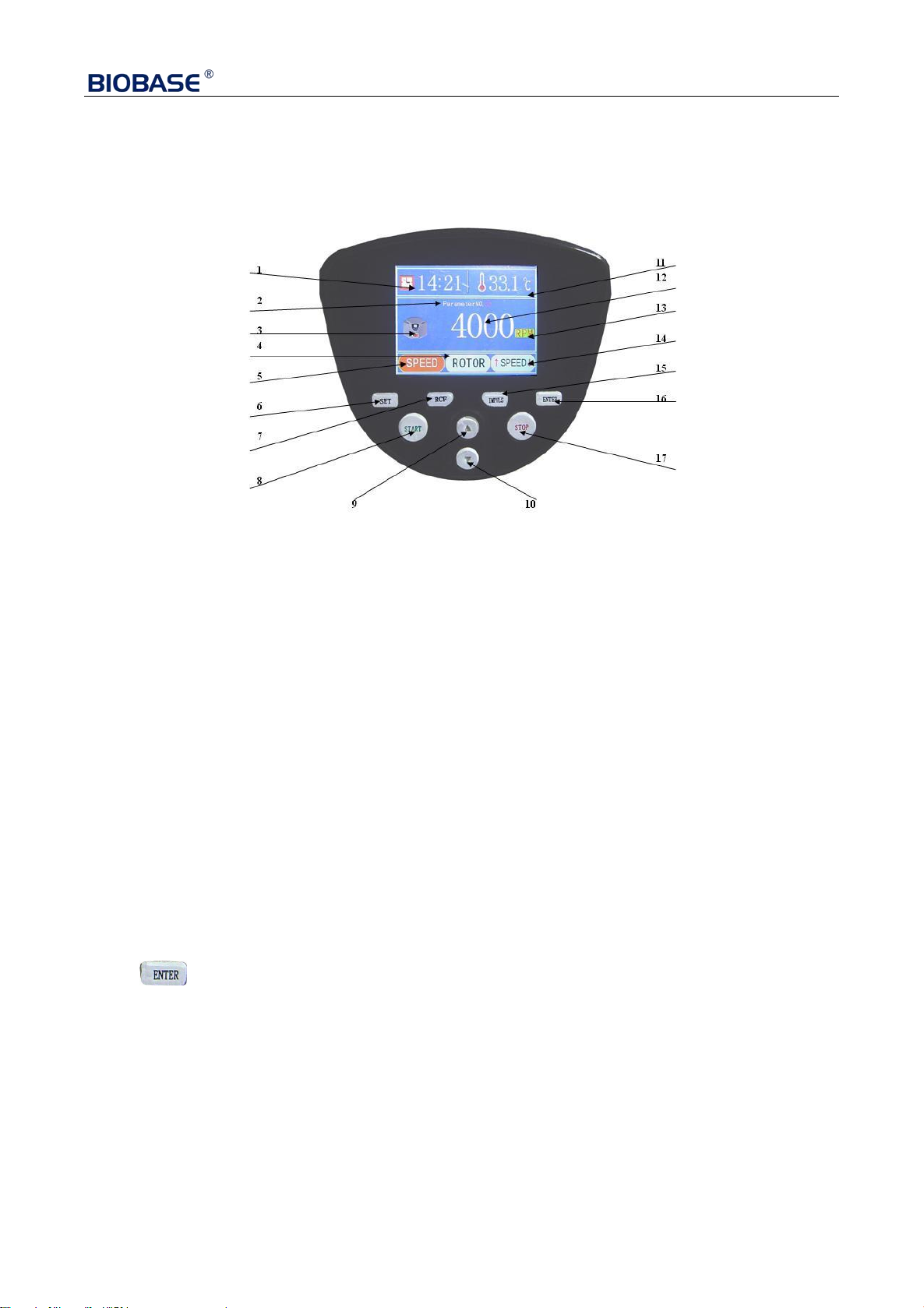
Step 1: Set up the rotor mode, the rotating speed and the needed time.
The vibration-absorption effect of this machine works very well by the application of its special
damper. This machine also has a self-balance function.
Step 2: Set up the rotor mode, the rotating speed and the needed time.
The special PWM-controlled speed control system assures its high control accuracy and its fast
acceleration and deceleration function, which provides different acceleration and deceleration time
to be freely chosen. To meet the requirement of labs, the brushless DC motor also assures the
operation of the machine in a quiet working state. The carbon brush doesn’t need to be replaced, so
there are no carbon pollutions.
Step 3: Set up the rotor mode, the rotating speed and the needed time.
This machine has a parameter-saving function, and it can calculate the RCF value automatically.
Step 4: Set up the rotor mode, the rotating speed and the needed time.
There are many rotors with different levels. The tube frame can be replaced, and there are many
tubes, convenient to choose.
Step 5: Set up the rotor mode, the rotating speed and the needed time.
This machine has a protective function owing to its electronic lock. When its faceplate is uncovered,
the centrifuge machine cannot be operated.
This machine can be safely operated in the environment with the temperature within 5 to 40
centigrade, under RH<80%, and without conducting dust, explosive gas and corrosive gas.

3
3. The operation principles
The centrifuge machine helps to separate, condense or purify the different density components (or
particles) of the solutions by the usage of centrifugal sedimentation principal.
After placing the centrifuge tubes with equivalent test solutions in the test tubes around the rotors
symmetrically and starting the machine, the RCF produced in the high-speed rotary of the rotors,
which are driven by the motor, separates the different density components (or particles) in the test
solutions. The value of RCF depends on the rotating radius “r” (the horizontal distance from the
position of the test solutions to the axle center) and the rotating speed “n”, and here is the calculation
formula.
RCF=1.118×10⁻⁶n2r×g
n------------ The rotating speed (r/min)
r------------The rotating radius (mm)
The time (Ts) needed during the separation and deposition of the mixed solutions is calculated by
this formula:
Ts =27.4×(logeRmax-logeRmin)μ
min
n2r2(б-ρ)
Type: Rmax------The rotating radius of the test solutions having the farthest distance with the
axle center
Rmin------The rotating radius of the test solutions having the nearest distance with the
axle center
ρ------The density of the mixed solutions (g/cm3)
μ------ The viscosity of the mixed solutions (p)
n ------ The rotating speed (r/min)
r------The particle’s radius (cm)
б------The particle’s density (g/cm3)

4
4. Technical parameters
Maximum rotate speed
4000r/min
Maximum centrifugal force
2600×g
Maximum capacity
24X10ml/12x20ml
Time range
0~99h59min
Rotate speed precision
±30r/ min
Noise
≤60dB
Power
AC 220V 60HZ
Dimension(L×W×H)
500×450×280mm
Weight
20kg
5.The rotor parameters
Model
Product name
Maximum
capacity
Maximum
rotate
speed(r/min)
Maximum
centrifugal force(×g)
BKC-TL4II
Centrifuge
4000
2600
No.1
Angle rotor
12×20ml
4000
2600
6. The operation procedures
Step 1: Place the centrifuge machine on the platform and ensure its balance. Shake the machine with
hands to check out whether the machine has been placed stably or not.
Step 2: Plug the supply cord into the outlet and press down the power switch (the power switch is on
the left bottom of the machine).
Step 3: After pressing down the button of “ STOP & OPEN”, put the rotors on the motor shaft,
and connect the rotors with motorshaft tightly together by tightening the screw nuts (the move should
be verygentle and substantially shaking and pressing should be avoided, so as to protectthe flexible
support system of the motor. Then, place the adapter with testtubes on the rotors and rotate the rotors.
The rotors should be turnedflexibly, the adapter should be rotated freely, and there should be no
block orcollision.
Step 4: Place the centrifuge tubes into the test tubes. The centrifuge tubes should be placed
symmetrically, and the test solutions in the tubes should be even, so as to make sure the
equilibrium operation of the machine.

5
Step 5: Cover the faceplate and check out whether it is covered tightly, or the centrifuge machine
cannot be operated.
Step 6: Set up the rotor mode, the rotating speed and the needed time
The control panel of the machine is as shown below.
The diagram of the control panel.
1.:The operation and time setting area.
2.:
The display area of the parameter numbers.
3.:The operation icon.
4.:The setting of rotor modes.
5.:The setting of rotating speed.
6.:The “SET” button.
7.:The “RCF” button.
8.:The “START” button.
9.:The “UP” button.
10.:The “DOWN” button.
11.:The temperature setting and display area.
(This is the cavity temperature, and non-refrigerated centrifuge has no such setting function.)
12.:The display area of rotating speed and centrifugal force.
13.:The shift button of rotating speed and centrifugal force.
14.:The area of acceleration and deceleration
15.: The “Impulse” button
16.: The “Enter” button
17.:The “STOP & OPEN”button

6
1)The display panel of the startup
Press the “ UP” or “ DOWN” button to choose the proper parameter set.
Attention: There are 20 sets of parameter set ranging from 00 to 19.
As it is shown below:
2)Press the “SET” button to enter the first adjustment panel, or touch the screen and click the rotating
speed area to enter the same panel.
As it is shown below:
①Press UP” or “ DOWN” button to adjust the rotating speed value.
Attention: The slowest rotating speed is 100r, and the fastest is the maximum rated speed of the rotor.
50r rotating speed can be adjusted by each press. Pressing the “UP” or “DOWN”button fixedly can
adjust the speed value continuously.

7
②Press SET” button to enter the rotating speed adjustment panel. Next, press the “ UP” or
“ DOWN” button and press the “ SET” button again to enter the time adjustment area. The
needed minutes can be chosen by pressing the “ UP” or“ DOWN” button.
As it is shown below:
③Press SET” button to enter next step, and the needed hours can be chosen by pressing the
“ UP” or “ DOWN” button.
As it is shown below:
3)On the bottom of the first adjustment panel, press the “ SET” button to enter
second adjustment panel (the adjustment panel of rotor modes), or touch the screen and click the rotor
number area to enter the same panel.
As it is shown below:

8
Press the “
UP
”
or
“
DOWN” button to choose the rotor number.
Attention: Please take the real objects as the reference, and find the corresponding real rotor pictures
and rotor number.
4)Press the “SET” button to enter third adjustment panel (the adjustment panel of acceleration and
deceleration), or touch the screen and click the acceleration and deceleration area to enter the same
panel.
As it is shown below:
①Press the “ DOWN” button to adjust deceleration of the rotating speed, or touch screen and
click the icon to do the same operation. There are 10 deceleration levels: 0 is the slowest while 9 is
the fastest.
As it is shown below:

9
②Press the “ UP” button to adjust acceleration of the rotating speed, or touch
screen and click the icon to do the same operation. There are 10 acceleration levels: 0 is the slowest
while 9 is the fastest.
As it is shown below:
5)When finishing every step mentioned above, press the “ ENTER” button for about 2 seconds
to preserve the adjusted value, and then withdraw from the adjusted state.
Step7 After checking out the settings mentioned above, press the “START” button to start
operation of the machine. During the operation, the current centrifugal force can be displayed on
the window by pressing the “ RCF” button, or touching the screen and clicking the RCF icon.
Repress the button, and the rotating speed value can be displayed again.
Step8When counting down to 0, the centrifuge machine stops working automatically. During the
operation, pressing the “ STOP & OPEN” button can also stops the operation of the machine.
When the rotating speed reaches 0, the buzzer would make a buzzing sound, and the cue words
would be displayed on the window. The faceplate can be removed.
Step9 When press the “ IMPULS” button and hold for a few seconds, the rotors would start
rotation slowly; when the rotating speed reaches its fastest speed, the rotors would not accelerate the
speed any more. When relax the “ IMPULS” button, the rotors begin the deceleration until
they stop rotating. During the deceleration process, the “ IMPULS” button cannot be pressed
any longer; when the rotors stop the rotation completely,
the centrifugal process would
restart by pressing and holding the “IMPULS” button.
Step10 After the rotors stop the rotation completely, press
the “STOP & OPEN” button to
uncover the faceplate (if the faceplate could not be removed because of its high rebound force against
the seal ring on top of the centrifugal chamber, please press the faceplate slightly with one hand and

10
repress the “ STOP & OPEN” button with the other to open the faceplate), and take out the
centrifugal tubes carefully. The whole separation process is done.
Step11 Turn off the power switch, and cut off the power of the centrifugal machine.
7. Safety Notice
1.This machine should not be used in the humid places with high temperature and large fugitive
dust.
2.To ensure the safety and its centrifugal effect, this machine should be placed in the solid,
quakeproof and horizontal platform, and all four undercarriages should be given the balanced
load.
3.The solutions in the centrifugal tubes should be seen as even as possible. If the solutions in
the tubes vary too much, there would be a large scale of vibration. In this kind of situation, the
operating machine should be stopped its operation and checked to meet the requirement of the
solutions in the tubes. The centrifugal tubes should be placed symmetrically in the even
numbers, and the nut caps connecting the rotors with the motor shaft should be tightened.
4.During the operation process, the centrifugal machine cannot be moved, and the faceplate
cannot be uncovered.
5.The faceplate should not be uncovered in the situation that the motor and the rotors do not
stop the operation completely.
6.The power supply has its own earth wire, so the null line and the earth wire cannot be used
together, so as to prevent the damage of electric shock.
7.After the whole separation, the centrifuge machine should be cleaned up in time, the power
switch should be turn off, and the power supply should be cut off.
8.It should be very careful to take out the rotors. The proper way is to knock upward slightly the
rotors on the bottom by using nonmetal tools (like the handle of the screwdriver) until the
connection between the rotors and the motor shaft becomes loose. The rotors should not be
pulled out directly with hands after loosening the nut caps, so as not to damage the flexible
support system of the machine.
9.The rotors ad the centrifugal tubes should be checked regularly. If there are any cracks or
aging phenomena, those components should be replaced immediately.
Instruction: There is an emergency device on the bottom of the machine. If the sample
should be taken out during the power outage, the faceplate can be uncovered by pulling
the stainless wire on the bottom after the rotors stop the operation. But this device is
forbidden to be used during the operation process.

11
8. Warranty Service Instruction
The warranty period of this centrifuge machine lasts one year since its purchased day. During
the warranty period, if the machine is damaged by artificial factors, maintenance services would
be provided with some appropriate fee. After the warranty period, all repairs are billed at cost.
9. Comment Malfunctions and Obviating Methods
There is a malfunction display window. When the machine breaks down, the buzzer would make a
buzzing sound and the cue words would be displayed on the window.
1. Overheat. 2. Overspeed. 3. The faceplate uncovers.
4.If the faceplate becomes open during the operation, the machine would enter the stall mode. The
malfunction obviation or operation work should be done after the rotating speed turns back to 0.
5.If the setting goes wrong, for example, when the setting rotating speed exceeds the maximum rated
speed of the rotors, the machine would automatically run with the maximum
rated speed of the rotors.
6.If the operating temperature is too high and the cavity temperature is over 55 centigrade, the
machine cannot be operated. After its cooling, the machine goes back to work normally.
Besides the malfunctions mentioned above, please contact the technicians of the
manufacturer to obviate the malfunctions.
The obviating methods of the common malfunctions are as followed.
Common malfunctions
Causes
Obviating methods
The monitor doesn’t work
after connecting with the
power supply.
There is no 220V
power supply.
Check the power
supply.
The fuse is melted.
Change the fuse.
The machine can work but the
speed cannot be accelerated,
or the machine sounds or
smells strangely.
The control system
goes wrong.
Send the machine to
the manufacturer for
the maintenance.
The actual rotating speed is
inconsistent with the setting
or displaying rotating speed.
The machine runs unstably or
even out of control.
The control system
goes wrong.
Send the machine to
the manufacturer for
the maintenance.
This manual suits for next models
1
Table of contents
Other Biobase Laboratory Equipment manuals

Biobase
Biobase BSC-4FA2-GL User manual

Biobase
Biobase BCBL-207 User manual

Biobase
Biobase BSC-4FA2-HA User manual

Biobase
Biobase BSC-2FA2-HA User manual

Biobase
Biobase BKQ-B Series User manual

Biobase
Biobase BBS-V1300 User manual

Biobase
Biobase BBS-DDC User manual

Biobase
Biobase BK-HS32 User manual

Biobase
Biobase BBS-H1300 User manual

Biobase
Biobase BK-DH2000 User manual