bioMerieux BACT/ALERT 3D 60 User manual

Service Manual
bioMérieux, Inc.
Box 15969, Durham, NC 27704-0969
http://www.biomerieux.com
©BIOMÉRIEUX 2002 Manual Part Number 48001-6 Rev A March 2003
BB
AA
CC
T AT A
LL
EE
RR
TT
33
DD
66
00
R
TM

BacT/ALERT® 3D 60
Service Manual
All Rights Reserved Worldwide
Printed in the United States of America
No part of this publication may be used or reproduced in any form, electronic or written via database or
retrieval system, without the prior written permission of bioMérieux. Documenting copies of any part of this
publication, for any purpose other than for which has been authorized in advance, is in strict violation of
United States copyright laws.
BioMérieux, Inc.
PO Box 15969
Durham, NC 27704-0969
USA
ASTM is a trademark of American Society for Testing and Materials. BacT/ALERT, BacT/LINK, BacT/VIEW
and MB are registered trademarks of bioMérieux in the USA and other countries. MS DOS is a registered
trademark of Microsoft Corporation. Zip is a registered trademark of Iomega Corporation. The logo is a
registered and protected trademark of bioMérieux, Inc. or one of its subsidiaries.
Distribution in over 130 countries

BacT/ALERT® 3D 60
Service Manual
This document will be updated for each software modification or any other change.
Information supplied in this document is subject to modification before the products described
become available.
This document may contain information or references concerning certain bioMérieux®
products, programs and services not available in certain countries; this, however, shall not
mean that bioMérieux intends to commercialize such products, programs or services in said
countries.
To request copies of publications or for any technical request, contact bioMérieux or your
local distributor.
Liability disclaimer
bioMérieux disclaims all warranties, guarantees or liabilities, express or implied arising by law
or otherwise with respect to this manual, its quality, accuracy or performance, including
without limitation, any obligation of bioMérieux with respect to MERCHANTABILITY AND
FITNESS FOR A PARTICULAR USE, non-infringement and consequential or incidental
damages. IN NO EVENT SHALL bioMérieux’ s LIABILITY TO CUSTOMER UNDER ANY
CLAIM EXCEED A REFUND OF THE AMOUNT PAID TO bioMérieux FOR THE PRODUCT
OR SERVICE WHICH IS THE SUBJECT OF THE CLAIM.
In no event shall bioMérieux be bound by the manual. bioMérieux shall have the right to
modify the manual without notice.
bioMérieux Copyright
This manual's content and graphics are copyrighted by bioMérieux.
In no event does bioMérieux concede to the manual's users any right for reproduction,
adaptation or translation, by any process and in any country whatsoever.
All editorial content and graphics (including without limitations, all articles, text, images, logos,
compilations, designs) are protected by United States Copyright Law, French Copyright Law
and international treaties and may not be copied without the express permission of
bioMérieux.
Any representation or reproduction whether partial or integral, by any process whatsoever,
would therefore be considered fraudulent and sentenced by the applicable law.

BacT/ALERT® 3D 60
Service Manual
THIS PAGE
INTENTIONALLY
LEFT BLANK

BacT/ALERT® 3D 60 TABLE OF CONTENTS
Service Manual i
TABLE OF CONTENTS
0FRONT MATTER..................................................................................................................IX
0.1 APPENDICES.................................................................................................................IX
0.2 LIST OF TABLES...........................................................................................................XI
0.3 LIST OF ILLUSTRATIONS..........................................................................................XIII
0.4 TYPOGRAPHY AND GRAPHIC CONVENTIONS.....................................................XIX
0.4.1 Bullets..............................................................................................................xxi
0.4.2 Text Boxes .......................................................................................................xxi
0.4.3 Bracketed Italics................................................................................................xxi
0.4.4 Underlined Text.................................................................................................xxi
0.4.5 Bracketed Text.................................................................................................xxii
0.4.6 Text Within Quotation Marks.............................................................................xxii
0.4.7 Italicized (Whether Bold or Not) Text .................................................................xxii
0.5 SAFETY SUMMARY.................................................................................................XXIII
0.5.1 General Information to Follow ........................................................................... xxv
0.5.2 Electrical Warnings........................................................................................... xxv
0.5.3 Electrical Grounding .........................................................................................xxvi
0.5.4 Fuse Replacement Warning..............................................................................xxvi
0.5.5 Hazardous Voltages .........................................................................................xxvi
0.5.6 Cleaning Agents...............................................................................................xxvi
0.5.7 Health Risks ...................................................................................................xxvii
0.5.8 ESD Precautions.............................................................................................xxvii
0.5.9 Moving Parts...................................................................................................xxvii
0.5.10 Heating Element .............................................................................................xxvii

TABLE OF CONTENTS BacT/ALERT® 3D 60
ii Service Manual
1GENERAL INFORMATION..............................................................................................1-1
1.1 INTRODUCTION...........................................................................................................1-1
1.2 REFERENCE DATA.....................................................................................................1-2
1.3 EQUIPMENT DESCRIPTION.......................................................................................1-3
1.4 ASSEMBLY DESCRIPTIONS......................................................................................1-4
1.4.1 Electrical Components.......................................................................................1-4
1.4.1.1 Power Panel Assembly....................................................................1-5
1.4.1.2 Transformer Assembly.....................................................................1-5
1.4.1.3 Heater ............................................................................................1-5
1.4.1.4 Blower............................................................................................1-5
1.4.1.5 Step-5 Motor Assembly ...................................................................1-7
1.4.1.6 Fan ................................................................................................1-7
1.4.1.7 Quick Reference Card .....................................................................1-7
1.4.2 Communications Ports (Input / Output)...............................................................1-8
1.4.2.1 COMM Port.....................................................................................1-9
1.4.2.2 Printer Port .....................................................................................1-9
1.4.2.3 Internal Speaker w/external Speaker Jack ........................................1-9
1.4.2.4 Power Entry Module (PEM) / ON-OFF Switch ...................................1-9
1.4.2.5 Modem Port ....................................................................................1-9
1.4.2.6 LIS Port ..........................................................................................1-9
1.4.2.7 Monitor Port ....................................................................................1-9
1.4.2.8 UPS Port ........................................................................................1-9
1.4.2.9 UPS Serial Port...............................................................................1-9
1.4.2.10 Mouse Port .....................................................................................1-9
1.4.2.11 Keyboard Port.................................................................................1-9
1.4.2.12 Barcode Scanner Port .....................................................................1-9
1.4.3 Electronic Components....................................................................................1-10
1.4.3.1 CPU PCBA ...................................................................................1-11
1.4.3.2 ModSig PCBA...............................................................................1-11
1.4.3.3 Quad Serial PCBA.........................................................................1-11
1.4.3.4 Thermistor PCBA (Input/Output).....................................................1-11
1.4.3.5 CompactFlash Memory Disk ..........................................................1-13
1.4.3.6 CompactFlash Adapter PCBA........................................................1-13
1.4.3.7 Step-5 PCBA ................................................................................1-13
1.4.3.8 Incubator Chamber Components....................................................1-15
1.4.3.8.1 Rack...........................................................................1-15
1.4.3.8.2 Cell ............................................................................1-15
1.4.3.8.3 Cell Flag.....................................................................1-15
1.4.3.8.4 Cell Indicator Lamp .....................................................1-15

BacT/ALERT® 3D 60 TABLE OF CONTENTS
Service Manual iii
1.4.4 Input / Output Devices .....................................................................................1-16
1.4.4.1 Operator Display Monitor ...............................................................1-17
1.4.4.2 Barcode Scanner ..........................................................................1-17
1.4.4.3 Keyboard......................................................................................1-17
1.4.4.4 Zip Drive.......................................................................................1-17
1.4.4.5 56K FAX Modem (Domestic)..........................................................1-19
1.4.4.6 56K Fax Modem (International)......................................................1-19
1.4.5 Uninterruptible Power Supply “UPS”.................................................................1-20
1.4.5.1 On/Off Switch................................................................................1-21
1.4.5.2 UPS Comm Port (Computer Interface Port).....................................1-21
1.4.5.3 Overload Reset Switch..................................................................1-21
1.4.5.4 Test (Check Battery/Alarm Disable) Switch.....................................1-21
1.4.5.5 120V Backup Receptacles .............................................................1-21
1.4.5.6 Accessory Surge Receptacles........................................................1-21
1.4.5.7 AC Power Cord.............................................................................1-21
1.5 OPERATOR DISPLAY CONFIGURATION SCREENS............................................1-24
1.5.1 Instrument Configuration Screen ......................................................................1-25
1.5.1.1 Accessing the Configuration Screen ...............................................1-25
1.5.1.2 Instrument Configuration Screen -Initial Entry.................................1-26
1.5.1.3 Configuration Screen [X Box] Buttons .............................................1-27
1.6 QUICK REFERENCE CARD......................................................................................1-29
2BACKGROUND INFORMATION ....................................................................................2-1
2.1 INTRODUCTION...........................................................................................................2-1
2.2 SYSTEM CONTROL -MODSIG PCBA.......................................................................2-2
2.3 THERMISTOR PCBA (INPUT/OUTPUT)....................................................................2-6
2.4 3D 60 POWER SUPPLY ASSEMBLY.........................................................................2-8
2.5 DC POWER SUPPLY.................................................................................................2-10
2.6 CPU PCBA.................................................................................................................2-12
2.7 COMPACTFLASH ADAPTER PCBA........................................................................2-14
2.8 QUAD SERIAL INTERFACE PCBA..........................................................................2-16
2.9 RACK CONTROLLER PCBA....................................................................................2-18
2.10 STEP-5 PCBA............................................................................................................2-24

TABLE OF CONTENTS BacT/ALERT® 3D 60
iv Service Manual
3INSTALLATION PROCEDURES....................................................................................3-1
3.1 INTRODUCTION...........................................................................................................3-1
3.2 BACT/ALERT 3D 60 INSTALLATION PROCEDURES..............................................3-3
3.2.1 Verification of Site Requirements........................................................................3-3
3.2.2 Record Line Noise.............................................................................................3-3
3.2.3 Unpacking ........................................................................................................3-3
3.2.4 Repacking ........................................................................................................3-3
3.2.4.1 Verification of Contents....................................................................3-6
3.2.4.1.1 3D 60 Instrument Parts..................................................3-6
3.2.5 Set AC Power...................................................................................................3-7
3.2.6 Instrument Placement........................................................................................3-9
3.2.7 Instrument UPS.................................................................................................3-9
3.2.8 Power Up .......................................................................................................3-11
3.2.9 Instrument Configuration..................................................................................3-11
3.2.10 Temperature ...................................................................................................3-11
3.2.11 Error Check ....................................................................................................3-11
3.2.12 Modem Functional Test ...................................................................................3-12
3.2.13 Barcode Reader Functional Test......................................................................3-13
3.2.14 UPS Functional Test (3D 60 Only, APC UPS 650).............................................3-13
3.2.15 Complete the Installation Checklist...................................................................3-13
3.3 RESTRAINT INSTALLATION....................................................................................3-14
3.3.1 Overview........................................................................................................3-14
3.3.2 Procedure.......................................................................................................3-14
3.4 SOFTWARE INSTALLATION....................................................................................3-17
3.5 SWITCHING ON.........................................................................................................3-17
3.5.1 Initialization.....................................................................................................3-17

BacT/ALERT® 3D 60 TABLE OF CONTENTS
Service Manual v
4SERVICING.........................................................................................................................4-1
4.1 INTRODUCTION...........................................................................................................4-1
4.2 SPECIFIC TOOLS AND REQUIRED...........................................................................4-3
4.3 POWER UP/DOWN PROCEDURES...........................................................................4-3
4.3.1 Introduction.......................................................................................................4-3
4.3.2 3D 60 Power Down ...........................................................................................4-3
4.3.3 3D 60 Power Up................................................................................................4-4
4.4MB CONVERSION PROCEDURE...............................................................................4-5
4.4.1 Overview..........................................................................................................4-5
4.4.2 Procedure.........................................................................................................4-5
4.5 DATA BACKUP/RESTORE PROCEDURES..............................................................4-9
4.5.1 BacT/ALERT 3D 60 -Data Backup Procedure ....................................................4-9
4.5.2 BacT/ALERT 3D 60 -Data Restore Procedure....................................................4-9
4.6 PREVENTIVE MAINTENANCE.................................................................................4-11
4.6.1 Overview........................................................................................................4-11
4.6.2 Perform Data Backup......................................................................................4-11
4.6.3 Barcode Reader Functional Test......................................................................4-11
4.6.4 Printer Maintenance ........................................................................................4-11
4.6.5 Temperature Verification..................................................................................4-11
4.6.6 Disabled Cell Check........................................................................................4-11
4.6.7 +5 DC Voltage Verification...............................................................................4-11
4.6.8 UPS Test........................................................................................................4-11
4.6.9 “Door Open” Test ............................................................................................4-12
4.6.10 Completing the Preventive Maintenance Card...................................................4-12
4.7 DIAGNOSTICS AND TROUBLESHOOTING............................................................4-13
4.7.1 Introduction.....................................................................................................4-13
4.7.2 Symptomatic Errors .........................................................................................4-13

TABLE OF CONTENTS BacT/ALERT® 3D 60
vi Service Manual
4.8 SOFTWARE DIAGNOSTICS.....................................................................................4-15
4.8.1 Button Legend ................................................................................................4-15
4.8.2 Purpose of the Section ....................................................................................4-16
4.8.3 Special Equipment ..........................................................................................4-16
4.8.4 Accessing the Diagnostics Screens ..................................................................4-17
4.8.5 Diagnostic Screens Overview...........................................................................4-18
4.9 ALIGNMENTS AND CALIBRATIONS.......................................................................4-69
4.9.1 Overview........................................................................................................4-69
4.9.2 System Power Supply......................................................................................4-69
4.9.3 Temperature ...................................................................................................4-69
4.9.4 Optics.............................................................................................................4-69
4.9.5 Rack –Single Cell Calibration ..........................................................................4-69
4.9.6 System Power Supply Check and Adjustments .................................................4-74
4.9.7 Door Micro Switch 1 & 2 Checks ......................................................................4-77
4.10 REMOVE AND REPLACE PROCEDURES..............................................................4-79
4.10.1 Introduction.....................................................................................................4-79
4.10.2 CPU PCBA Assembly (P/N 750-0070-01).........................................................4-81
4.10.3 Quad Serial Interface PCBA (P/N 750-0066-01) ................................................4-89
4.10.4 CompactFlash Adapter PCBA (P/N 957-0004-356)............................................4-91
4.10.5 Software Installation and CompactFlash Memory Card Replacement .................4-94
4.10.6 ModSig PCBA (P/N 48300-1) (Order Spare P/N 48300-901) ..............................4-95
4.10.7 ModSig PCBA Fuses (P/N 870-0008-14, -17, -22)...........................................4-105
4.10.8 Step-5 PCBA (P/N 48301-1) (Order Spare P/N 48301-901)..............................4-108
4.10.9 Step-5 Motor (P/N 48104-1)...........................................................................4-111
4.10.10 Outlet Thermistor PCBA (P/N 32300-1) ..........................................................4-117
4.10.11 Inlet Thermistor PCBA (P/N 32300-1) .............................................................4-119
4.10.12 Zip™ Drive (P/N 895-0004-38).......................................................................4-120
4.10.13 System Power Panel .....................................................................................4-124

BacT/ALERT® 3D 60 TABLE OF CONTENTS
Service Manual vii
4.10.14 Power Supply Transformer (P/N 851-0015-01)................................................4-126
4.10.15 Power Supply MOV -Metal Oxide Varistor (P/N 43116-2)................................4-128
4.10.16 Power Panel Solid State Relays (P/N 845-0018-01) ........................................4-130
4.10.17 DC Power Supply (P/N 852-0010-01) .............................................................4-132
4.10.18 Power Entry Module (PEM) Fuses (P/N 870-0008-14, -17, -24, -25).................4-135
4.10.19 Fan (P/N 941-0009-07)..................................................................................4-138
4.10.20 Heater (P/N 847-0009-01)..............................................................................4-140
4.10.21 Blower Assembly (P/N 48411-1).....................................................................4-142
4.10.22 Blower Motor Capacitor (P/N 601-0001-02).....................................................4-143
4.10.23 Digital Reference Thermometer (P/N 848-0003-01) .........................................4-148
4.10.24 Rack Assembly (P/N 43147-921, -922, -923)...................................................4-149
4.10.25 Step-5 Drive Agitation Linkage Assembly (P/N 48418-1)..................................4-153
4.10.26 Gas Spring Assembly (P/N 926-0037-01)........................................................4-156
4.10.27 Magnetic Door Switches (P/N 841-0012-01)....................................................4-158
4.10.28 Keyboard (P/N 957-0004-373) .......................................................................4-160
4.10.29 Barcode Scanner (P/N 957-0004-291)............................................................4-161
4.10.30 Domestic 56K Fax Modem (P/N 957-0004-342) ..............................................4-162
4.10.31 International Fax Modem (P/N 957-0004-364).................................................4-163
4.10.32 APC Back-UPS Model 650 (Domestic Model) (P/N 957-0060-02).....................4-164
4.10.33 APC UPS (International Model) (P/N 957-0060-03) .........................................4-169
4.11 POST SERVICE VALIDATION................................................................................4-175
4.11.1 Overview......................................................................................................4-175
4.11.2 Required Materials ........................................................................................4-175
4.11.3 Procedures ...................................................................................................4-175

TABLE OF CONTENTS BacT/ALERT® 3D 60
viii Service Manual
THIS PAGE
INTENTIONALLY
LEFT BLANK

BacT/ALERT® 3D 60 TABLE OF CONTENTS
Service Manual ix
0
0
F
FR
RO
ON
NT
T
M
MA
AT
TT
TE
ER
R
0
0.
.1
1
A
AP
PP
PE
EN
ND
DI
IC
CE
ES
S
Appendix A GLOSSARY.......................................................................................A.1
Appendix B PARTS LIST ......................................................................................B.1
Alphabetical Listing.................................................................................
Appendix C DISINFECTION ..................................................................................C.1
Introduction .......................................................................................C.1
Procedures........................................................................................C.1
Spills .............................................................................................C.1
Instrument Shipping...........................................................................C.1
Assembly Shipping ............................................................................C.1
Appendix D ERROR CODES .................................................................................D.1
Appendix E DIAGRAMS........................................................................................ E.1
INDEX .................................................................................................. Index-1

TABLE OF CONTENTS BacT/ALERT® 3D 60
xService Manual
THIS PAGE
INTENTIONALLY
LEFT BLANK

BacT/ALERT® 3D 60 TABLE OF CONTENTS
Service Manual xi
0
0.
.2
2
L
LI
IS
ST
T
O
OF
F
T
TA
AB
BL
LE
ES
S
Section 1
Table 1.2.1 Reference Data ........................................................................................1-2
Section 2
Table 2.2.1 Audio Frequency Selection (JP 23 through JP26) .......................................2-4
Table 2.5.1 Power Supply Data.................................................................................2-10
Section 3
Table 3.2.1 3D 60 instrument Parts List .......................................................................3-6
Table 3.2.2 Facility Power Rating and Conversion Chart ...............................................3-8
Table 3.2.3 Setup and Connections Table....................................................................3-9
Table 3.3.3 Restraint Hardware.................................................................................3-14
Table 3.3.4 Table of Equivalent Dimensions...............................................................3-15
Section 4
Table 4.2.1 Required Tools and Equipment..................................................................4-3
Table 4.7.1 Symptomatic Problems ...........................................................................4-13
Table 4.10.18 Facility Power Rating and Fuse Conversion Chart...................................4-135
Appendices
Table C 1.2 Disinfection Equipment.............................................................................C.1

TABLE OF CONTENTS BacT/ALERT® 3D 60
xii Service Manual
THIS PAGE
INTENTIONALLY
LEFT BLANK

BacT/ALERT® 3D 60 TABLE OF CONTENTS
Service Manual xiii
0
0.
.3
3
L
LI
IS
ST
T
O
OF
F
I
IL
LL
LU
US
ST
TR
RA
AT
TI
IO
ON
NS
S
CHAPTER 0 –FRONT MATTER
Fig. 1 -Text Box .........................................................................................................................................................................xxi
Fig. 2 -USA 115 VAC Standard............................................................................................................................................xxvi
Fig. 3 -European 230 VAC Standard..................................................................................................................................xxvi
CHAPTER 1 –GENERAL INFORMATION
Fig. 4 -BacT/ALERT 3D 60 Instrument................................................................................................................................1-3
Fig. 5 -3D 60 Power Panel Assembly ..................................................................................................................................1-4
Fig. 6 -Transformer..................................................................................................................................................................1-4
Fig. 7 -Blower & Heater...........................................................................................................................................................1-4
Fig. 8 -Step-5 Motor Assembly..............................................................................................................................................1-6
Fig. 9 -Fan Assembly...............................................................................................................................................................1-6
Fig. 10 -BacT/ALERT 3D 60 System Control (Rear View) w/Comm Ports.................................................................1-8
Fig. 11 -CPU PCBA................................................................................................................................................................1-10
Fig. 12 -ModSig PCBA..........................................................................................................................................................1-10
Fig. 13 -Quad Serial PCBA...................................................................................................................................................1-10
Fig. 14 -Thermistor PCBA....................................................................................................................................................1-10
Fig. 15 -CompactFlash Memory Disk................................................................................................................................1-12
Fig. 16 -CompactFlash Adapter PCBA.............................................................................................................................1-12
Fig. 17 -Step-5 PCBA.............................................................................................................................................................1-12
Fig. 18 -BacT 3D 60 Incubator Chamber..........................................................................................................................1-14
Fig. 19 -Rack Assembly........................................................................................................................................................1-14
Fig. 20 -Operator Display Monitor .....................................................................................................................................1-16
Fig. 21 -Barcode Scanner....................................................................................................................................................1-16
Fig. 22 -Keyboard...................................................................................................................................................................1-16
Fig. 23 -Zip Drive ....................................................................................................................................................................1-16
Fig. 24 -Uninterruptible Power Supply (UPS) Domestic Model–Front and Rear Views....................................1-20
Fig. 25 -Uninterruptible Power Supply (UPS) European Model –Front and Rear Views...................................1-22
Fig. 26 -Instrument Configuration Screen.......................................................................................................................1-24
Fig. 27 -Main Screen..............................................................................................................................................................1-25
Fig. 28 -Setup Screen w/Field Engineer Password Activation ..................................................................................1-26
Fig. 29 -Instrument Configuration Screen.......................................................................................................................1-26
Fig. 30 -[X Box] Selection Checkbox ................................................................................................................................1-27
Fig. 31 -Quick Reference Card –Front Side ...................................................................................................................1-30
Fig. 32 -Quick Reference Card –Rear Side.....................................................................................................................1-31

TABLE OF CONTENTS BacT/ALERT® 3D 60
xiv Service Manual
CHAPTER 2 –BACKGROUND INFORMATION
Fig. 33 -ModSig PCBA Diagram...........................................................................................................................................2-2
Fig. 34 -ModSig Block Diagram............................................................................................................................................2-5
Fig. 35 -Thermistor PCBA......................................................................................................................................................2-6
Fig. 36 -Power Distribution Block Diagram.......................................................................................................................2-8
Fig. 37 -CPU PCBA Diagram...............................................................................................................................................2-12
Fig. 38 -CompactFlash Adapter PCBA.............................................................................................................................2-14
Fig. 39 -Quad Serial Interface PCBA Diagram................................................................................................................2-16
Fig. 40 -Rack Controller PCBA Diagram..........................................................................................................................2-18
Fig. 41 -Rack Controller PCBA Block Diagram..............................................................................................................2-20
Fig. 42 -Rack Address Concept..........................................................................................................................................2-22
Fig. 43 -Step-5 PCBA Diagram............................................................................................................................................2-24
Fig. 44 -Step-5 PCBA Block Diagram................................................................................................................................2-28
CHAPTER 3 –INSTALLATION PROCEDURES
Fig. 45 -3D 60 Instrument Repacking Sequence .............................................................................................................3-4
Fig. 46 -3D 60 Instrument Repack–Web Strapping Diagrams...................................................................................3-5
Fig. 47 -Power Entry Module w. Fuse Holder Removed................................................................................................3-7
Fig. 48 -Fuse Holder w/Fuse..................................................................................................................................................3-7
Fig. 49 -PEM w/115 VAC Version .........................................................................................................................................3-8
Fig. 50 -PEM w/230 VAC Version .........................................................................................................................................3-8
Fig. 51 -Installation and Setup Diagram...........................................................................................................................3-10
Fig. 52 -Communications Panel Connection Diagram.................................................................................................3-12
Fig. 53 -Modem Configuration & Dip Switch Settings Diagram................................................................................3-12
Fig. 54 -Countertop/Surface Mounting Diagram............................................................................................................3-12
Fig. 55 -Mounting Surface Diagram..................................................................................................................................3-15
Fig. 56 -Mounting Surface (Drilling) Template...............................................................................................................3-16
Fig. 57 -Installation Checklist.............................................................................................................................................3-18
CHAPTER 4 -SERVICING
Fig. 58 -3D 60 Instrument –Power Switch........................................................................................................................4-3
Fig. 59 -Step-5 Motor PCBA Power Disconnect...............................................................................................................4-5
Fig. 60 -MB Conversion –Lock Screw Removal.............................................................................................................4-6
Fig. 61 -MB Conversion –Lock Screw Installation.........................................................................................................4-7
Fig. 62 -Backup Management Button .................................................................................................................................4-9
Fig. 63 -Cancel Button ............................................................................................................................................................4-9
Fig. 64 -ModSig PCBA LED 55 and 56 location..............................................................................................................4-12
Fig. 65 -Scanner Default Settings Barcode.....................................................................................................................4-13
Fig. 66 -Diagnostics Setup Screen Buttons....................................................................................................................4-15
Fig. 67 -Diagnostic Test Selection (Setup) Screen.......................................................................................................4-17
Fig. 68 -1.7 Inc Module/Flag Check...................................................................................................................................4-18
Fig. 69 -1.5 Inc Module 1/Temperature Log (Find Text String) ..................................................................................4-19

BacT/ALERT® 3D 60 TABLE OF CONTENTS
Service Manual xv
Fig. 70 -1.5 Inc Module 1/Temperature Log (Text String Output)..............................................................................4-20
Fig. 71 -1.5 Inc Module 1/Temperature Log (Save Output to Zip) .............................................................................4-20
Fig. 72 -1.5 Inc Module 1/Temperature Log (Scroll/Anchor Buttons) ......................................................................4-21
Fig. 73 -1.5 Inc Module 1/Temperature Log (Slide Bar) ...............................................................................................4-22
Fig. 74 -1.1 Inc Module 1/Loopback Test Screen...........................................................................................................4-24
Fig. 75 -1.2 Inc Module 1/Port Stats Test Screen...........................................................................................................4-25
Fig. 76 -1.3 Inc Module 1/Message Stats Test Screen..................................................................................................4-26
Fig. 77 -1.4 Inc Module 1/Message Log Test Screen....................................................................................................4-27
Fig. 78 -1.5 Inc Module 1/Temperature Log Test Screen.............................................................................................4-28
Fig. 79 -1.6 Inc Module 1/Reading Log Test Screen.....................................................................................................4-29
Fig. 80 -1.7 Inc Module 1/Flag Check Screen.................................................................................................................4-30
Fig. 81 -1.7 Inc Module 1/Flag Check Test Screen........................................................................................................4-31
Fig. 82 -1.7 Inc Module 1/Flag Check (Calibration Screen..........................................................................................4-31
Fig. 83 -1.8 Inc Module 1/Heater Screen..........................................................................................................................4-32
Fig. 84 -1.9 Inc Module 1/LED Check................................................................................................................................4-33
Fig. 85 -1.9 Inc Module 1/LED Check (Walking).............................................................................................................4-33
Fig. 86 -7.1 Instrument Cntrl/ZIP Drive Test Screen.....................................................................................................4-35
Fig. 87 -7.2 Instrument Cntrl/Barcode Loopback Test Screen...................................................................................4-36
Fig. 88 -7.4 Instrument Cntrl/Power Event Log Screen...............................................................................................4-39
Fig. 89 -7.6 Instrument Cntrl/Software Test Screen –Scan........................................................................................4-62
Fig. 90 -7.6 Instrument Cntrl/Software Test Screen –Misc........................................................................................4-66
Fig. 91 -Diagnostic Test Selection Screen –Flag Check............................................................................................4-70
Fig. 92 -Incubator Flag Check –Cell Differences Screen...........................................................................................4-71
Fig. 93 -Flag Check –Cell Calibration Screen................................................................................................................4-72
Fig. 94 -System Power Panel and DC Supply.................................................................................................................4-74
Fig. 95 -Step-5 PCBA at Connector J4.............................................................................................................................4-75
Fig. 96 -ModSig PCBA with +5 VDC Test Points ...........................................................................................................4-75
Fig. 97 -DC Power Supply....................................................................................................................................................4-75
Fig. 98 -Door Micro Switches and Magnets....................................................................................................................4-77
Fig. 99 -Top Panel Screw Locations (Removal).............................................................................................................4-81
Fig. 100 -CPU PCBA w/Quad Serial PCBA pluggedin.................................................................................................4-82
Fig. 101 -CPU PCBA -Screw Removal.............................................................................................................................4-83
Fig. 102 -CPU PCBA –J27 and J7 Cable Routing.........................................................................................................4-84
Fig. 103 -Quad Serial PCBA Removed from CPU PCBA.............................................................................................4-85
Fig. 104 -CPU PCBA Cable Connections.........................................................................................................................4-86
Fig. 105 -WinSystems®CPU Connector Locations.......................................................................................................4-87
Fig. 106 -Quad Serial PCBA................................................................................................................................................4-89
Fig. 107 -Quad Serial PCBA Cable Connections ...........................................................................................................4-90
Fig. 108 -EMC –CompactFlash PCBA..............................................................................................................................4-91
Fig. 109 -CompactFlash Adapter & ZIP Drive Installed...............................................................................................4-92
Fig. 110 -CompactFlash Adapter w/WinSystems Computer......................................................................................4-92
Fig. 111 -CompactFlash Card (Memory Removal) ........................................................................................................4-93
Fig. 112 -CompactFlash Adapter (Removal)...................................................................................................................4-93
Fig. 113 -ModSig PCBA –Connector Location..............................................................................................................4-95
Fig. 114 -ModSig PCBA........................................................................................................................................................4-96
Fig. 115 -ModSig PCBA –Tie Wrap Removal.................................................................................................................4-97
Fig. 116 -ModSig PCBA –Bundled Cable Disconnection...........................................................................................4-98
Fig. 117 -ModSig PCBA –JP19 Cable Removal.............................................................................................................4-99
Fig. 118 -ModSig PCBA –JP21, MS-JP11, JP12, &JP31 Cable Removal................................................................4-99
Fig. 119 -ModSig PCBA –MS-JP1 Cable Removal....................................................................................................4-100

TABLE OF CONTENTS BacT/ALERT® 3D 60
xvi Service Manual
Fig. 120 -ModSig –Rear Panel Screw Removal..........................................................................................................4-100
Fig. 121 -ModSig PCBA –Mounting Screw Locations..............................................................................................4-101
Fig. 122 -ModSig –Step-5 MCJ4 Connection..............................................................................................................4-102
Fig. 123 -ModSig –Rear Panel Hex Nut & Knurled Nut Removal..........................................................................4-103
Fig. 124 -ModSig PCBA –JP10, JP1 and Ground Cable ..........................................................................................4-103
Fig. 125 -ModSig PCBA Fuse Locations.......................................................................................................................4-105
Fig. 126 -ModSig PCBA –Fuse Locations 1 ................................................................................................................4-106
Fig. 127 -ModSig PCBA (Installed) -Fuse Locations 2.............................................................................................4-107
Fig. 128 -Step-5 PCBA Location......................................................................................................................................4-108
Fig. 129 -Step-5 PCBA Connector and Wiring Locations ........................................................................................4-109
Fig. 130 -Step-5 Motor Windings ....................................................................................................................................4-111
Fig. 131 -Step-5 Motor Removal –MCJ3 Disconnection..........................................................................................4-112
Fig. 132 -Step-5 Motor Removal –Set-Screw Removal............................................................................................4-113
Fig. 133 -Step-5 Motor Removal –Mounting Screw Removal.................................................................................4-114
Fig. 134 -Step-5 Motor Removal......................................................................................................................................4-114
Fig. 135 -Step-5 Motor Removal –Reinstalling Mounting Screws........................................................................4-115
Fig. 136 -Outlet Thermistor PCBA Removal................................................................................................................4-117
Fig. 137 -Inlet Thermistor PCBA Removal....................................................................................................................4-119
Fig. 138 -Zip™Drive Removal.........................................................................................................................................4-120
Fig. 139 -Zip Drive –Flash Adapter PCBA Removal.................................................................................................4-120
Fig. 140 -Zip Drive Screw Removal................................................................................................................................4-121
Fig. 141 -Zip Drive Removal –Cutout Hole ..................................................................................................................4-121
Fig. 142 -Zip Drive Sled Removal (Side Screws)........................................................................................................4-122
Fig. 143 -Zip Drive Sled Removal (Bottom Screws)...................................................................................................4-122
Fig. 144 -Zip Drive –Reconnecting IDE Cable and Power Connector..................................................................4-122
Fig. 145 -Power Panel Assembly –Screw Removal..................................................................................................4-124
Fig. 146 -Power Panel Assembly....................................................................................................................................4-125
Fig. 147 -Power Panel Assembly –Installed...............................................................................................................4-125
Fig. 148 -Power Supply Transformer–Power Supply Panel Removed...............................................................4-126
Fig. 149 -Power Panel with Transformer Installed.....................................................................................................4-127
Fig. 150 -Transformer –PEM Connections ..................................................................................................................4-127
Fig. 151 -Power Supply –Simplified Schematic.........................................................................................................4-128
Fig. 152 -Term Board 1 (TB1)...........................................................................................................................................4-128
Fig. 153 -Power Panel Solid State Relay Layout ........................................................................................................4-130
Fig. 154 -Power Supply Assembly w/DC Power Supply...........................................................................................4-132
Fig. 155 -DC Power Supply –J1 and J2 Disconnection ...........................................................................................4-133
Fig. 156 -Power Panel Assembly –DC Supply Screw Removal.............................................................................4-134
Fig. 157 -Power Entry Module w/Fuse Holder Removed..........................................................................................4-135
Fig. 158 -Fuse Holder Fuse Installation ........................................................................................................................4-135
Fig. 159 -PEM Fuse Removal w/ Screwdriver..............................................................................................................4-136
Fig. 160 -PEM Fuse Holder Removal.............................................................................................................................4-136
Fig. 161 -PEM Fuse Holder Pulled Out..........................................................................................................................4-136
Fig. 162 -PEM w/115 VAC Version..................................................................................................................................4-137
Fig. 163 -PEM w/230 VAC Version..................................................................................................................................4-137
Fig. 164 -Fan –Inside View...............................................................................................................................................4-138
Fig. 165 -Fan Wiring Connections ..................................................................................................................................4-138
Fig. 166 -Heater Terminal Connectors..........................................................................................................................4-140
Fig. 167 -Heater Removal..................................................................................................................................................4-141
Fig. 168 -Blower Motor ......................................................................................................................................................4-142
Fig. 169 -Blower Motor Capacitor...................................................................................................................................4-143
Table of contents
Other bioMerieux Laboratory Equipment manuals

bioMerieux
bioMerieux NucliSENS easyMAG User manual

bioMerieux
bioMerieux VIDAS User manual

bioMerieux
bioMerieux Air IDEAL 3P User manual
bioMerieux
bioMerieux MINI VIDAS User manual
bioMerieux
bioMerieux PREVI Isola User manual

bioMerieux
bioMerieux Air IDEAL 3P User manual

bioMerieux
bioMerieux TEMPO User manual
bioMerieux
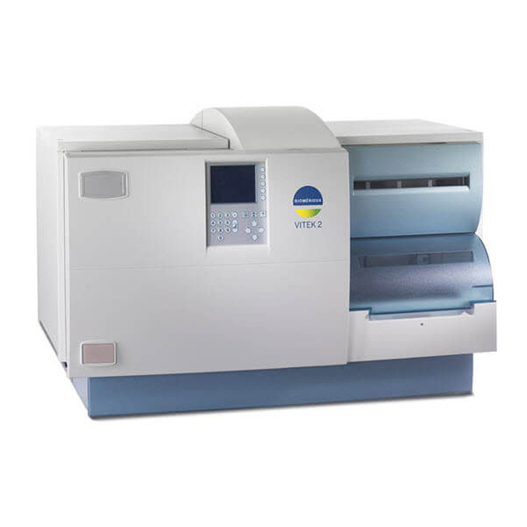
bioMerieux VITEK 2 User manual

bioMerieux
bioMerieux NucliSENS easyMAG User manual

bioMerieux
bioMerieux VITEK 2 User manual
