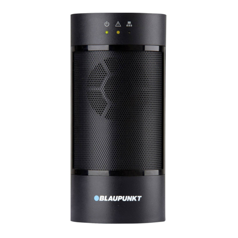
Blaupunkt Q-Pro6300 User manual

Smart Home Alarm System
Enjoy it.
Quick Start Guide
Q-Pro Alarm System & Smart Home


PL Instrukcja szybkiego startu
Q-Pro & Zestaw startowy
59
FI Pikaopas
Q-Pro & Aloituspaketti
70
Enjoy it.
EN Quick Start Guide
Q-Pro & Starter Kit
4
DE Schnellstart-Anleitung
Q-Pro & Starter-Kit
15
FR Guide de démarrage rapide
Q-Pro & Kit de démarrage
26
IT Guida di avvio rapido
Q-Pro & Kit iniziale
37
ES Guía rápida
Q-Pro & Kit de Inicio
48

4
English
English | Quick Start Guide
a
Q-ProHub – Central Panel
1. Content Q-Pro6300, Q-Pro6600 & Q-Pro System Panel
c
b
AC Adaptor Ethernet Cable
e
Stand base
g
f
Premium voucher Alarm-Sticker
Incl. in Q-Pro6300 Incl. in Q-Pro6600
i
Pet Immune
Motion Detector
l
j
Door Contact Pet immune
PIR Camera
Door Contact
m
NOTE:
This Quick Start Guide focuses on the installation and 1st time conguration of the
Security System with the Secure4Home APP. For more information,
please visit our website: service.blaupunkt-security.com
d
Mounting bracket
h
Quick Start Guide
k
Remote
Control
Remote
Keypad
n
PREMIUM
VOUCHER

5
English
IMPORTANT - Read before installation
• Make sure the installation sight is close to the router or a network Ethernet port.
• Do not install the Q-ProHub at open visible sight to avoid non-authorized manipulation.
• Tamper protection for the Q-ProHub is working only for wall installation. This is because the detachment of the
Q-Pro from the wall mounting bracket will activate the tamper alarm.
• The Q-ProHub tamper is pressed by the wall mounting bracket. Do not remove the wall mounting bracket even if you
decide to use the desk-stand. The Q-ProHub will not function properly without the mounting bracket attached at its back.
1. Status LED (Red & Green)
Red On – Arm mode
Red Flash – Home mode
Green Flash – Learning mode
Green Off – Walk Test mode or Disarmed
2. Alarm & Fault Status LED (Red & Yellow)
Red On – Alarm in Memory
Red Flash – Alarm
Yellow On / Flash – System Fault
3. Standing Bracket (For desktop deployment)
4. USB Port: For DG2-Pro and DG4-Pro
5. Learn / Reset Button
6. Ethernet Port
7. ON/OFF Battery Power Switch
8. Power Supply connector. DC 12V 1A
9. Panel Tamper
10. Wall Mounting Knockouts x 2
11. Bracket Hooks
12. Mounting Bracket
2. Q-ProHub Appearance
1
2
3
4
5
6
7
8
9
10 10
12
11 11
1
2
3
4
5
6
7
8
9
12
11
10

6
English
Option B: Desk Stand installation
Remove the strip located on the left side of the Q-ProHub.
Hook the Q-ProHub to the stand base pointing to the left
and slide it to the right.
Despite of the desk stand installation, please hook the
Q-ProHub to the mounting bracket and slide it to the left
to press the tamper protection inside the Q-ProHub, to
assure that the tamper is pressed.
Step 3b:
Step 2b:
Step 1b:
Option A: Wall installation
Place the wall mounting bracket on the wall in vertical
position and use it as a template to mark the positions of
the two holes on the wall.
Drill two holes on the marked positions into the wall
and place the wall mounting bracket with the hooks
pointing to the right. Fix the wall mounting bracket with
the screws and dowel provided.
Hook the Q-ProHub to the mounting bracket and slide
it to the left to press the tamper protection inside the
Q-ProHub. Optional: mark on wall or panel bottom how
to unhook the panel from the bracket.
Step 3a:
Step 2a:
Step 1a:
Step 4:
Connect the Q-ProHub to
the internet router with
the included ethernet
cable.
Step 5:
Connect Q-ProHub to an
electricity socket with the
included AC Adaptor. Flip
the Battery Power Switch
to ON with a thin screw
driver or pen.
Step 6:
Wait until the Power LED
lights up.
NOTE: As soon as the Q-ProHub is connected and switched on, the server gives you 15 minutes in order to
complete the registration. If the registration is not completed within 15 minutes, please remove the AC Adaptor
and move the switch to the OFF position.Then restart by reinserting the AC Adaptor and switching to ON. You
now have 15 more minutes to complete the registration.
Note:
The Q-ProHub has to be connected to Ethernet and
electricity at all times. Any problem with the router and
the connection to the network and power may disturb the
operation of the system.
3. Q-ProHub Installation

7
English
4. Registration
For computer registration visit https://eu. bphomeconnect.com from your Web Browser and follow the same
steps as bellow. Avoid using Web Browsers as Microsoft IE Explorer/ Edge.
5. Default Security Codes change
Step 1:
Please download and install the“Secure4Home” APP to your smartphone.
Step 2:
Launch the Secure4Home app and select First Time Registration
Step 3:
Ensure that the Q-ProHub is powered ON and connected to the router.
Step 4:
Follow the instructions on screen and enter the required information. Username and
password need to have at least 8 characters.
Secure4Home
You will be asked to enter the MAC address of your Security System, which you will find on the back of the Q-ProHub. Please
enter the last 6 digits of the MAC address. Input a name for you security system and select the appropriate language and
country.
Step 5:
Once the registration choose your service plan. With the Premium Service Voucher code you can try out the Premium Service
for free for one month. For more information on the premium service, please refer to chapter 12“Premium Service”.
Step 6:
You will receive an account authentication e-mail. Go to your e-mail inbox and authenticate your account.
Launch the Secure4Home app and enter your username and password.
At the top right corner tap on the engine icon. Tap on “Code”and type your user account password.
User PIN:
Here you can edit and create new“User PIN Codes”. Rename the default “user”
and change the default user PIN (1234) with a 4 digit code from your own.
Select Latch and save the settings. User PIN code is used to Arm, Home Arm
and Disarm the Security System.
Master Code:
Replace the default master code (1111) with a 4 digit code from your own and
save the settings. Master Code is used for configuration to access to the Security
System settings.
NOTE: User PIN Code and Master PIN Code cannot be identical. If they are identical, the System Mode change
will not work. For more information, see the Home Connect Server Manual. For conguration of the Arm Home
Mode, see chapter 2.6.1 Device Setting in the Home Connect Server Manual (Download at service.blaupunkt-se-
curity.com).
The Secure4Home App is intended to register and manage your Security System from anywhere.
For conguration please refer to chapter 10“Operation through the Web Portal”.

8
English
6. Kit Accessories Installation
Door Contact (DC-S4)
(included in Kit Q-Pro 6300/6600)
The Door Contact DC-S4 monitors doors and windows in your home
ensuring ideal protection.
The DC-S4 can be mounted with screws or with adhesive tape to the door
or window frame. For a proper operation we do not recommend to install
the DC-S4 on steel doors/windows.
For screw installation, remove the back cover and push through the 2
knockouts on the back (for example with a screwdriver) where plastic is
thinner. Drill holes into the surface using the knockouts as template. Fix the
Door Contact base onto the surface with the screws and plugs provided.
Place the back cover again onto the Door Contact.
Make sure that the tamper protection is pressed down against the door/
window surface, otherwise the accessory will trigger a tamper alert.
The magnet should be installed adjacently at the sensor mark. Fix the
magnet in the same way as the main body of the door contact, either by
screw installation or adhesive tape. The Magnet has to be placed next to the
Sensor marker! Max 15mm
Fig.1
LED / Test-/
Learn Button
Tamper protection
Sensor
marker
Magnet
Remote-Control (RC-R3B)
(included in Kit Q-Pro 6300)
With the Blaupunkt Remote Control RC-R3B you can easily change the
status of the system between Arm, Disarm and Home mode.
Additionally the RC-R3B can be used to trigger a panic alarm by pressing
the emergency button for 3s. The RC-R3B cannot disarm a panic alarm
triggered by itself, it can be done via the App.
The RC-R3B works with rolling code encryption technology, for an
improved security against manipulation by third parties.
Fig.2
LED
Arm Away-Button Arm Home-Button
Emergency-
Button
Disarm-Button Battery Cover
Pet immune Motion Detector (IR-P4)
(included in Kit Q-Pro 6300)
When the IR-P4 detects a movement during arm mode, it will
automatically trigger an alarm and notify the user. The tamper protection
is inside the device and is pushed down by the screw. If the device is
removed by an intruder, the tamper protection will trigger an alarm.
The IR-P4 needs to be mounted or glued to the wall with screws or
adhesive tape. The best location is in a corner to have wide motion
detection range. Install the motion detector at 2m above the ground for
best performance.
Remove the back cover and push through the knockouts on the back
(for example with a screwdriver) where plastic is thinner. There are six
knockouts on the back of the device that can be pushed though. If you
mount the device in a corner, push through the perforations on the side; if
you mount the device on a plane surface, push through the perforations in
the center. Drill holes into the wall using the knockouts as template. Fix the
IR-P4 base onto the wall with the screw and plugs provided. Place back the
back cover onto the IR-P4.
The pet immune feature will ignore pets up to 25 kgs. For a correct pet
immune detection do not aim the motion detector at stairways or areas
where a pet can climb on.
LED/Walk Test/
Learn Button
PIR-Sensor
Fig.3
NOTE: The IR-P4 will go on sleep mode
for 1 min. when detecting someone
while alarm is deactivated. Please wait
more than 1 minute without detecting
anyone to be sure the device its out of
sleep mode before testing.
9
English
Remote Keypad (KP-R1)
(included in Kit Q-Pro 6600)
With the Blaupunkt keypad KP-R1 You can easily change the status
of the Security System between Arm, Disarm and Home mode.
Enter the Security System PIN code (same as set in chapter 5) and
press the desired mode button.
We recommend to mount the keypad at the door entrance for
entry control.
Remove the back cover and push through the 2 knockouts on the
back (for example with a screwdriver) where plastic is thinner. Drill
holes into the wall using the knockouts as template. Fix the keypad
base onto the wall with the screw and plugs provided. Place back
the back cover onto the Keypad.
Make sure that the tamper protection is pressed down against the
wall surface, otherwise the accesory will trigger a tamper alert.
1
2
3
4
5
6
7
1. Active LED (Blue/Orange)
2. Status LED (Blue/Red)
3. Fault LED (Orange)
4. Away Arm Key
5. Home Arm Switch
6. Status Key
7. Disarm Key
Pet immune Motion Detector with camera (IRC-P4)
(included in Kit Q-Pro6600)
When the IRC-P4 detects an movement during arm-mode, it will
automatically take 3 photos, save them on the cloud, trigger an
alarm and notify the user. User can request and see the photos at
any time using the App or the Web Portal. The tamper protection
is inside the device and is pushed down by the screw. If the device
is removed by an intruder, the tamper protection will trigger an
alarm.
The IRC-P4 needs to be mounted or glued to the wall with screws
or adhesive tape. The best location is in a corner to have wide
motion detection range. Install he motion detector at 2m above
the ground, for best performance.
Remove the back cover and push through the knockouts on the
back (for example with a screwdriver) where plastic is thinner.
There are six knockouts on the back of the device that can be
pushed through If you mount the device in a corner, push through
the perforations on the side; if you mount the device on a plane
surface, push through the perforations in the center. Drill holes
into the wall using the knockouts as template. Fix the IRC-P4 base
onto the wall with the screw and plugs provided. Place back the
back cover onto the IRC-P4.
The pet immune feature and will ignore pets up to 25kg. For a
correct pet immune detection do not aim the motion detector at
stairways or areas where a pet can climb on.
Fig.4
NOTE: The IRC-P4 will go on sleep mode for 2
min. when detecting someone while alarm is
deactivated. Please wait more than 2 minutes
without detecting anyone to be sure the
device is out of sleep mode before testing.
For more information about the accessories included on the kit visit service.blaupunkt-security.com for detailed
user manual for each accessory.
The Q-Pro Series equipped with rolling code. A feature to encrypt and make the Security System even more
secure against so called replay attacks.
LED-Flash
PIR-Sensor
Lense of PIR-
Camera
Blue LED/Test-/
Learn-Button Fig.5

10
English
7. Operation through App
The Secure4Home App is intended to register and manage your Security System from anywhere. For
conguration please refer to chapter 10“Operation through the Web Portal”.
On the Cam Menu you can see the
Optional Video Survaillance WiFi Camera
(IPC-S1) and the optional PIR photo
camera (IRC-P4 or IRC-S2).
The IPC-S1 provides you a reliable
HD-quality video surveillance with
automatic video recording during
alarms, live-streaming, two-way voice
communication and night vision.
The IRC-P4 triggers an alarm when
movement is detected and captures
3 colour photos to provide visual
verification/ evidence.
In the Automation
Menu you can trigger
manually any of your
scenarios, control
group accessories,
manage and use
individually all the
Home Automation
accessories and
activate or deactivate
existing rules.
In the Events Menu,
you will get an
overview of past
events. You can mail/
forward events or call
someone in order to
notify of the alarm.
All the intrusion alarms
will be displayed in
red, while technical
alerts or system
changes will be
displayed in yellow.
If you click on the settings icon at the
top right, you can access your personal
info, modify your password, configure
notification, setup an App startup page,
bypass any accesory and find contact
support information. You can also log
out.
In the Security Menu
you can change the
System Modes, check
the System Dashboard
status, if there is any
Door Contact open
and if your accessories
have any fault.
If a GSM module is
installed on the panel
the signal strenght
will (see chapter 12)
be displayed at the
top right.
In the Device Menu you can have a
general overview of all the accesories,
check if there is any fault on them and if
the Door contacts are open or closed.
If one or more accessories show low
battery you should replace it so the
sytem continues working properly.
If any other supervision failiures
are displayed please follow the
troubleshooting in the manual of the
specific accessory device in the full
manual to solve the issue.

11
English
9. Learn in new additional Accessories
All new accessories which where not included in the Kit Content must be added to the Q-ProHub with the following steps.
You can add up to 50 accessories.
To learn in any new accesory you should go to the Home Portal “eu.bphomeconnect.com“.
Step 1:
Go to Settings and click on Device.
Step 2:
Click on the icon at the top right corner
to access the“Add Device”function.
Step 3:
Refer to each accessory device manual to
transmit the “learn signal”from each device.
When the Q-ProHub receives the“learn signal”,
it will emit a double beep tone and the web
interface will display the device info.
Step 4:
Check the box in front of device info, then click
OK to add the device into the Q-ProHub.
8. System Modes
Disarm: The Disarm Mode disarms
all burglary sensors.
Arm Away: The Arm Away Mode
arms all burglary sensors. An alarm
is triggered as soon as a sensor
is activated. If a sensor has been
assigned the attribute Entry, an
Entry- Countdown is triggered,
so the user has time to disarm
the system and no alarm will be
triggered.
Arm Home:
Sensors that have been assigned
the Arm Home attribute, cannot be
activated if the system is switched
into the Arm Home Mode. Usually
motion detectors in the interior
are assigned this attribute, so that
you can move freely inside the
appartment while the doors and
windows are protected.
Step 1:
Click the System Mode
Button that you would like
to activate.
Step 2:
Enter the PIN Code
(default code: 1234). If the
code is correct the Mode
change will be applied
and new selected mode
will light up.
Step 5:
Give the new accessory a name and edit attributes, by clicking on the 3 dots on the right side of this accessory.

12
English
10. Operation and configuration through the Web Portal
In the Security Menu, you are able
to change the System modes and
to get an overview of the devices
and manually request a photo
image.
For Automation Menu, please
refer to 11. Home Automation.
In the Camera Menu you will see
your real-time video as soon as
you have integrated the IPC-S1
Blaupunkt Camera.
In the Events Menu, you will get
an overview of the events reported
to the Q-ProHub.
In the Settings Menu you can
program the Q-ProHub settings.
NOTE: Only ONE user at a time can be
logged into the account with an
identical user name.
To change Account Settings, click on your account name (top right corner)
and select “Account”.
On this menu you can change your account details, Home Portal language
and create secondary user accounts. To edit, click, once finished click
submit on the bottom to save the changes.
Secondary user accounts are tied to a main account. User and password for
secondary accounts are only for login on Home Portal and app. PIN for arm/
disarm are tied to the Q-ProHub and will remain the same.
Go to the Home Portal “eu.bphomeconnect.com“.
Overview Web Portal:
NOTE: Make sure that the volume in
your smartphone settings has been
set to high for Push and call Reports.
To change the Notification settings click on
your account name (top right corner) and select
“Notification”.
In the Notication Menu you are able to modify
the notification settings:
Push: Setup the push configurations for your
smartphone. Secure4Home app needs to be
installed and logged to receive push notifications.
E-mail: The Home Portal server will send an e-mail
to the configured e-mail account.
Voice Message: Blaupunkt Alarm center will
automatically call you on the case of a burglar
event. Only for premium users, for more information
regarding premium service please refer to chapter
12, Premium Service.
Conguration via Web Portal:

13
English
11. Home Automation
To make any changes to your Home Automation you need to go to the Home Portal
“eu.bphomeconnect.com“.
Device - Allows you to manage and use
individually all the Home Automation accessories.
Room - Assign each accessories to the appropriate
room for easier management. (only for Home
Automation accessories)
Group - You can add accesories of the same type
to a group to manage all the accesories with a
single command.
Scenario - Create your scenario to define preset
actions for your Home Automation accessories.
Scenarios can be triggered via the scenario swich
selector (SSW-S1) or your mobile. The maximum
amount of actions per Scenario is 5.
Rule - Create your rule to initiate automatic actions
of your panel and Home Automation devices
under a trigger & conditions.
How to create a rule:
Step 1: Go to Automation - Rule and click the + button.
Step 2: Write a name for the rule, e.g.“Auto Arm”.
Step 3: Select a trigger for the rule. (e.g. “Schedule”--> “Every Week“
select the days and time)
Step 4: If you want, add any condition (status of system for the rule
to happen). E.g time period or system mode, up to 2 conditions.
Step 5: Select from the list an action to trigger rule. E.g. Device
action --> Power swich ( PSM-S1) to Switch On.
Step 6: If you would like to add more actions press the +
button on the right (up to 5 actions are possible).
Step 7: Click“Submit”to save the changes.
Recomended Rules Trigger Condition Action
Whenever there is an alarmTurn the
lights ON, roll the blinds UP and start a
video recording.
Trigger alarm
Alarm --> Any
alarm
None "Device Action --> Power Switch PSM-S1 or PRM2-S1 --> ON
Device Action --> Roller Shutter SCM-S1 Open 100%
Request Video --> IPC-S1"
When you open the door of your
home between 19:00 and 7:00 turn
the lights ON for 20s
Door Contact
Open
Time Period -->
Daily --> From
19:00 to 7:00
Device Action --> Power Switch PSM-S1 or PRM2-S1 --> ON for -> 20 seconds
Simulate presence when you are on
holidays:
Eveyday at specific times e.g. 20:00 the
blinds will turn UP and the light will turn
ON by 30minutes."
Schedule -->
Weekly ->
Everyday 20:00
None "Device Action --> Power Switch PSM-S1 or PRM-S1 --> ON for -> 30min
Device Action --> Roller Shutter SCM-S1 Close"
Everyday at 6:00 change the Security
system to disarm and open your blinds Schedule -->
Weekly ->
Everyday 6:00
None "Mode Change --> Disarm
Device Action --> Roller Shutter SCM-S1 Open 100%"
Whenever you Arm the system turn
OFF your lights, turn down the heating
system to 18ºC and close your blinds
Mode Change
--> Arm
None "Device Action --> Power Switch PSM-S1 or PRM-S1 --> OFF
Device Action --> ThermostatTRV-S1 or TMST-S1 --> ON ->18ºC
Device Action --> Roller Shutter SCM-S1 Close"
Everyday at 23:00 change the Security
system to Home arm, turn all the lights
OFF, close all your blinds and turn
down the heating system to 18ºC.
Schedule -->
Weekly ->
Everyday 23:00
None "Mode Change --> Home Arm
Device Action --> Power Switch PSM-S1 or PRM-S1 --> OFF
Device Action --> Roller Shutter SCM-S1 Close
Device Action --> ThermostatTRV-S1 or TMST-S1 --> Turn Down to 18ºC"

14
English
12. Security Recommendations
1| Hybrid Backup communication method:
You can acquire and connect the Blaupunkt DG2-Pro or DG4-Pro GSM modules to the USB located at the back of the
Q-ProHub to avoid losing communication with your security system even if the Internet connection fails or it’s cut off by an
intruder.
The DG2-Pro works on 2G network and offers backup for alarm notifications and standard App overview we recommend to
use this backup option in areas where there is no 4G communication.
The DG4-Pro works on 4G high speed network and can be used as backup for alarm notifications and standard App
management. Please assure that there is 4G network on the instllation location. We do not recommend to use the DG4-Pro
as standalone communication method, it is meant to be backup only.
The GSM modules would need to have a SIM card installed with available Internet data. (SIM card not included)
2| Mute the Q-ProHub siren:
To avoid that an intruder locates where the Q-ProHub is installed we recommend to mute the internal siren from the
Q-ProHub and install an outdoor or indoor additional siren.
You can install one of the following additional sirens to increase security and prevent the panel to be found by a intruder:
Indoor AC powered siren: SRAC-S1, Indoor battery siren SR-S1 or Outdoor battery siren BX-S1).
To mute the internal siren please go to Settings --> Type the Master Code --> Panel --> Internal Siren --> OFF.
3| Premium service:
With the Blaupunkt Premium Service, your Security System will be enabled with a innovative feature set:
Our premium call notifications will provide automatic calls to up to 3 different Telephone numbers by our alarm center in
case of an intrusion. This works additional to the standard Push-message and E-Mail service.
Premium Service additionally offers a cloud storage of more than 50 field event Videos of your IPC-S1, 30 captured images of
the PIR-Photo-Camera (IRC-P4 and IRC-S2) and a general EventLog of 90 days.
Additionally with the 12 months Premium Service Plan product warranty will be extended one aditional year.
For more information on the Premium Service, go to: premium.blaupunkt-security.com
13. Support
For more information on Q-ProHub and accesories, please visit
security.blaupunkt-service.com
Blaupunkt Competence Center Security & Care
www.blaupunkt.com
Security Brand Pro GmbH
Mondstrasse 2-4
85622 Feldkirchen-München, Germany
© Technical changes and errors excepted
4| Firmware Updates:
The Q-ProHub includes an automatic FW upgrade service. (There is a daily FW upgrade service which keeps your device up-to
date.). If you bought a new Q-Series product you should wait at least one working day so all the necessary updates are ready.
If the device is updating please don’t turn it off since it could harm the Security System.

15
Deutsch
Deutsch | Schnellstart-Anleitung
a
Q-ProHub – Alarmzentrale
1. Inhalt Q-Pro6300, Q-Pro6600 & Q-Pro Alarmzentrale
c
b
Netzteil Ethernetkabel
e
Standfuß
g
f
Premium-Service Gutschein Alarm-Aufkleber
Inkl. im Q-Pro6300 KIT Inkl. im Q-Pro6600 KIT
i
Tierimmuner
Bewegungsmelder
l
j
Tür/
Fensterkontakt
Tierimmuner
Bewegungsmelder
inkl. PIR-Kamera
Tür/
Fensterkontakt
m
HINWEIS:
Diese Kurzanleitung konzentriert sich auf die Installation und die erstmalige Konguration des
Sicherheitssystem mit der Secure4Home-APP. Für mehr Informationen besuchen Sie bitte unsere
Website: service.blaupunkt-security.com
d
Montagehalterung
h
Schnellstartanleitung
k
Funk-
Fernbedienung
Funk-
Bedienteil
n
PREMIUM
SERVICE
GUTSCHEIN

16
Deutsch
WICHTIG - Vor der Installation lesen
• Stellen Sie sicher, dass sich die gewünschte Installationsposition in der Nähe des Routers oder eines
Netzwerk-Ports befindet.
• Installieren Sie den Q-ProHub nicht an einem offen sichtbaren Ort, um Manipulationen zu vermeiden.
• Der Sabotageschutz für das Q-ProHub funktioniert nur für die Wandmontage. Dies liegt daran, dass durch das
Abnehmen des Q-ProHub von der Wandhalterung der Sabotagealarm ausgelöst wird.
• Der Q-ProHub Sabotagekontakt wird durch das Einrasten der Wandhalterung deaktiviert. Entfernen Sie die
Wandhalterung nicht, auch wenn sie den Standfuß nutzen. Der Q-ProHub funktioniert nicht ordnungsgemäß, wenn die
Wandhalterung nicht angebracht ist.
1. Status-LED (Rot/Grün)
Rot AN – Scharf-Modus
Rot blinkt – Zuhause-Modus
Grün blinkt – Lernmodus
Grün aus – Signalreichweitentest oder Unscharf-Modus
2. Alarm- und Fehlerstatus-LED (Rot/Gelb)
Rot AN – Alarm gespeichert
Rot blinkt – Alarmmeldung
Gelb AN / blinkt – Fehler im System
3. Standfuß
4. USB-Anschluss: Für DG2-Pro und DG4-Pro
5. Lern- / Reset-Taste
6. Ethernet Anschluss
7. EIN / AUS-Batterie-Netzschalter
8. Netzteilanschluss. DC 12V 1A
9. Sabotagekontakt
10. Montagelöcher für Wandmontage x 2
11. Halterungshaken
12. Wandhalterung
2. Q-ProHub Gerätebeschreibung
1
2
3
4
5
6
7
8
9
10 10
12
11 11
1
2
3
4
5
6
7
8
9
12
11
10

17
Deutsch
Option B: Standfuß installation
Entfernen Sie den schwarzen Klebestreifen auf der linken
Seite des Q-ProHub.
Setzen Sie das Q-ProHub auf den Standfuß. Die Haken
des Standfußes müssen wie abgebildet nach links zeigen.
Schieben Sie daraufhin den Standfuß nach rechts bis dieser
einrastet.
Der Q-ProHub Sabotagekontakt wird durch das einrasten
der Wandhalterung deaktiviert. Daher müssen Sie auch,
wenn Sie den Standfuß nutzen die Wandhalterung mit dem
Q-ProHub verbinden. Legen Sie hierfür die Wandhalterung
auf das Q-ProHub und schieben die Wandhalterung nach
rechts bis diese in das Q-ProHub einrastet.
Schritt 3b:
Schritt 2b:
Schritt 1b:
Option A: Wandinstallation
Bringen Sie die Wandhalterung in vertikaler Position an
der Wand an und verwenden Sie diese als Vorlage, um die
Positionen der beiden Löcher an der Wand zu markieren.
Bohren Sie zwei Löcher an den markierten Stellen in die
Wand und platzieren Sie die Wandhalterung mit den Haken
nach rechts. Befestigen Sie die Wandhalterung mit den
mitgelieferten Schrauben und Dübeln.
Hängen Sie den Q-ProHub in die Wandhalterung und
schieben Sie diese nach links, um den Sabotagekontakt in
dem Q-ProHub einzudrücken. Optional: Markieren Sie an
der Unterseite der Wand oder der Alarmzentrale, wie Sie die
Alarmzentrale von der Wandhalterung lösen können.
Schritt 3a:
Schritt 2a:
Schritt 1a:
Schritt 4:
Verbinden Sie das
Q-ProHub über das
mitgelieferte Ethernetkabel
mit dem Router.
Schritt 5:
Schließen Sie das Q-ProHub mit
dem mitgelieferten Netzteil an
eine Steckdose an. Schieben Sie
den Batterie-Netzschalter mit
einem Schraubendreher oder
Stift auf ON.
Schritt 6:
Warten Sie, bis die
Power-LED leuchtet.
HINWEIS: Sobald das Q-ProHub angeschlossen und eingeschaltet ist, gibt Ihnen der Server 15 Minuten Zeit, um
die Registrierung abzuschließen. Wenn die Registrierung nicht innerhalb von 15 Minuten abgeschlossen ist,
entfernen Sie bitte das Netzteil und bringen Sie den Batterie-Netzschalter in die Position OFF. Starten Sie dann
das Q-ProHub neu, indem Sie das Netzteil wieder einstecken und den Batterie-Netzschalter in die Position ON
schalten. Sie haben jetzt weitere 15 Minuten Zeit, um die Registrierung abzuschließen.
Hinweis:
Das Q-ProHub muss immer mit dem Netzwerkkabel und
Netzteil verbunden sein. Probleme mit dem Router und
der Verbindung zum Netzwerk und zur Stromversorgung
können den Betrieb des Systems stören.
3. Q-ProHub Installation

18
Deutsch
4. Anmeldung
Für die Computerregistrierung besuchen Sie https://eu.bphomeconnect.com von Ihrem Webbrowser aus und
befolgen Sie die gleichen Schritte, wie unten beschrieben. Vermeiden Sie die Verwendung von Webbrowsern,
wie Microsoft IE Explorer / Edge. Wir empfehlen die Browser Mozilla Firefox und Google Chrome.
5. Standard-Sicherheitscodes ändern
Schritt 1:
Laden Sie die “Secure4Home”APP auf Ihr Smartphone herunter und
installieren Sie diese.
Schritt 2:
Starten Sie die Secure4Home-App und wählen Sie“Erstmalige Registrierung”.
Schritt 3:
Stellen Sie sicher, dass das Q-ProHub eingeschaltet und mit dem Router verbunden ist.
Schritt 4:
Folgen Sie den Anweisungen auf dem Bildschirm und geben Sie die erforderlichen
Informationen ein. Benutzername und Passwort müssen mindestens 8 Zeichen umfassen.
Secure4Home
Sie werden aufgefordert, die MAC-Adresse Ihres Sicherheitssystems einzugeben, die Sie auf der Rückseite des Q-ProHub
finden. Bitte geben Sie die letzten 6 Ziffern der MAC-Adresse ein. Geben Sie einen Namen für Ihr Sicherheitssystem ein und
wählen Sie die entsprechende Sprache und das Land aus.
Schritt 5:
Nach der Registrierung wählen Sie Ihren Serviceplan aus. Mit dem Code des Premium Service Voucher können Sie den
Premium Service einen Monat lang kostenlos testen. Weitere Informationen zum Premium-Service Gutscheins finden Sie in
Kapitel 12„Premium-Service“.
Schritt 6:
Sie erhalten eine E-Mail mit der Kontoauthentifizierung. Gehen Sie zu Ihrem E-Mail-Posteingang und authentifizieren Sie Ihr
Konto.
Starten Sie die Secure4Home-App und geben Sie Ihren Benutzernamen und Ihr Passwort ein.
Tippen Sie oben rechts auf das Einstellungssymbol. Tippen Sie auf “Code”und geben Sie Ihr Benutzerkontokennwort ein.
Benutzer-PIN:
Hier können Sie neue„Benutzer-PIN-Codes“ bearbeiten und erstellen. Benennen
Sie den Standardbenutzer um und ändern Sie die Standardbenutzer-PIN
(1234) mit einem vierstelligen Code. Wählen Sie“Verriegeln”und speichern
Sie die Einstellungen. Der Benutzer-PIN-Code wird verwendet, um das
Sicherheitssystem in den Scharf, Zuhause-, Unscharf-Modus zu versetzen.
Master-PIN-Code:
Ersetzen Sie den voreingestellten Master-PIN-Code (1111) durch einen
vierstelligen Code, und speichern Sie die Einstellungen. Der Mastercode wird
für die Konfiguration verwendet, um auf die Sicherheitssystemeinstellungen
zuzugreifen.
HINWEIS: Der Benutzer-PIN-Code und der Master-PIN-Code können nicht identisch sein. Wenn diese identisch
sind, funktioniert die Änderung des Systemmodus nicht. Weitere Informationen nden Sie im Home Connect
Server-Handbuch. Zur Konguration des Zuhause-Scharf-Modus siehe Kapitel 2.6.1“Geräteeinstellung”im
Home Connect Server-Handbuch (Download unter service.blaupunkt-security.com).
Mit der Secure4Home App können Sie Ihr Sicherheitssystem bequem registrieren und von überall aus
verwalten. Informationen zur Konguration nden Sie in Kapitel 10„Bedienung über das Webportal“.

19
Deutsch
6. Installation des Kit-Zubehörs
Tür/Fensterkontakt (DC-S4)
(im Kit Q-Pro6300/6600 enthalten)
Der Tür/Fensterkontakt DC-S4 überwacht Türen und Fenster in Ihrem
Zuhause und gewährleistet einen idealen Schutz.
Der DC-S4 kann mit Schrauben oder Klebeband am Tür- oder
Fensterrahmen montiert werden. Für einen ordnungsgemäßen Betrieb
empfehlen wir, den DC-S4 nicht an Stahltüren oder Stahlfenstern zu
installieren.
Entfernen Sie für die Schraubenmontage die hintere Abdeckung
und drücken Sie (z. B. mit einem Schraubendreher) durch die zwei
Aussparungen auf der Rückseite an der Stelle, an der der Kunststoff dünner
ist. Bohren Sie Löcher in die Oberfläche, wobei Sie die Aussparungen
als Schablone verwenden. Befestigen Sie die Türkontaktplatte mit den
mitgelieferten Schrauben und Dübeln an der gewünschten stelle. Setzen
Sie die hintere Abdeckung wieder auf den Türkontakt.
Stellen Sie sicher, dass der Sabotagestift gegen die Tür- / Fensteroberfläche
gedrückt wird. Andernfalls löst das Zubehör einen Sabotagealarm aus.
Der Magnet sollte neben der Sensormarkierung installiert werden.
Befestigen Sie den Magneten genauso wie das Hauptteil des Türkontakts,
entweder mit den Schrauben oder dem Klebeband.
Der Magnet muss neben der
Sensormarkierung platziert werden!
Max 15 mm
Abb.1
LED / Test- /
Lerntaste
Sabotagekontakt
Sensor-
markierung
Magnet
Fernbedienung (RC-R3B)
(im Kit Q-Pro6300 enthalten)
Mit der Blaupunkt-Fernbedienung RC-R3B können Sie den Status des
Systems zwischen Scharf, Unscharf und Zuhause-Modus leicht ändern.
Zusätzlich kann mit dem RC-R3B ein Panikalarm ausgelöst werden, indem
die Notfall-Taste für 3 Sekunden gedrückt halten. Der RC-R3B kann einen
von ihm ausgelösten Panikalarm nicht deaktivieren. Dies kann nur über die
App oder den Browser erfolgen.
Der RC-R3B arbeitet mit der Rolling-Code Verschlüsselungstechnologie,
um die Sicherheit gegen Manipulationen durch Dritte zu erhöhen.
Abb.2
LED
Scharf-Taste Zuhause-Taste
Notfall-
Taste
Unscharf-Taste Batterieabdeckung
Tierimmuner Funk-Bewegungsmelder (IR-P4)
(im Kit Q-Pro6300 enthalten)
Wenn der IR-P4 im Scharf-Modus eine Bewegung erkennt, wird
automatisch ein Alarm ausgelöst und der Benutzer benachrichtigt. Der
Sabotageschutz befindet sich im Gerät und wird durch die Schraube nach
unten gedrückt. Wenn das Gerät von einem Eindringling entfernt wird, löst
der Sabotagealarm umgehend aus.
Der IR-P4 muss mit Schrauben oder Klebeband an der Wand befestigt
oder geklebt werden. Der beste Ort ist in einer Ecke mit einem
möglichst großen Bewegungserkennungsbereich. Installieren Sie den
Bewegungsmelder 2 m über dem Boden, um eine optimale Sicherung zu
erzielen.
Entfernen Sie die hintere Abdeckung und drücken Sie (z. B. mit einem
Schraubendreher) durch die Aussparungen auf der Rückseite, an der
Stelle, an der der Kunststoff dünner ist. Es gibt sechs Aussparungen auf
der Rückseite des Geräts. Wenn Sie das Gerät in einer Ecke montieren,
drücken Sie die seitlichen Aussparungen durch. Wenn Sie das Gerät auf
einer ebenen Fläche montieren, drücken Sie durch die Aussparungen in
der Mitte. Bohren Sie Löcher in die Wand, wobei Sie die Aussparungen als
Schablone verwenden. Befestigen Sie die hintere Abdeckung des IR-P4
mit den mitgelieferten Schrauben und Dübeln an der Wand. Setzen Sie die
rückseitige Abdeckung wieder auf den IR-P4.
Der IR-P4 ignoriert Haustiere bis zu 25 kg. Richten Sie den
Bewegungsmelder nicht auf Fensterfronten, Treppen oder auf Bereiche,
auf welche ein Haustier klettern kann.
LED/Test-/
Lerntaste
PIR-Sensor
Abb.3
HINWEIS: Der IR-P4 hat nach
Scharfschaltung eine 1-minütige
Energiesparmodus, in der er keine Bewe-
gungsereignisse erfasst. Bitte warten
Sie länger als 1 Minuten, bevor Sie das
Gerät testen.

20
Deutsch
Funk-Bedienteil (KP-R1)
(im Kit Q-Pro 6600 enthalten)
Mit dem Funk-Bedienteil KP-R1 können Sie den Status des
Sicherheitssystems leicht zwischen dem Scharf-, Unscharf- und
dem Zuhause-Modus ändern. Geben Sie den PIN-Code des
Sicherheitssystems ein (wie bereits in Kapitel 5 eingestellt) und
drücken Sie die gewünschte Modustaste.
Wir empfehlen, das Funk-Bedienteil hinter der Eingangstür für die
Zugangskontrolle zu montieren.
Nehmen Sie die hintere Abdeckung ab und drücken Sie (z. B. mit
einem Schraubendreher) durch die zwei Aussparungen auf der
Rückseite an der Stelle, an der der Kunststoff dünner ist. Bohren
Sie Löcher in die Wand, wobei Sie die Aussparungen als Schablone
verwenden. Befestigen Sie den Tastenfuß mit den mitgelieferten
Schrauben und Steckern an der Wand. Setzen Sie die rückseitige
Abdeckung wieder auf die Tastatur.
Stellen Sie sicher, dass der Sabotagestift gegen die Wandoberfläche
gedrückt wird. Andernfalls löst das Zubehör einen Sabotagealarm
aus.
1
2
3
4
5
6
7
1. Aktivitäts-LED (Blau/Orange)
2. Status-LED (Blau/Rot)
3. Fehler-LED (Orange)
4. Abwesend Scharf-Taste
5. Anwesend-Scharf Taste
6. Status-Taste
7. Unscharf-Taste
Tierimmuner Funk-Bewegungsmelder mit Kamera (IRC-P4)
(im Kit Q-Pro6600 enthalten)
Wenn der IRC-P4 im Scharf-Modus eine Bewegung erkennt,
nimmt er automatisch 3 Fotos auf, speichert sie in der Blaupunkt
Cloud, löst einen Alarm aus und benachrichtigt den Benutzer.
Der Benutzer kann die Fotos jederzeit über die App oder das
Webportal anfordern und anzeigen. Der Sabotageschutz befindet
sich im Gerät und wird durch die Schraube nach unten gedrückt.
Wenn das Gerät von einem Eindringling entfernt wird, löst der
Sabotageschutz einen Alarm aus.
Der IRC-P4 muss mit Schrauben oder Klebeband an der Wand
befestigt oder geklebt werden. Der beste Ort ist in einer Ecke
für einen großen Bewegungserkennungsbereich. Installieren Sie
den Bewegungsmelder in 2 m Höhe über dem Boden, um eine
optimale Sicherung zu erzielen.
Entfernen Sie die hintere Abdeckung und drücken Sie (z. B.
mit einem Schraubendreher) durch die Aussparungen auf der
Rückseite an der Stelle, an der der Kunststoff dünner ist. Es gibt
sechs Aussparungen auf der Rückseite des Geräts. Wenn Sie
das Gerät in einer Ecke montieren, drücken Sie die seitlichen
Aussparungen durch. Wenn Sie das Gerät auf einer ebenen Fläche
montieren, drücken Sie durch die Aussparungen in der Mitte.
Bohren Sie Löcher in die Wand, wobei Sie die Aussparungen als
Schablone verwenden. Befestigen Sie die hintere Abdeckung
des IRC-P4 mit den mitgelieferten Schrauben und Dübeln an der
Wand. Setzen Sie daraufhin die hintere Abdeckung wieder auf den
IRC-P4.
Der IRC-P4 ignoriert Haustiere bis zu 25 kg. Richten Sie den
Bewegungsmelder nicht auf Fensterfronten, Treppen oder auf
Bereiche, auf welche ein Haustier klettern kann.
Abb.4
HINWEIS: Der IRC-P4 hat nach Scharfschaltung
einen 2-minütigen Energiesparmodus, in der
er keine Bewegungsereignisse erfasst. Bitte
warten Sie länger als 2 Minuten, bevor Sie das
Gerät testen.
Weitere Informationen sowie eine detailierte Bedienungsanleitung zu den im Kit enthaltenen Zubehörteilen
nden Sie unter service.blaupunkt-security.com. Die Q-Pro6300/6600 ist mit Rolling Code ausgestattet. Eine
Funktion, die das Sicherheitssystem vor so genannten“Replay-Angrien”schützt.
LED-Blitz
PIR-Sensor
Linse der PIR-
Kamera
Blaue LED / Test-
/ Lerntaste Abb.5
This manual suits for next models
2
Table of contents
Languages:
Other Blaupunkt Security System manuals

Blaupunkt
Blaupunkt Q3000 User manual

Blaupunkt
Blaupunkt SRAC-S1 User manual

Blaupunkt
Blaupunkt SA 2700 User manual

Blaupunkt
Blaupunkt SA 2700 User manual

Blaupunkt
Blaupunkt SA 2700 User manual

Blaupunkt
Blaupunkt SA 2500 User manual

Blaupunkt
Blaupunkt PB-S1 User manual

Blaupunkt
Blaupunkt IRC-S2 User manual

Blaupunkt
Blaupunkt PB-S1 User manual

Blaupunkt
Blaupunkt Q SERIES Owner's manual