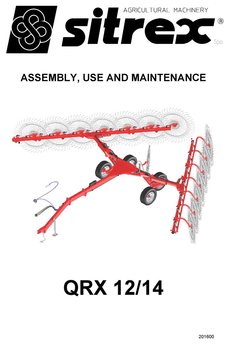
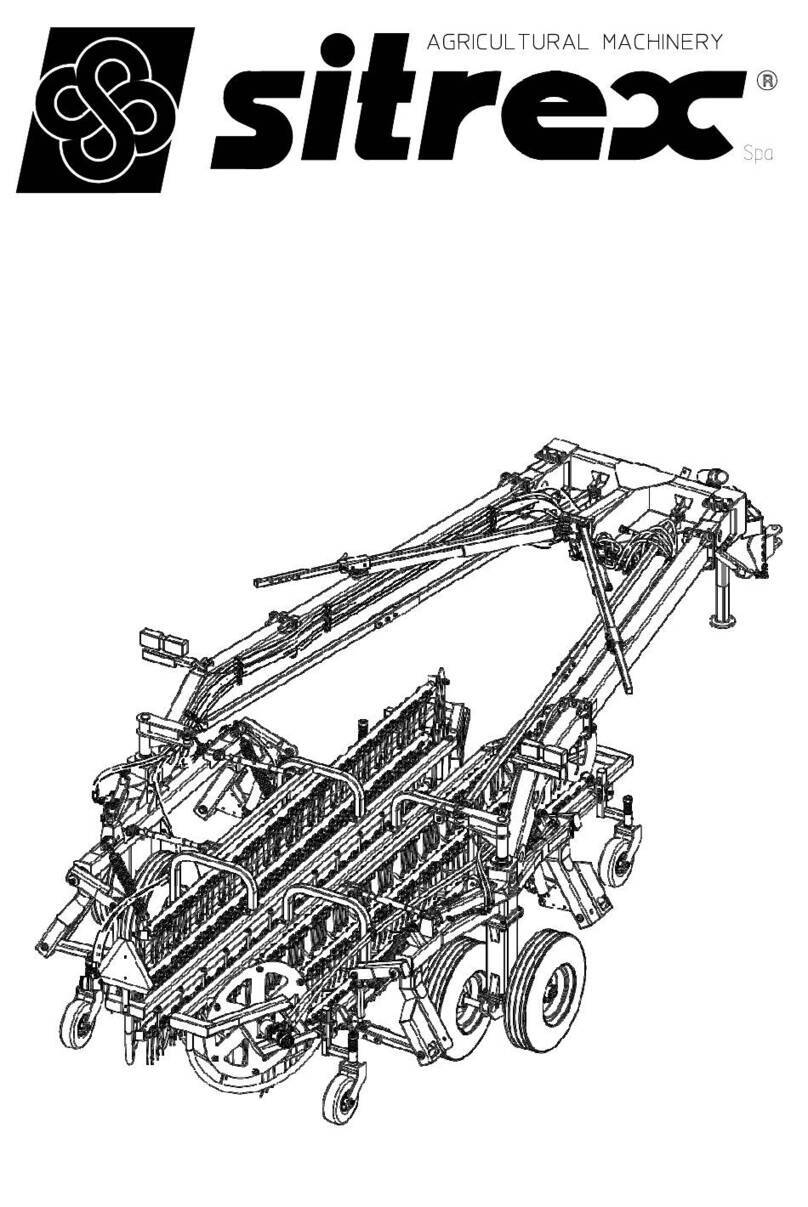
sitrex MX 8 Quick setup guide

ASSEMBLY, USE
AND MAINTENANCE
MX/8 - MX/10
05-18


1
CONTENTS
CONTENTS .................................................................................................................................. 1
1. Warrantee .............................................................................................................................. 2
2. Technical characteristics ........................................................................................................ 3
3. General instructions for the operation an maintenance ....................................................... 4
4. Assembly instructions ............................................................................................................ 5
4.1 Warning signs ................................................................................................................. 5
4.2 Danger signs ................................................................................................................... 6
4.3 Technical notes ............................................................................................................... 6
5. Assembly steps ...................................................................................................................... 9
6. Connection to the tractor an transport........................................................................... 38
7. General instructions for fiel use ..................................................................................... 42
8. General maintenance instructions ........................................................................................ 46
8.1 Repair work .................................................................................................................. 46
8.2 Laying up for exten e perio s..................................................................................... 46
8.3 Maintenance irection .................................................................................................. 48
9. Central wheels kit: instructions for installation .................................................................... 49
10. Central wheels kit: a justement for use ............................................................................ 55

WARRANTEE
2
1. Warrantee
On elivery, check that the machine has not been amage uring transport an that all the
attachments are present. Claims must be ma e in writing to the agent within 8 ays of receipt.
The manufacturer warrants new machinery at the time of elivery to the original purchaser to be
free from efects in material an workmanship if properly set up an operate in accor ance
with this Operator's Manual.
The manufacturer un ertakes to repair or replace free of charge any etective part which shoul
be returne by the purchaser (freight prepai ) an foun to be etective by inspection
authorize by the manufacturer uring the warranty perio .
This warranty will be vali for 12 (twelve) months from the elivery of goo s to the original
purchaser.
In case the customer is not in a position to return the efective part to the manufacturer, the
manufacturer cannot be hel responsible for any cost ue for repair or replacement of any part
of the machine, he will only supply the part(s) require for the repair an /or replacement.
The warranty is null an voi when it is evi ent that the machine has been improperly use or
repaire or however repaire without authorization.
The manufacturer un ertakes no responsability for any obligation or agreement reache by any
employers, agents or ealers, which are not in compliance with the above warranty. The
manufacturer cannot be hel responsible for the consequent amages. This warranty
substitutes any other warranty, express or implie , an any other manufacturer's obligation.

TECHNICAL CHARACTERISTICS
3
2. Technical characteristics
Type of machine MX 8 MX 10
Number of fingerwheels n° 8 10
Number of tines for wheels n° 40 40
Working wi th m (feet) 5.3 (17’ 5”) 6.2 (20’ 4”)
Operating spee m/h (Mph) 22.5 (14) 22.5 (14)
Minimum power require W (HP) 22.4 (30) 22.4 (30)
Weight g (Lbs) 1220 (2700) 1310 (2885)
Tyre size 205 - 65/15 205 - 65/15
Transport wi th m (feet) 2.5 (8’ 3”) 2.5 (8’ 3”)

GENERAL INFORMATION
4
3. General instructions for the operation and maintenance
Before starting off for work, be sure that the machine is correctly assemble an in goo
operating con ition.
The front transport arms must always be attache uring transport.
While the front transport arms are attache , o not operate for any reason whatsoever the
hy raulic cylin ers for opening the machine or lifting the rake wheels.
When the machine is in movement, make sure that the brake on the front wheels oes not block
wheel movement. The wheels must always pivot freely.
When in operation, o not turn aroun at full spee .
On particularly uneven groun , o not operate with the machine in the fully-opene position
(close machine at least 3’ compare to the fully-opene position). In a ition, operate at a
re uce spee .
lf it is notice that the machine is not operating properly (rake wheels putting too much pressure
on the groun , front wheels brake , etc.) the problem must be correcte imme iately to avoi
causing amage to the machine.
If machine maintenance work, repairs or a justments must be one in the fiel , they shoul be
one at a spot where the groun is firm an level. Turn off the tractor an apply the parking
brake. Use the proper tools an wear suitable protection (safety goggles, work gloves, etc.).
If any maintenance work, repairs or a justments are one which require that some parts be
remove an /or that screws, nuts, pins, etc. be loosene or remove , always make sure that
everything is reassemble or retightene as it ha been prior to making repairs or a justments.
Follow the sche ule provi e for maintenance.
By following these suggestions it will be possible to keep the machine operating safely an
efficiently, to the benefit of the user.
IMPORTANT
DURING EXTENDED PERIODS OF INACTIVITY IT IS NECESSARY TO CLOSE COMPLETELY
THE CYLINDERS. THIS MUST BE DONE IN SUCH A WAY AS TO PROTECT THE RODS
FROM WEATHER EFFECTS.
THE RODS PARTS REMAINING OUTSIDE THE CYLINDER PIPE ( WHATEVER REASONS
MAY BE ) MUST BE CAREFULLY PROTECTED WITH A GREASE LAYER.
ASSEMBLY INSTRUCTIONS
5
4. Assembly instructions
Assembly must be one carefully an accurately, for the safety of the person(s) oing the
assembling an to ensure proper machine operation.
Assembly shoul be one on a flat, soli surface, using the proper tools an wearing suitable
clothing, making sure that all people not involve in the assembly be kept at a safe istance.
Assemblers must provi e suitable lifting mechanisms an supports for stabilizing the partially
assemble units, so as to prevent them from falling an causing amage or injury. The steps for
assembly are illustrate in following. Depen ing on the experience of the assemblers an the
tools available, it is not necessary that the instructions be followe in the exact or er given here,
but the safety precautions escribe above must always be followe carefully an scrupulously.
IMPORTANT
These signs an symbols give information to the operator on how to make the best use of the
machine so as to prolong life, avoi amage, optimise work an , above all, to avoi injury to the
operator an anyone within range of the machine.
4.1 Warning signs
A) Before beginning operations, rea the
instruction manual carefully.
B) Before oing any maintenance or repair work,
stop the machine at a suitable spot. Turn off the
tractor motor, apply the brake, remove the key
from the ignition an consult this manual.

ASSEMBLY INSTRUCTIONS
6
C) This is a warning to use proper acci ent
protection when carrying out maintenance an
repairs
4.2 Danger signs
In icates an impen ing angerous situation which, if not
avoi e , will cause eath or severe personal injury.
In icates a potentially angerous situation which, if not
avoi e , coul cause eath or severe personal injury,
inclu ing angers which are present when protection is
remove .
in icates a potentially angerous situation which, if not
avoi e , can provoke less severe or minor injuries.
4.3 Technical notes
We will provi e a few examples to make it easier to choose which of the various accessories to
use for each step of assembly. An approximate equivalent of the metric measurements is given
in inches.
DANGER
ATTENTION
CAUTION

ASSEMBLY INSTRUCTIONS
7
1) PINS AND SCREWS
Example: a pin with a 25 mm (1”) iameter an a screw
with an M 16 (5/8”) iameter, both 50 mm (2”) long, will
be liste as:
D 25 x 50 (D 1” x 2”) an M 16 x 50 (D 5/8” x 2”).
2) SHIMS, SPACERS, BUSHINGS AND
WASHERS
Example: a shim, spacer, bushing or washer
with an insi e iameter of 25 mm (1”), outsi e
iameter of 50 mm (2”) an thickness or length
of 13 mm (1/2”) will be liste as:
D 25 - 50 x 13 (D 1” - 2” x 1/2”).
3) NUTS, GREASE NIPPLES
Example: a nut or grease nipple having a threa
of M 8 (5/6”) will be liste as:
M 8 (5/16”)

ASSEMBLY INSTRUCTIONS
8
4) PINS AND SPLIT PINS
Example: a pin or split pin having a
iameter of 8 mm (5/16”) an a length of
50 mm (2”) will be liste as:
D 8 x 50 (D 5/16” x 2”)
5) CLIPS
Example: a clip with a iameter of 3 mm
(1/8”) will be liste as:
D 3 mm (1/8”)
6) SPRINGS
Example: a spring with a wire iameter of 3
mm (1/8”), outsi e iameter of 25 mm (1”)
an length of 76 mm (3”) will be liste as:
D 3 - 50 x 76 (D 1/8”- 2” x 3”)

ASSEMBLY STEPS
9
5. Assembly steps
In the steps for assembly we will use the terms "RH part" an "LH part". The istinction is
conventionally ma e looking at the machine from the rear. For the purpose of simplification, we
will illustrate machine assembly for one si e only; since the machine is symmetrical, each
operation must be one on both si es.
1. ATTENTION
Fit bushings 4 on proper seats of uprights 2 & 3. Attach the wheel supports 2 & 3 (LH - RH) to
the
cross member assembly 1
using pins 5, washers 6 & 7 an
screws 8. To i entify parts 2 & 3
(LH - RH) see the next step.
NOTE: measurement labels
(see next figure) must be rea
from the rear si e of the
machine.
In this step, you will use:
Item 4:
4 - bushings D 50 - 60 x 50
(D 2" - 2" 3/8 x 2")
Item 5:
2 - pins D 50 x 190
(D 2" x 7" 1/2)
Item 6:
2 - washers D 23 - 75 x 12
(D 29/32"- 3" x 1/2)
Item 7:
2 - Grower washers
D 23-35x4
(29/32" - 13/8" x 5/32")
Item 8:
2 - screws M 22 x 50
(7/8" x 2")
Item 9:
2 - grease nipples M 8
(5/16")
1

ASSEMBLY STEPS
10
2.
For correct assembly, the RH support 3 an the LH support 2 must lean in slightly towar s the
center of the machine. After assembly, they must have the measurements given (minimum
wi th). At this point, before moving on to next step, keep in min that the assembly is unstable
an therefore it is recommen e that extreme caution be use .
NOTE: For the win row wi th’s a justment see page 44.
2

ASSEMBLY STEPS
11
3. ATTENTION
Attach plates 1 to cross member A. This is one in the following manner:
a) Insert screws 2 in the two upper holes of plates 1. Fasten screws 2 with nuts 3 without fully
tightening them, so that plates 1 are stra ling cross member A.
b) Insert pin 7 in one of the joints of tie ro 9.
c) Insert pin 7, supporting tie ro 9, between plates 1.
) Now insert screws 2 in the lower holes of plates 1. Fasten with nuts 3, without fully tightening.
e) At this point, insert the other joints of tie ro 9 between the wel e plates E (LH support C
an RH support D) an fasten with the pins 8 an spring pin 4.
f) Check that the plates an tie ro s are in the correct position, an then fasten pins 7 to plates
1 using washers 5 an screws 6.
g) Securely fasten plates 1 by fully tightening nuts 3. For this step you will use:
3

ASSEMBLY STEPS
12
In this step, you will use:
Item 2:
8 - screws M 16 x 165 (5/8" x 6" 1/2)
Item 3:
8 - nuts M 16 (5/8")
Item 4:
4 - spring pin D 5 x 36
(D 1" 13/64 x 1" 27/64 )
Item 5:
4 - washers D 12-36 x 2.5 (D 1/2" - 1" 27/64 x 3/32")
Item 6:
4 - screws M 12 x 20 (1" 5/32" x 13/16")
Item 7:
2 - pins D 22 x 120 (D 7/8" x 4" 23/32)
Item 8:
2 - pins D 22 x 108 (D 7/8" x 4" 1/4)
4. DANGER
Mount wheels 4 to hubs 1 (supports 2 & 3) using special nuts 5.
In this step, you will use:
Item 5:
10 - nuts M 16
(5/8"), fine pitch an spherical cap.
NOTE: the spherical si e “A” of the
nut 5 must be always turne towars
the wheel rim flange.
4

ASSEMBLY STEPS
13
5. DANGER
Assembly 1 must be fully firmly stabilize . Wheels must be chocke with chocks 2 an a support
3 must be place un er the cross member. The forks 4 of a forklift may also be use to support
the assembly.
5

ASSEMBLY STEPS
14
6. DANGER
Attach the rake wheel
sections 3 & 4 (LH - RH) to
supports 1 & 2 (LH - RH)
using pin 5, washer 6 an
screw 7. Attach grease nipple
8 in the proper hole.
In this step, you will use:
Item 5:
2 - pins D 35 x 242
(D 1" 3/8" x 9" 1/2 )
Item 6:
2 - washers D 12-40 x 4
(D 1/12" - 1" 9/16 x 5/32" )
Item 7:
2 - screws M 12 x 20
(15/32" x 13/16" )
Item 8:
2 - grease nipples M 8
(5/16")
7. ATTENTION
Attach sections 3 & 4 (LH -RH) to the initial sections 1 & 2 (LH - RH) using screws 5 an nuts 6.
Fit in every wheels pipe bushings the grease nipple 7.
In this step, you will use:
Item 5:
8 - screws M 16 x 45
(5/8" x 1" 3/4)
Item 6:
8 - nuts M 16
(5/8")
Item 7:
8/10 - grease nipples M
6x45°
(1/4")
7
6

ASSEMBLY STEPS
15
8.
When reaching this point, work with great caution, as the machine is not stable.
9. CAUTION
Attach hub 1 to wheel 2 using screws 3 an nuts 4. Be sure to follow the in ications in the
illustration uring mounting.
In this step, you will use:
Item 3:
10 - screws M 16 x 1.5 x 40
(5/8" x 1" 19/32" fine pitch)
Item 4:
10 - nuts M 16 x 1.5
(5/8" fine pitch).
NOTE: the spherical si e “A”
off the nut 7 must be always
turne towars the wheel rim
flange.
9
8

ASSEMBLY STEPS
16
10. CAUTION
Mount wheel-hub assembly 2 on bracket
1 using pin 3, spacers 4, washer 5 an
nut 6.
in this step, you will use:
Item 3:
2 - pins D 30 x 270
(D 1" 13/16 x 10" 5/8)
Item 4:
4 - spacers D 30-38 x 30
(D 1" 3/16 - 1" 1/2" x 1" 3/16 )
Item 5:
2 - washers D 23-50 x 4
(D 7/8" - 2" x 5/32")
Item 6:
2 - nuts M 22 (7/8").
11. ATTENTION
Insert bushings 5 in the holes in sections 1 & 2 (LH -
RH) shown in the illustration. Place the antifriction
washer 4 on the pin of wheel assembly 3, an insert
the wheel assembly pin in the correct holes in
sections 1 & 2 (LH - RH) an secure it with the
flange bushing 6 an the spring pin 7. Attach
grease nipples 8 to the correct holes of sections 1 &
2 (LH - RH).
In this step, you will use:
Item 4:
2 - washers D 50-76 x 5
(D 2"-3" x 3/16")
Item 5:
4 - bushings D 50-60 x 50
(D 2"-2" 3/8 x 2")
Item 7:
2 - spring pins D 10 x 80
(D 13/32" x 3" 5/32)
Item 8:
2 - grease nipples M 8
(5/16")
SEE PAGE 53
11
10

ASSEMBLY STEPS
17
12. CAUTION
Place plate 2 with screw un er flange 1 as shown in the illustration. Place upper plate 4 over
screw 3, followe by spring 5 an washer 6,
an tighten with nut 7.
NOTE: nut 7 shoul be tightene so as to
allow the bracket to pivot freely.
In this step, you will use:
Item 5:
2 - springs D 5-30 x 45
(D 13/64" - 1" 3/16" x 1" 25/32")
Item 6:
2 - washers D 12-36 x 2.5
(D 15/32" - 1" 27/64" x 3/32")
Item 7:
2 - nuts M 12
(15/32")
SEE PAGE 53
12

ASSEMBLY STEPS
18
13.
The machine is now resting on four wheels an is thus more stable; however, caution shoul still
be use for the remaining assembly
steps. To make assembly easier, it is
recommen e that the machine
sections opene out.
14. (MX 8 only)
Mount attachments 3 & 4 (LH - RH) to sections 1 & 2 (LH - RH) using screws 5 an nuts 6. Insert
bushings 7 in the correct openings in
attachments 3 & 4 (LH - RH) an
fasten in place with spring pins 8.
In this step, you will use:
Item 5:
4 - screws M 16 x 45
(5/8" x 3/4")
Item 6:
4 - nuts M 16
(5/8")
Item 8:
2 spring pins D 8 x 70
(D 5/16" x 2" 3/4)
13
14
This manual suits for next models
1
Table of contents
Other sitrex Farm Equipment manuals

sitrex
sitrex 250.799 User manual

sitrex
sitrex SR 420/11 H Guide

sitrex
sitrex MK14 MY15 User manual

sitrex
sitrex MKE/18-20 User manual

sitrex
sitrex HM 360 Quick setup guide

sitrex
sitrex DM/4 Guide

sitrex
sitrex RT/5200 Quick setup guide

sitrex
sitrex RT/5800-H Quick setup guide

sitrex
sitrex BR 2030/6 User manual

sitrex
sitrex BR 2030/6 User manual

sitrex
sitrex M 60 MINI/S User manual

sitrex
sitrex DM/6 Guide

sitrex
sitrex SM/230 Assembly instructions

sitrex
sitrex SR 320/8 User guide

sitrex
sitrex Action 120 User manual

sitrex
sitrex SR 320/8 H Guide

sitrex
sitrex GS 160 User guide

sitrex
sitrex SB150 Quick setup guide

sitrex
sitrex TR/11 Quick setup guide

sitrex
sitrex RP/4 Guide