Bosch TSS User manual

TSS
6720680229-00.1Av
6 720 644 138 (2011/09) AU

6 720 644 138 (2011/09) TSS
2| Index
Index
1 Symbols and Safety precautions . . . . . . . 3
1.1 Explanation of symbols . . . . . . . . . . 3
1.2 Safety instructions . . . . . . . . . . . . . 4
2 Information on accessories . . . . . . . . . . . 5
2.1 Use according to directives . . . . . . . 5
2.2 Equipment supplied . . . . . . . . . . . . 5
2.3 Equipment required . . . . . . . . . . . . 5
2.4 Technical Information . . . . . . . . . . . 6
2.5 Lightning arrestor . . . . . . . . . . . . . . 6
3 Installation . . . . . . . . . . . . . . . . . . . . . . . . 7
3.1 Assembly . . . . . . . . . . . . . . . . . . . . . 7
3.2 Energy saving . . . . . . . . . . . . . . . . . 8
4 Maintenance . . . . . . . . . . . . . . . . . . . . . . . 9
5 Annex . . . . . . . . . . . . . . . . . . . . . . . . . . . 10

6 720 644 138 (2011/09)TSS
Symbols and Safety precautions | 3
1 Symbols and Safety precautions
1.1 Explanation of symbols
The symbols identify the degree of danger which
might occur, if the recommendations provided
are not followed.
•Attention indicates that slight material
damages can occur.
•Caution indicates that slight personal injury or
severe material damages can occur.
•Danger indicates the possibility of severe
personal injury. In particularly serious
situations there is risk of serious injury or
death.
Important notes include instructions for
situations which do not involve personal injury or
material damage.
The safety instructions included
in the text are highlighted with a
warning triangle and marked in
grey.
Important notes in the text are
marked with the symbol presented
on the left. These notes are
circumscribed by horizontal lines,
above and below the text.

6 720 644 138 (2011/09) TSS
4| Symbols and Safety precautions
1.2 Safety instructions
BIn addition to the following instructions,
reading of the safety precautions provided in
the thermosyphon installation instructions is
strongly recommended.
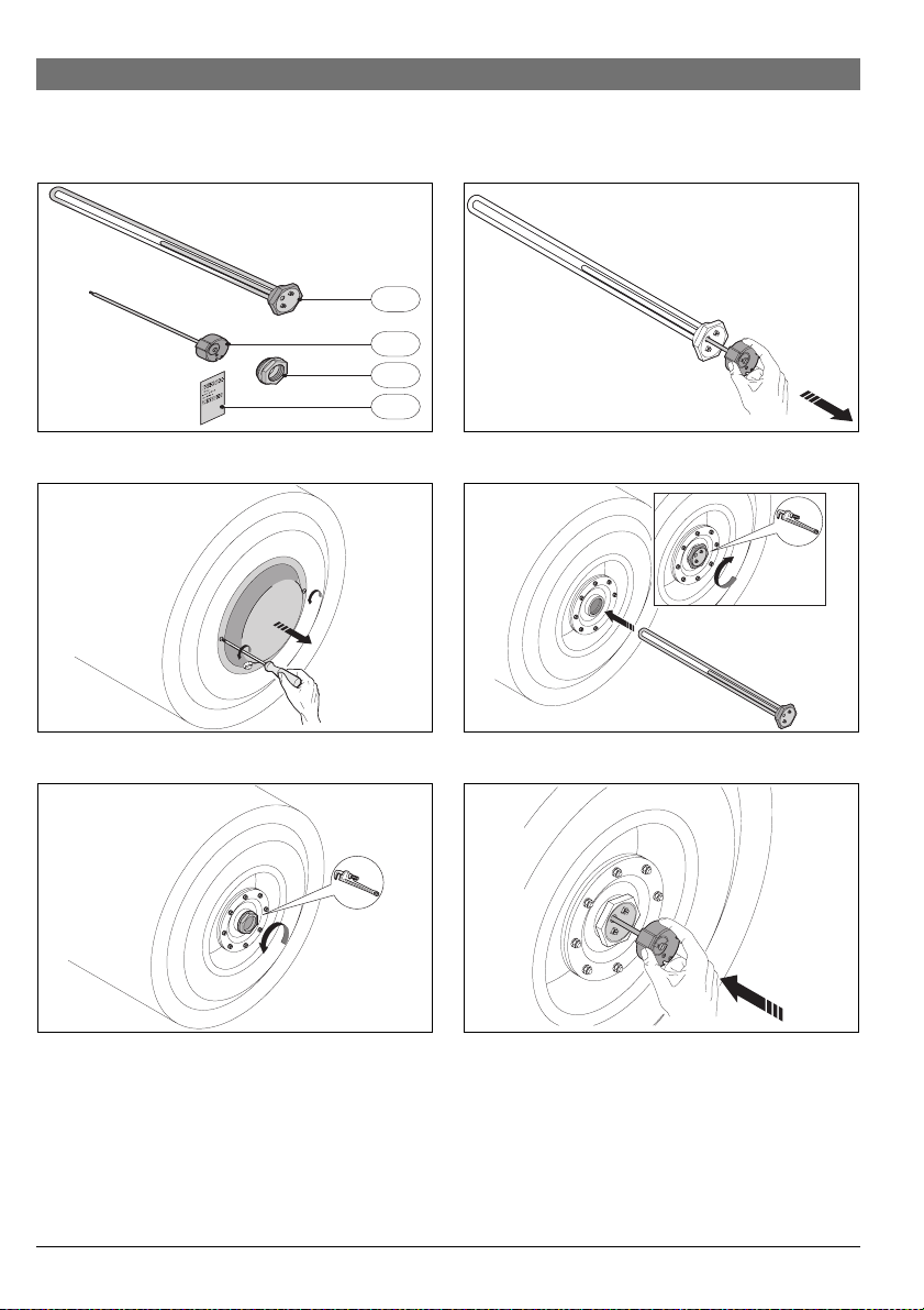
Installation
BThe following instructions are for the
installation of the electrical element for the
thermosyphon and respective electrical
connections. It is essential that all precautions
are taken to prevent electric shock hazard.
BMake sure that the electric power capacity in
the house is sufficient for the correct
operation of the heating element together
with the other household appliances already
in use.
BThe installation should only be carried out by
a qualified technician.
BThe installation should be carried out prior to
installation of tank on roof.
BThe electrical connection should be done in
accordance with AS/NZS 3000:2007.
BFirst connect the water and only afterwards
connect to the electrical supply.
BThe heating element should only be
connected to the electric current after the
installation has been concluded.
BBe aware that there is scalding risk and that
the roof may become slippery due to the hot
water which will escape from the tank when
removing the element.
BThe power supply must be protected by an
individual circuit breaker at the main electrical
supply switchboard and rated to suit the
booster size. The supply to the solar water
heater can be operated directly from the
switchboard or via a remotely mounted switch
or time clock as requested by the customer.
The heater must be provided with a suitable
means for disconnecting the power supply.
Maintenance
BInspection of the electrical connections and of
the heating element and thermostat set by a
specialised technician is strongly
recommended, at maximum intervals of 2
years.
Client information
BInform the client about the operation of the
heating element and its handling procedures.
BAdvise the client that no modifications or
repairs should be carried out by person other
than licensed technicians.
BInform the client that in the event that no hot
water is used during a significant period of
time and/or there is exposure to intense solar
radiation, the electricity supply should be
switched off.
BInform the client that in the event that hot
water is not used over a long period of time
and/ or there is exposure to intense solar
radiation (e.g. summer holidays), the tank may
reach temperatures higher than the safety
control temperature of the thermostat
incorporated in the heating element. In such
cases it is recommended that a qualified
technician be contacted in order to reset the
thermostat so that it starts working again.

6 720 644 138 (2011/09)TSS
Information on accessories | 5
2 Information on accessories
2.1 Use according to directives
This device complies with the provisions defined
in the European directives 2006/95/EC and
2004/108/EC .
2.2 Equipment supplied
ÆFigure 1, page 10:
1. Heating element with ring sealer
2. Thermostat
3. 1"¼ to 1"½ sleeve with 'ring sealer
4. Rating plate
2.3 Equipment required
•1x Drill
•1x 2,5 mm drill
•1x Philips screwdriver
•1x Terminal box
•1x 2,5 mm2electric cable
•1x 16 mm2ground wire

6 720 644 138 (2011/09) TSS
6| Information on accessories
2.4 Technical Information
2.5 Lightning arrestor
The conductive parts of the thermosyphon
system should be connected to a ground cable of
at least 16 mm2and to the voltage controller by
a company specialised in electricity.
If there is protective equipment against
lightening, the connection of the thermosyphon
system to the protective equipment should be
inspected by a technician specialised in
electricity.
Technical characteristics
Type of tank litre 300
Rated output Watt 3000
Warm-up time (15 °C - 50 °C) 3h48m
Voltage Vac 230/240
Frequency Hz 50
Electric current A12,5 (AU)
13,0 (NZ)
Section of electric cable to be installed mm22,5
Level of protection I
Type of protection IPX4
Thermostat
Range of selectable temperatures °C 10 - 70
Table 1

6 720 644 138 (2011/09)TSS
Installation | 7
3Installation
3.1 Assembly
BRemove the maintenance cap (ÆFig. 2).
BUnscrew the 1"½ pipe plug of the orifice of
the heating element by turning in a anti-
clockwise direction (ÆFig. 3).
BRemove the thermostat from the heating
element (ÆFig. 4).
BScrew the heating element in by turning in a
clockwise direction (ÆFig. 5).
BInsert the thermostat (ÆFig. 6).
BPass the electric cable through the sealing
gland (ÆFig. 7).
BConnect the power supply and grounding
connections to the thermostat and to the
electrical switchboard (ÆFig. 8).
CAUTION:
The installation, the electrical
connections, as well as the first
start-up are operations to be
carried out exclusively by
authorised installers.
DANGER: Electrical Protection!
BThe heating element should
have an independent
connection on the electrical
switchboard, protected by a
current relay and grounding.
WARNING: Damage to heating
elements!
BThe heating element should be
switched on after the system
has been filled.
CAUTION:
Never obstruct the bleeder of the
safety valve.
The relationship between the
power resistance and the volume
of the tank should a maximum of
10 W/l. Example: do not use a
3000W resistance in a 200 l tank.
Before installing the element it may
be necessary to apply a 1"¼ to 1"½
sleeve.
In such cases, the sleeve will be
supplied together with the
equipment.
Only the sleeve provided by the
manufacturer should be used.
NOTE:
The electrical cable is not provided
with the device. The cable should
be acquired by the qualified
technician. The electrical cable
should be appropriate for this type
of installation, namely with regard
to the intensity of the electric
current, voltage, resistance to
outdoor environments and length.
NOTE:
All the sections of the electrical
cable should be protected from
the outdoor environment.
Therefore, it is recommended to
protect them with a plastic tube or
other waterproof material.

6 720 644 138 (2011/09) TSS
8| Installation
BAdjust the thermostat to the desired
temperature at which the heating element is
switched off (ÆFig. 9, position 2).
BProceed in filling the tank with cold water
from the water supply, as indicated in the
thermosyphon installation instructions.
BSwitch on the electrical circuit breaker.
BAfter 4 hours check for leaks.
BTighten the maintenance cap again (Æ
Fig. 10).
BMake 2 extra holes with a diameter of 2,5 mm
on the maintenance cap (ÆFig. 11).
BApply the cap to those 2 holes with the screws
provided (ÆFig. 11).
BGlue on the rating plate of the heating
element provided with the equipment (Æ
Fig. 12).
3.2 Energy saving
In order to minimize the consumption of
electrical energy, the user may:
•using the breaker, manually, switch the power
supply on or off, taking into account if the
period is of low or high solar radiation.
The thermostat must be set to
60 °C, which corresponds to the
position of the pointer as shown in
Fig. 9.
NOTE:
The maintenance cap should be
fixed with 4 screws for enhanced
sealing and to prevent possible
leaks near the electrical
connections.
DANGER:
Scalding Risk
By touching the heating element.
When removing the element a
significant volume of hot water will
escape from the tank.

6 720 644 138 (2011/09)TSS
Maintenance | 9
4 Maintenance
Restarting the power supply
BPress the restart pin on the safety thermostat
(ÆFig. 9, position 1).
Draining the system
BSwitch off the electrical supply by using the
breaker.
BClose the water flow.
BOpen a hot water tap.
BOpen the safety valve purge.
Inspection of the electrical
connections and of the heating
element and thermostat set by a
specialised technician is strongly
recommended, at maximum
intervals of 2 years.
Ensure that the electrical capacity of
the house is sufficient for the
correct operation of the heating
element together with the other
appliances already in use.
The PTR valve should be periodically
bled to remove metal filing deposits
or other types of dirt and check if
the purge valve is not obstructed.
Check the need to restart the
heating system.
Be aware that there is scalding risk
and that the roof top might be
slippery.

6 720 644 138 (2011/09) TSS
10 | Annex
5 Annex
Fig. 1
Fig. 2
Fig. 3
Fig. 4
Fig. 5
Fig. 6
1
6720680229-08.1Av
4
2
3
6720680229-01.1Av
6720680229-05.1Av
6720680229-02.1Av
6720680229-06.1Av
6720680229-03.1Av

6 720 644 138 (2011/09)TSS
Annex | 11
Fig. 7
Fig. 8
Fig. 9
Fig. 10
Fig. 11
Fig. 12
6720680229-09.1Av
1.
1.
2. 2.
6720680229-07.1Av
°C
10
30
20 40
50
60
70
6720644138-01.1V
~60°C
1
2
6720680229-04.1Av
6720680229-12.1Av
6720680229-11.1Av

Australia
Robert Bosch (Australia) Pty Ltd
1555 Centre Rd
Clayton, VIC 31 8
Phone 1300 30 70 37
Fax 1300 30 70 38
www.bosch.com.au/hotwater
6720644138
Other manuals for TSS
2
Table of contents
Other Bosch Boiler Supplies manuals
Popular Boiler Supplies manuals by other brands

De Dietrich Thermique
De Dietrich Thermique AD252 Assembly instructions

Bryan Boilers
Bryan Boilers CFS-15-20-20D Specification sheet

Fröling
Fröling Lambdatronic H 3200 Service manual

Nibe
Nibe UKV 102 installation instructions

TiEmme
TiEmme 5535PF Instruction leaflet

Vaillant
Vaillant sensoNET VR 921 installation instructions