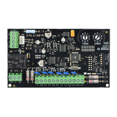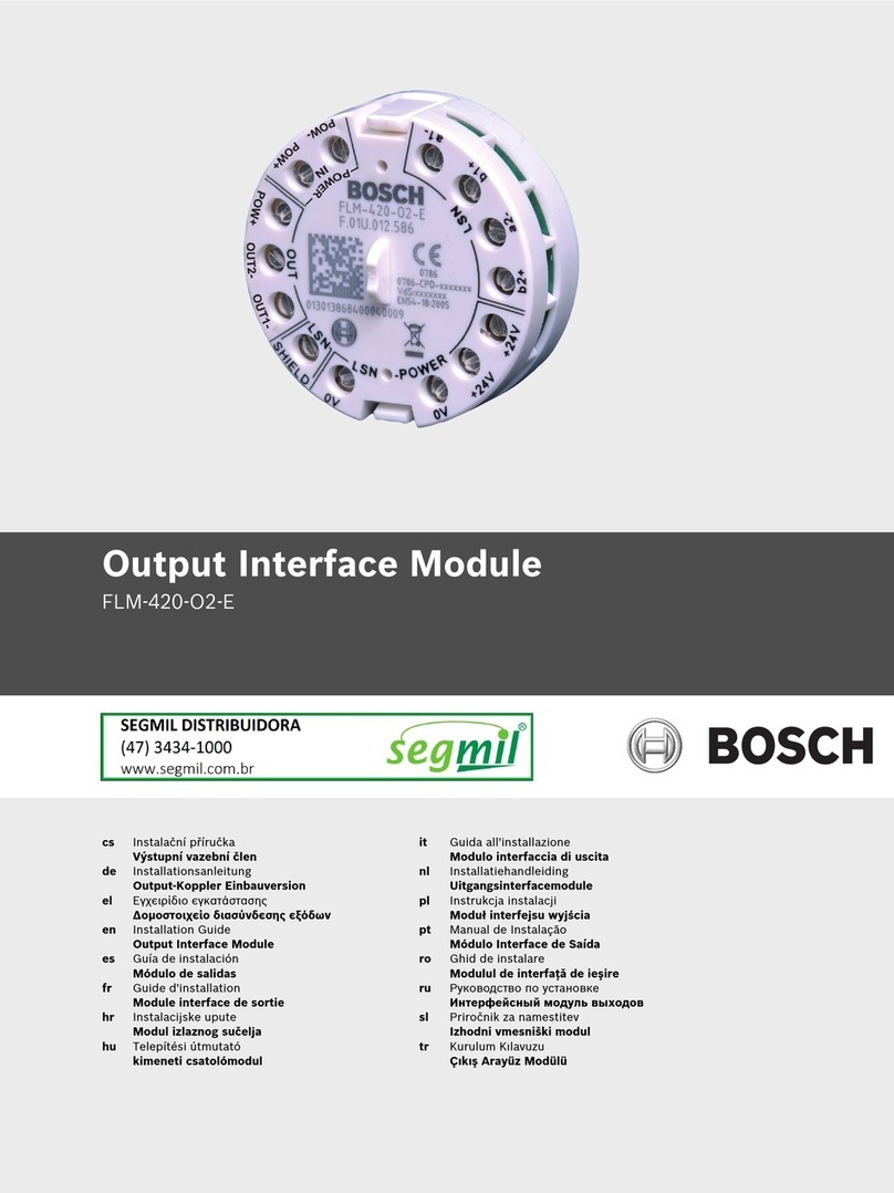
C900TTL-E |Installation Guide |
.
Bosch Security Systems, Inc. | 5/07 | 4998122718-02 3
Contents
Trademarks......................................................................2
UL Listings and Approvals...........................................2
1.0 Introduction.......................................................5
2.0 Installation .........................................................5
2.1 Mounting .............................................................6
2.1.1 Using the Optional Mounting Plate .................6
2.1.2 Attaching the Module to the Enclosure
Door .....................................................................7
2.1.3 Mounting in a Separate Enclosure ...................7
2.2 Wiring ..................................................................8
2.3 Input/Output Functions.....................................9
2.3.1 Inputs ...................................................................9
2.3.2 Outputs ................................................................9
2.4 Power Terminal Strip.......................................10
2.5 Phone Connections ..........................................10
2.6 Ethernet Connections.......................................10
3.0 C900TTL-E Setup ...........................................11
3.1 Setting the DIP Switches..................................11
3.2 LEDs ..................................................................13
3.2.1 Dialer LED........................................................13
3.2.2 System LED ......................................................14
3.2.3 Ethernet/Serial Status LEDs............................14
3.3 Fallback Mode ..................................................15
3.4 Dialer Interaction..............................................15
4.0 IP Address Configuration Setup
Instructions ......................................................16
4.1 Factory Programmed Default IP Address......16
4.2 Identifying the MAC Hardware Address ......16
4.3 Obtaining an IP Address .................................16
4.4 Using ARP.EXE to Assign an Initial IP
Address ..............................................................17
4.4.1 ARP Command Usage.....................................17
4.5 Using Telnet to Finish the Configuration ......18
4.5.1 Using Windows 98 Telnet ...............................18
4.5.2 Using Windows2000 or Windows XP
Telnet .................................................................22
4.6 Enabling Dynamic Host Configuration
Protocol (DHCP) ..............................................23
5.0 C900TTL-E Implementation of Anti-
Substitution Protection .................................23
6.0 UL Standard 1610 Intrusion System
Installations......................................................24
6.1 Protected Premises Control Panel without
Digital Dialer Backup.......................................24
6.1.1 C900TTL-E and Generic Control Panel in
Separate Enclosures..........................................24
6.1.2 Setting the DIP Switch.....................................27
6.2 Protected Premises Control Panel with
Digital Dialer Backup ...................................... 28
6.2.1 C900TTL-E and Generic Control Panel in
Separate Enclosures ......................................... 29
6.2.2 Setting the DIP Switch..................................... 29
7.0 UL Standard 864 for Fire System
Installations..................................................... 30
7.1 Installation at the Protected Premises............ 30
7.1.1 C900TTL-E and Generic Control Panel in
Separate Enclosures. ........................................ 30
7.1.2 Setting the DIP Switch..................................... 31
8.0 Specifications.................................................. 31
Appendix A: C900TTL-E Compatible Data
Formats............................................................. 31
Figures
Figure 1: C900TTL-E Location of Major Features ..... 5
Figure 2: Mounting the C900TTL-E on the
Optional Plate Mount .................................... 6
Figure 3: Attaching the Enclosure Door ...................... 7
Figure 4: C900TTL-E in AE2 Enclosure...................... 7
Figure 5: Wiring the C900TTL-E to a DS7400Xi
in the Same Enclosure ................................... 8
Figure 6: C900TTL-E Input, Output, and Power ....... 9
Figure 7: Telephone Line and Control Panel
RF-11 Phone Jack Wiring............................ 10
Figure 8: Ethernet Connector Pinouts........................ 10
Figure 9: C900TTL-E DIP Switches........................... 11
Figure 10:C900TTL-E LED locations........................ 13
Figure 11:Example MAC Address Label .................. 16
Figure 12:ARP Syntax ............................................... 17
Figure 13:Result of arp –g Command .................... 18
Figure 14:Setting Values in a Telnet Session............. 20
Figure 15:C900TTL-E Encryption.............................. 21
Figure 16:C900TTL-E and Generic Control Panel
in Separate Enclosures ComponentLocations
(UL Standard 1610, No Telephone Line)
(UL Standard 864)........................................ 25
Figure 17:Control Panel Connection Sequence........ 26


