manuals.online logo
Brands
  1. Home
  2. •
  3. Brands
  4. •
  5. Bosch
  6. •
  7. Security Sensor
  8. •
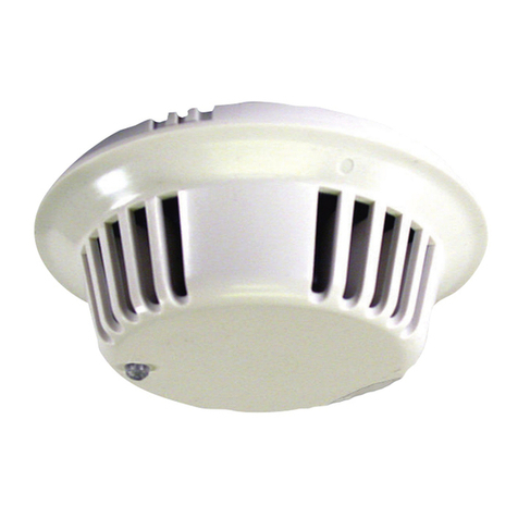
  9. Bosch DS1103i User manual

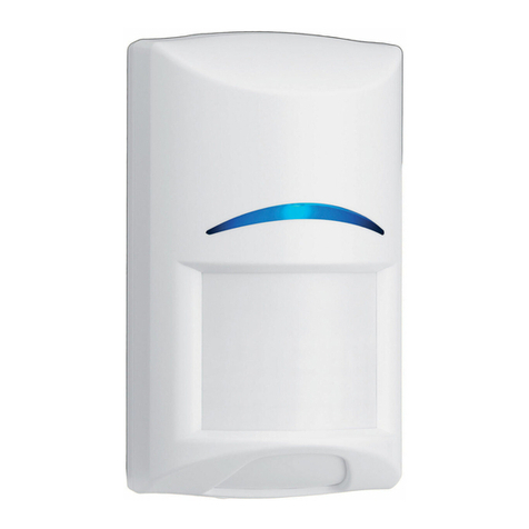
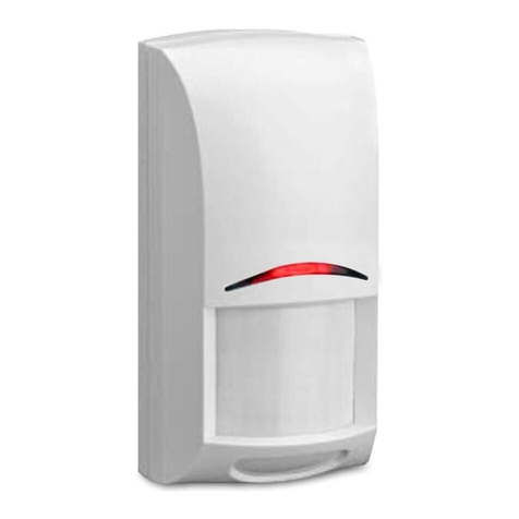
Bosch DS1103i User manual

Installation Instructions
for the
DS1103i Flush Mount
Glass Breakage Detector
1.0 Specifications
•Coverage: 25 ft. (7.6 m) maximum to farthest point of glass being
protected. For glass sizes over 12" by 12" (0.3 m by 0.3 m); types of
1/4" (0.64 cm) Plate, Tempered, Laminated, and Wired glass; and 1/8"
(0.32 cm) Plate glass (DSB).
•Mounting: Flush mount on the ceiling, on an opposite wall, or on an
adjacent wall.
•Input Power: 12 VDC (9 VDC min. to 15 VDC max.), 21 mA nominal
@ 12 VDC (26 mA max. in LED latch mode).
•Standby Power: Connect to power sources capable of supplying
standby power of 21 mA-H for each hour of required standby time.
Four hour minimum standby time required for U L Certificated
installations.
•Alarm Relay: Normally Closed reed relay (NC/C). Contacts rated
3.5 Watts, 125 mA @ 28 VDC for DC resistive loads. Protected by a
4.7 ohm resistor in the common “C” leg.
•Operating Temperature: -20° to +120°F (-29° to +49°C).
For U L
Certificated installations, the temperature range is +32° to +120°F
(0° to +49°C).
•Enclosure: 4.8” H, 3.25” W, 0.5” D (12 cm H, 8.3 cm W, 1.3 cm D).
When flush mounted: 4.8” H, 3.25” W, 0.25” D (12 cm H, 8.3 cm W,
0.625 cm D).
•Accessories: DS1110i Glass Breakage Tester.
2.0 Installation Considerations
NOTE: Always pre-test the detector’s location using the DS1110i
Glass Breakage Tester.
•Do Not…
…Mount the detector with obstructions between the glass being
protected and the detector.
…Mount on the same wall as the glass being protected.
…Mount the detector closer than 5 ft. (1.5 m) to the wall that
the glass being protected is on, or any hard, sound reflecting
surface.
…Mount closer than 2 ft. (0.6 m) to heating or cooling outlets;
mount as far away as possible. If drafts from these outlets
blow on the detector, select a different location for the
detector. Use the environmental test (see Section 4) to
verify good installation locations.
…Install on 24-hour protection circuits.
•Remember…
…The best mounting location is 10 to 20 ft. (3 to 6 m) from the glass, in-
line with the glass’s center, and on the ceiling or opposite wall of the
glass being protected. Do not exceed maximum range.
…The detector should be within ±30° of the center of the glass to be
protected.
…Range will be reduced in areas that are acoustically soft. This may be
due to carpeting, drapes, plants, or other sound absorbing materials.
The DS1110i Glass Breakage Tester should be used to verify range in
all installations.
…Glass breakage detectors are intended only as perimeter protection
devices. They should always be backed up with motion sensors.
…Glass breakage detectors are designed to detect the breakage of
framed glass and may not detect such things as bullet holes,
spontaneous breakage of glass (with no impact), and removal of
glass.
•Maximum range:
The maximum detection range is 25 ft. (7.6 m) from the farthest
corner, for glass sizes 12" by 12" (0.3 m by 0.3 m) and larger.
Hint: Tie a 25 ft. (7.6 m) string to the detector. The string should be able to
touch every part of the glass being protected. If any part of the glass
can not be touched by the string, it is outside of the detector’s
coverage and additional detectors should be used.
3.0 Selecting a Mounting Location
Opposite Wall Mounting
• Mount the detector where there are
no objects between itself and the
glass.
• Do not mount the detector closer
than 5 ft. (1.5 m) to the wall that the
glass being protected is on, or any
hard, sound reflecting surface.
• The detector should be within ±30°
of the center of the glass to be
protected (line B in Figure A).
• Make sure the detector is no farther than 25 ft. (7.6 m) from any corner
of the glass (line A in Figure A).
Ceiling Mounting
• The recommended location is half
the distance between the glass and
its opposite wall or 2/3 of the rated
range, whichever is smaller.
• Mount the detector where there are
no objects between itself and the
glass.
• Mounting to drop ceiling tiles is
acceptable.
• Do not mount the detector closer than 5 ft. (1.5 m) to the wall that the
glass being protected is on, or any hard, sound reflecting surface.
• Make sure the detector is no farther than 25 ft. (7.6 m) from any corner
of the glass (line A in Figure B).
• The detector should be within ±30° of the center of the glass to be
protected (line B in Figure B).
Adjacent Wall Mounting (not preferred)
• Mount the detector where there are
no objects between itself and the
glass.
• Do not mount the detector closer than
5 ft. (1.5 m) to the wall that the glass
being protected is on, or any hard,
sound reflecting surface.
• Make sure the detector is no farther
than 25 ft. (7.6 m) from the farthest
corner of the glass (line A in Figure C).
Multiple Detectors
•In some installations, multiple
detectors must be used to protect
larger glass.
•As a general rule, if the glass is
wider than 20 ft. (6.1 m), multiple
detectors should be used.
• Place each detector in-line with the
center of each 20 ft. (6.1 m) section of glass.
• Space the detectors evenly across the glass, but no farther than 20 ft.
(6.1 m) apart (line B in Figure D).
• Do not mount the detector closer than 5 ft. (1.5 m) to the wall that the
glass being protected is on, or any hard, sound reflecting surface.
• Make sure each detector is no farther than 25 ft. (7.6 m) from any corner
of its 20 ft. (6.1 m) section (lines A in Figure D).
BA
Figure A
B
A
Figure B
A
Figure C
A
A
Figure D
B
© 2004 Bosch Security Systems
130 Perinton Parkway, Fairport, New York, USA 14450-9199
Customer Service: (800) 289-0096; Technical Support: (888) 886-6189
02/04
DS1103i Installation Instructions
P/N: 28278G Page 2
4.0 Testing
Testing the Location
• Temporarily mount the detector using 2-
sided tape.
• Power the detector using a 9 Volt battery.
• The detector will enter the test mode, for
five minutes, as soon as power is applied.
The detector will indicate that it is in the test
mode by flashing the LED for 10 seconds.
At the end of five minutes the detector will
flash the LED again for 10 seconds to
indicate the test period is over. The test
mode can be restarted at any time by
powering the unit off and then on or by placing a magnet over the reed
switch (can be done with cover in place). Placing a magnet over the
reed switch when the unit is in the test mode will terminate the test.
NOTE: All testing should be done with the detector’s cover in place.
TEST #1: ENVIRONMENTAL TEST
Remember: The detector must be in test mode to perform this
test.
During the 5 minute test mode, the LED will indicate low or high frequency
disturbances by flashing at specific rates. Occasional (random)
flashes of the LED are normal. To rule out random flashes affecting
this test, observe the LED for the full five minutes.
• Turn on all sources of noise (e.g. forced air blowers, air conditioners,
compressor motors, etc.).
• The LED will flash 5 times per second each time a low frequency
disturbance is detected. If the 5 flashes per second occur more than
once every 15 seconds or if the unit alarms, then do not mount in this
location.
• The LED will flash once each time a high frequency disturbance is
detected. If any flashes occur more than once every 15 seconds, do
not mount in this location.
Remember: If the detector happens to alarm during this test, the alarm
relay will activate as well.
NOTE: If disturbances exist while positioning the detector in-line with the
center of the window, then the detector may be moved within a
60° (±30°) arc of the window’s center.
TEST #2: RESPONSE TEST
Remember: The detector must
be in test mode to perform this
test.
This test should be performed using
the DS1110i Glass Breakage Tester.
The DS1110i produces a high
frequency tone designed to alarm the
unit to further verify proper location.
CAUTION: Don’t point the tester directly at your or anyone’s ear. Doing so
could damage hearing.
• Hold the DS1110i Glass Breakage Tester against the window being
tested and point it at the detector.
- If there are curtains or blinds covering the window, close them
over the Tester.
• Activate the Tester.
- Setting the Tester to automatic mode causes it to activate every 6
seconds. This will allow you to better observe the detector’s LED.
- For large windows, perform this test at different placements along
the window.
• The alarm/test LED and the alarm relay will activate for three
seconds if this is an acceptable detector placement.
NOTE: The low frequency response of the detector can be tested (while
still in the test mode) by opening a door about 1 inch and slamming
it shut. The detector should indicate an alarm.
TOP
Alarm/Test LED LED Latch
Jumper
Test Mode
Reed Switch
DS1110i Tester -
hold against window and
point at detector
If window
treatments are
installed,
operate tester
behind them
•During the last 20 seconds of the detector’s test mode, its LED will
pulse. To end the test mode before the 5 minute time-out period, place a
magnet over the reed switch (can be done with the cover in place).
5.0 Mounting and Setup
Mount the Detector
• After verifying an acceptable location, permanently
mount the detector with the screw(s) provided.
The DS1103i is designed to mount to a standard single
gang electrical box (not supplied). Mount the box and pull
wiring to the box before mounting the detector.
Recess Mounting Ring
The DS1103i may also be recess mounted without the use of a single
gang box by using the supplied recess mounting ring.
• Using the recess mount ring as a template, prepare an opening 1.875”
wide by 2.75” high (4.76 cm wide by 6.9 cm high) in the mounting
surface.
• Route wiring through opening and ring.
• Place the ring over the opening and bend the support tabs into the
opening and around the mounting surface so that the ring fits snug
against the wall.
• Connect wiring as shown below.
• Mount the detector to the ring using the supplied screws.
• If the mounting surface is too deep for the recess mount ring, mount the
ring with flathead screws using the upper and lower holes.
6.0 Install Wiring
CAUTION: ONLY APPLY POWER AFTER ALL
CONNECTIONSHAVEBEENMADEANDIN-
SPECTED.
NOTE: Do not coil excess wire inside the unit.
NOTE: For Canadian installations, install in
accordance with the Canadian Electrical Code.
Select LED Latching Mode
ON: The LED will latch on when the unit is alarmed and will
stay on until it is reset. Momentarily interrupt input power to
reset the LED.
OFF: The LED will not latch after an alarm.
NOTE: If the jumper is removed or missing, the LED will default to the OFF
position.
7.0 Setup and Testing
• Replace the detector’s cover and secure it with the screw provided,
then apply power.
• Re-test the unit with the DS1110i Glass Breakage Tester.
Automatic Sound Check
• This detector features Automatic Sound Check which allows the end
user to test the unit on a periodic basis. To perform the test, simply clap
your hands or create some other loud sound. When the detector hears
this sound the LED (but not the alarm relay) will activate. This feature
works in the normal operating mode and does not require that the
detector be in the test mode.
The DS1103i is protected by the following patents:
#5,450,061 and #5,438,317.
OnOff
1234
–+
Voltage In Alar
m
TOP
Cover Latch

Other Bosch Security Sensor manuals

Bosch ISC-CDL1-W15G User manual

Bosch

Bosch ISC-CDL1-W15G User manual

Bosch CRS-SWM-TA869 User manual

Bosch

Bosch CRS-SWM-TA869 User manual

Bosch 200 C Use and care manual

Bosch

Bosch 200 C Use and care manual

Bosch ISN-SM-50 User manual

Bosch

Bosch ISN-SM-50 User manual

Bosch ISC-SM-90 User manual

Bosch

Bosch ISC-SM-90 User manual

Bosch Truvo User manual

Bosch

Bosch Truvo User manual

Bosch ISA-WM-869 User manual

Bosch

Bosch ISA-WM-869 User manual

Bosch ISC-BPR2-WP12 User manual

Bosch

Bosch ISC-BPR2-WP12 User manual

Bosch DS432i-CHI User manual

Bosch

Bosch DS432i-CHI User manual

Bosch RF940E Series User manual

Bosch

Bosch RF940E Series User manual

Bosch FAA-420-RI-ROW User manual

Bosch

Bosch FAA-420-RI-ROW User manual

Bosch DS9360 User manual

Bosch

Bosch DS9360 User manual

Bosch FCP-O 500 User manual

Bosch

Bosch FCP-O 500 User manual

Bosch F220 User manual

Bosch

Bosch F220 User manual

Bosch Photobeam 3000 ISC-FPB1-W30DS User manual

Bosch

Bosch Photobeam 3000 ISC-FPB1-W30DS User manual

Bosch ISN-SM-50 User manual

Bosch

Bosch ISN-SM-50 User manual

Bosch DMF 10 Zoom User manual

Bosch

Bosch DMF 10 Zoom User manual

Bosch DS940 User manual

Bosch

Bosch DS940 User manual

Bosch ISN-SM-90 User manual

Bosch

Bosch ISN-SM-90 User manual

Bosch LTC 2210 Series User manual

Bosch

Bosch LTC 2210 Series User manual

Bosch ISM-BLD1 User manual

Bosch

Bosch ISM-BLD1 User manual

Bosch MS-LZS User manual

Bosch

Bosch MS-LZS User manual

Bosch AP1-P User manual

Bosch

Bosch AP1-P User manual

Bosch ISW-ZPR1-WP13 User manual

Bosch

Bosch ISW-ZPR1-WP13 User manual

Popular Security Sensor manuals by other brands

MTEC 300 Instrument manual

MTEC

MTEC 300 Instrument manual

Maxouttech RF-ROR-135S-319-NN manual

Maxouttech

Maxouttech RF-ROR-135S-319-NN manual

C.P. Electronics MWS6-KNX installation guide

C.P. Electronics

C.P. Electronics MWS6-KNX installation guide

Prostat PED-718 user manual

Prostat

Prostat PED-718 user manual

HIK VISION DS-PDP15P-EG2 user manual

HIK VISION

HIK VISION DS-PDP15P-EG2 user manual

Reflex Marine FROG-3 user manual

Reflex Marine

Reflex Marine FROG-3 user manual

C.P. Electronics MWS3A-AT-PRM installation guide

C.P. Electronics

C.P. Electronics MWS3A-AT-PRM installation guide

Paradox ENVY NVX80 quick start guide

Paradox

Paradox ENVY NVX80 quick start guide

Abus FUBW50100 quick start guide

Abus

Abus FUBW50100 quick start guide

Paradox Omnia OMN-PMD1 user manual

Paradox

Paradox Omnia OMN-PMD1 user manual

Multitech RBS3010NA0EBN0 user guide

Multitech

Multitech RBS3010NA0EBN0 user guide

Timeguard Sure Time STW360 Installation & operating instructions

Timeguard

Timeguard Sure Time STW360 Installation & operating instructions

North Light HJ9104 manual

North Light

North Light HJ9104 manual

HIK VISION DS-PD2-T10P-WEH1 quick start guide

HIK VISION

HIK VISION DS-PD2-T10P-WEH1 quick start guide

Abus Security-Center FU5130 installation guide

Abus

Abus Security-Center FU5130 installation guide

C.P. Electronics MWS1A-PRM-LV installation guide

C.P. Electronics

C.P. Electronics MWS1A-PRM-LV installation guide

C.P. Electronics MWS5-PRM-SA-C installation guide

C.P. Electronics

C.P. Electronics MWS5-PRM-SA-C installation guide

Green Brook Orion Range manual

Green Brook

Green Brook Orion Range manual

manuals.online logo
manuals.online logoBrands
  • About & Mission
  • Contact us
  • Privacy Policy
  • Terms and Conditions

Copyright 2025 Manuals.Online. All Rights Reserved.