manuals.online logo
Brands
  1. Home
  2. •
  3. Brands
  4. •
  5. Bosch
  6. •
  7. Security Sensor
  8. •
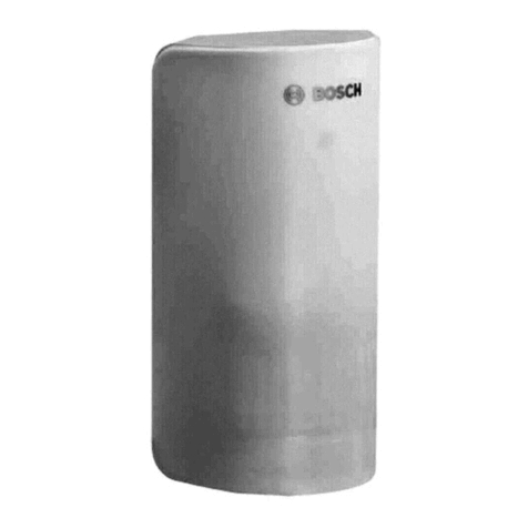
  9. Bosch ISN-SM-90 User manual

Bosch ISN-SM-90 User manual

A5Q00036139_a_-_- - 1 -
ISN-SM-90
en
Seismic detector
de
Körperschallmelder
Installation manual: A5Q00036139_a
_
-
_
-
Edition: 4.2009
A5Q00036139_a_-_- - 2 -
A5Q00036139_a_-_- - 3 -
+
en
Details for ordering
de
Bestellinformationen
ISN-SM-90 Seismic detector Körperschallmelder
ISN-GMX-P0 Mounting plate, complete Befestigungsplatte komplett
ISN-GMX-S1 Test transmitter Prüfsender
ISN-GMX-S5 External test transmitter Abgesetzter Prüfsender
ISN-GMX-W0 Wall recess set with cover Wandeinbauset mit Deckel
ISN-GMXW-G0 Watertight housing (IP65) Wasserdichtes Gehäuse IP65
ISN-GMX-B0 Floor box with cover Bodendose mit Deckel
ISN-GMX-P3S Swivel plate Schwenkplatte
ISN-GMX-P3Z Z-shaped swivel plate Schwenkplatte Z-Form
ISN-GMA-S6 Gusset shoe Aufsteckschuh
ISN-GMX-D7 Anti-drilling foil (set of 10) Bohrschutzfolien (10er Set)
ISN-SMS-W7 SensTool interface and software SensTool Interface und Software
GMXC2 Pipe connection sleeve 16 mm Rohranschlußmuffe 16 mm
GMYA7-AS Remote testing system for seismic detectors Fernprüfsystem für Körperschallmelder
GMYA7-A Alarm indication modul Alarmanzeigemodul
Relais in gezogenem Zustand (kein Alarm) gezeichnet
Relay shown in energised (non-alarm) condition
A5Q00036139_a_-_- - 4 -
en
1. Application
The ISN-MS-90 seismic detector provides reliable protection against
break-in attempts on safes, automatic cash dispensers, night deposit
boxes, lightweight safes (LWS), vaults and steel/concrete modular
strongrooms. Intelligent signal processing enables the level of
detection sensitivity to be custom-set, thereby reducing the risk of
false alarms. The removal monitoring system
2
Ewill detect the
forcible removal or opening of the detector.
Installation, programming and commissioning must be
performed by specialists.
For modular vaults, see Chapter 11.
2. Coverage area
The area monitored by the detector is referred to as the coverage
area
3
. It covers the area around the detector with an operating
radius indicated in
r
. Detectors should be positioned and spaced
apart, as indicated by (a), so that they cover the entire area to be
monitored.
Doors and joints impair transmission, so additional detectors must be
installed at these points. Tightly sealed corners and edges reduce the
range by 1/4. As a result, corners and edges on steel vaults must be
seamlessly welded. Incorrect positioning can reduce the coverage
area.
3. Attachment
There must be a direct connection between detector and
mounting base. Paint, varnish, dirt, silicone or similar
materials will impede this and must be removed.
A)In the case of steel walls
4
A, the detector should be mounted
directly on the flat, bare metal surface. Attach two M4x6 threads.
Use the drilling template as a positioning guide.
B) In the case of uneven or reinforced steel walls, the mounting plate
4
B(accessory ISN-GMX-P0) should be mounted using two fillet
welds. Mount the detector.
C) In the case of concrete walls
4
C, the mounting plate (accessory
ISN-GMX-P0) should be screwed in using a central metal plug.
Mount the detector.
D) Watertight housing
4
D(accessory* ISN-GMXW-G0).
E) For recessed mounting
4
E, screw the wall recess plate
(accessory ISN-GMX-W0) to the mould (1). Push the installation
conduit into the polystyrene. After filling the recess, remove the
polystyrene and the threaded bolt and cut the installation conduit
(2). Mount the detector and cover (3).
F) For floor mounting
4
F, create an appropriately sized recess, place
the floor box (accessory ISN-GMX-B0) inside and level it using two
metal plugs, a threaded bolt and lock nuts. Feed in the installation
conduits and fill the recess with liquid concrete. Place the detector
on a 2 mm distance plate, then attach the cover.
G)
Swivel plate (
4
G
) (accessory
*
ISN-GMX-P3S/ISN-GMX-PZ) including
adapter.
H) Mounting with a gusset shoe (
4
H) (accessory*ISN-GMA-S6).
* The installation instructions are supplied with the accessory.
4. Accessories
ISN-GMX-D7 Anti-drilling foil
Glue the foil to the inside of the cover
5
Cand connect the cable to
terminal
2
Dinstead of the jumper.
ISN-GMX-S1 Test transmitter
6
Screw in the test transmitter and connect the cables
2
C(M4x6 mm
thread).
ISN-GMS-W7 SensTool (terminal
2
F)
The software enables:
- Settings to be made for the application, impact sensitivity, digital
filters, polarity of TEST, REMOTE and alarm relay inputs, and
temperature monitoring
- Detector signals to be evaluated
- Results to be saved
5. Mounting the detector
Carefully open the detector
5
Aand screw it to the prepared
mounting base using two screws
5
B. Wire the connection cables to
terminal
2
Has shown in diagram
7
and attach a cable grip
2
I.
Connect the accessories and program the detector.
en
6. Programming
Application setting
2
G
Make the mounting base and operating radius settings.
The specified operating radius applies to attack with an oxygen lance;
if attacked with a mechanical tool (e.g. a drill) the value may be as
much as three times higher. The specified operating radius is a
guideline which is heavily influenced by the characteristics of the
substrate.
Operating
radius
r
Mode Fixed Fixed Fixed
USER MODE
Steel -- 2 m 1,5 m 1
*
/ 1,5 / 2 m
LWS -- -- -- 1,5 / 2 m
Concrete 4 m -- -- 2,5 / 4 / 5 m
*
Factory setting in USER MODE. Change with SensTool.
Sensitivity
7
(terminal 7)
Only apply for a short time. Any reduction in sensitivity must
comply with applicable regulations (e.g. VdS in Germany). )
Factory setting: Low active
Sensitivity is reduced to 1/8 for the duration of the remote signal.
Application: Prevention of alarm triggering where loud functional
noises prevail.
Test input
7
(terminal 4)
The ISN-GMX-S1 test transmitter
6
is activated via the test input. If
the detector is functioning correctly, it will trigger an alarm (trigger time
<3 s). Factory setting: Low active
7. LED display
The red LED
2
Bflashes during commissioning and initialisation. In
the event of an alarm, the LED lights up for approx. 2.5 s.
8. Commissioning
- Switch on voltage - Wait 30 s - Detector is ready for operation.
- Functional check: Trigger an alarm to test (e.g. scratch with a
screwdriver or switch on the test transmitter).
- Check for interference using SensTool or a measuring instrument
(Ri 20 k) at terminal 1 (0 V) and TP
2
Afor the analog integrator
signal: - Quiescent level ......................................... 0 V
- Integration start......................................... 1 V
- Alarm threshold (w/o load)........................ 3 V
- Carefully close the cover and screw it in place.
9. Maintenance
The function of the detector and its mounting should be checked at
least once a year.
10. Technical data
Supply voltage (nom. 12 VDC) ............................Vcc = 8 to 16 VDC
Current consumption (at 12 VDC, quiescent)................ Ityp. = 3 mA
Alarm condition ......................................................... Imax. = 5 mA
Alarm output, terminals 14+15:
Semiconductor relay.......................Opens on alarm + low voltage
Contact load...................................... 30 VDC/100 mA, ohmic load
Series resistance .................................................................. <45 
Alarm holding time ..................................................................2,5 s
Electronic alarm output, terminal 12:
Open collector.........................................................Alarm = 0 VDC
Short circuit strength........................................................ 16 VDC
Sabotage surveillance:
Tamper, terminals 10+11................................................................
Microswitch, cover + floor ...................... Opens on sabotage
Contact load .................................................30 VDC/100 mA
Anti-drilling foil in cover.....................................Sabotage ÖAlarm
Test input, terminal 4 ............................. Low <1,5 V/High >3,5 VDC
Remote input, terminal 7.................. Low <1,5 V/High >3,5 VDC
Operating temperature...........................................-40º to +70ºC
Storage temperature..............................................-40º to +70ºC
Air humidity (EN 60721), non-condensing .........................<95%
Approvals........................See type plate (
5
D) on housing cover
A5Q00036139_a_-_- - 5 -
en
11. Modular vaults
Applies for the following module dimensions:
Thickness from 100 to 400 mm
Width up to 1000 mm
Length up to 6500 mm
Modules with detector arrangement
1 2 3 4 5 1 2 3 4 5 . . . .
Corner joints between walls
seamlessly welded
Always 1 detector on
doors
Strict compliance with the following principles is vital when using
seismic detectors on modular vaults made from steel and
concrete:
1. One detector for a maximum of 5 wall modules; the detector
must be mounted on the middle module.
2. In addition to being bolted together, all joints between
modules must be welded every 400 500 mm with a 30 
40 mm seam.
3. Corner joints between wall modules must be seamlessly
welded if the coverage area is to extend beyond the corners.
4. In the case of wall modules equipped with detectors, the
immediately adjoining floor and/or ceiling modules can be
included in the coverage area if the corresponding butt joints
are seamlessly welded.
5. When building vaults using modules of varying thickness, the
butt joints must be seamlessly welded.
6. Avoid mounting detectors on modules to which guide rails for
cassette transport lifts, ventilators or other mechanical
equipment are attached.
7. Always equip modules which have a pay-in/withdrawal slot
with a detector; this will also be able to monitor the adjacent
modules.
8. All doors must always be equipped with a detector.
9. Programming:
Application setting
Max. 5 modules Concrete: 4 m
Doors Steel: 2 m
de
1. Anwendung
Der Körperschallmelder ISN-MS-90 erkennt zuverlässig
Aufbruchsversuche bei Safes, Geldautomaten, Nachttresoren,
Leichtbausafes (LWS), Stahlkammern und modularen
Tresorräumen aus Stahl oder Beton. Die intelligente
Signalverarbeitung erlaubt eine individuelle Einstellung der
Detektionsempfindlichkeit und somit eine hohe Sicherheit gegen
Falschalarm. Die Abreissüberwachung
2
Eerkennt eine
gewaltsame Entfernung oder Öffnung des Melders.
Die Montage, Programmierung und Inbetriebnahme
muss durch Fachpersonen erfolgen.
Für Elementtresore gilt Kapitel 11.
2. Wirkbereich
Die vom Melder überwachte Fläche wird als Wirkbereich
3
bezeichnet. Dieser breitet sich kreisförmig vom Melder mit dem
Wirkradius
r
aus. Die Positionierung der Melder und den Abstand
(a) so wählen, dass die gesamte zu überwachende Fläche
abgedeckt wird.
An Türen bzw. Fugen erfolgt keine sichere Übertragung, deshalb
zusätzliche Melder installieren. Gut verbundene Ecken und
Kanten reduzieren die Reichweite jeweils um 1/4. Deshalb
müssen Ecken und Kanten bei Stahltresoren durchgehend
verschweißt sein. Falsche Positionierung kann den Wirkbereich
reduzieren.
3. Befestigung
Zwischen Melder und Untergrund muss eine direkte
Verbindung sein. Farben, Lacke, Schmutz, Silikon o. Ä.
behindern diese und müssen entfernt werden.
A) Bei Stahlwänden
4
Aden Melder direkt auf die ebene, blanke
Metalloberfläche montieren. Zwei Gewinde M4x6 mm
anbringen. Positionierhilfe mit beigefügter Bohrschablone.
B) Bei unebenen oder gehärteten Stahlwänden die
Befestigungsplatte
4
B(Zubehör ISN-GMX-P0) mit zwei
Kehlnähten anschweissen. Melder montieren.
C) Bei Betonwänden
4
Cdie Befestigungsplatte (Zubehör ISN-
GMX-P0) mit einem zentralen Metalldübel anschrauben. Melder
montieren.
D) Wasserdichtes Gehäuse
4
D(Zubehör* ISN-GMXW-G0).
E) Bei Unterputzmontage
4
Edie Wandeinbauplatte (Zubehör
ISN-GMX-W0) an die Schalung schrauben (1). Installationsrohr
in den Schaumstoff einschieben. Nach dem Ausgiessen den
Schaumstoff und die Gewindestange entfernen, das
Installationsrohr abschneiden (2). Melder und Abdeckung
montieren (3).
F) Bei Bodenmontage
4
Fentsprechende Aussparung anbringen
und die Bodendose (Zubehör ISN-GMX-B0) mit zwei
Metalldübeln, Gewindestange und Kontermuttern auf
Bodenhöhe nivellieren. Installationsrohre einführen und
Aussparung mit dünnflüssigem Beton ausgiessen. Melder auf
2 mm Distanzscheibe, danach Abdeckung montieren.
G) Schwenkplatte
4
G(Zubehör* ISN-GMX-P3S/ISN-GMX-PZ)
inklusive Adapter.
H) Befestigung mit Aufsteckschuh
4
H(Zubehör*ISN-GMA-S6).
*Montageanleitung ist im Lieferumfang des Zubehörs.
4. Zubehör
ISN-GMX-D7 Bohrschutzfolie
Folie in die Deckelinnenseite kleben
5
Cund die Leitung an
Anschluss
2
Danstelle des Jumpers anschliessen.
ISN-GMX-S1 Prüfsender
6
Prüfsender festschrauben und Kabel
2
Canschliessen (Gewinde
M4x6 mm).
ISN-GMS-W7 SensTool (Anschluss
2
F)
Die Software ermöglicht:
- Einstellung von Anwendung, Schlagempfindlichkeit, Digitalfilter,
Polarität der Eingänge TEST, REMOTE und Alarmrelais,
Temperaturüberwachung
- Auswertung von Meldersignalen
- Speicherung von Ereignissen
A5Q00036139_a_-_- - 6 -
de
5. Melder montieren
Melder vorsichtig öffnen
5
Aund mit zwei Schrauben
5
Ban den
vorbereiteten Untergrund festschrauben. Anschlusskabel an
Klemme
2
Hentsprechend Plan
7
verdrahten und Zugentlastung
anbringen
2
I. Zubehör anschliessen und Melder programmieren.
6. Programmierung
Anwendungseinstellung
2
G
Der angegebene Wirkradius gilt für einen Angriff mit
Sauerstofflanze; bei Angriff mit mechanischem Werkzeug (z.B.
Bohrer) kann sich der Wert bis zum Dreifachen erhöhen. Der
angegeben Wirkradius ist ein Richtwerte, der stark von der
Beschaffenheit des Untergrunds beeinflusst wird.
Wirkradius
r
Modus fix fix fix
USER-MODE
Stahl -- 2 m 1,5 m 1
*
/ 1,5 / 2 m
LWS -- -- -- 1,5 / 2 m
Beton 4 m -- -- 2,5 / 4 / 5 m
*
Werkeinstellung bei USER MODE. Änderung mit SensTool.
Empfindlichkeit
7
(Klemme 7)
Nur kurzzeitig anwenden. Die Reduzierung der
Empfindlichkeit muss in Übereinstimmung mit den
geltenden Vorschriften erfolgen. (z. B. VdS)
Werkeinstellung=Low aktiv
Die Empfindlichkeit wird für die Dauer des Remote Signals auf 1/8
reduziert. Anwendung: Verhinderung von Alarmauslösung bei
starken funktionsbedingten Geräuschen.
Testeingang
7
(Klemme 4)
Über den Testeingang wird der Prüfsender ISN-GMX-S1
6
aktiviert. Bei korrekt funktionierendem Melder, löst dieser einen
Alarm aus (Auslösezeit <3 s). Werkeinstellung: Low aktiv
7. LED Anzeige
Die rote LED
2
Bblinkt während der Inbetriebnahme und
Initialisierung. Bei Alarm leuchtet die LED für ca. 2,5 s.
8. Inbetriebnahme
- Spannung zuschalten - 30 s warten - Melder ist betriebsbereit.
- Funktionsprüfung: Zum Testen Alarm auslösen (z. B. mit
Schraubendreher kratzen oder Prüfsender einschalten).
- Überprüfen von Störeinflüssen mit SensTool oder
Messinstrument (Ri 20 k) an Klemme 1 (0 V) und TP
2
Afür
analoges Integrationssignal:
- Ruhepegel ............................................0 V
- Integrationsstart....................................1 V
- Alarmschwelle (unbelastet)...................3 V
- Deckel vorsichtig schliessen und anschrauben.
9. Wartung
Mindestens einmal jährlich auf Funktion und Befestigung prüfen.
10. Technische Daten
Speisespannung (nom. 12 VDC)................. Vcc = 8 bis 16 VDC
Stromaufnahme (bei 12 VDC Ruhe)........................ Ityp. = 3 mA
Alarmzustand ..................................................... Imax. = 5 mA
Alarmausgang, Klemmen 14+15:
Halbleiter-Relais.................öffnet bei Alarm + Unterspannung
Kontaktbelastung................. 30 VDC / 100 mA, ohmsche Last
Seriewiderstand............................................................. <45 
Alarmhaltezeit.................................................................. 2,5 s
Elektronischer Alarmausgang, Klemme 12:
Open Kollektor................................................. Alarm = 0 VDC
Kurzschlussfestigkeit.................................................16 VDC
Sabotageüberwachung:
Tamper, Klemmen 10+11........................................................
Mikroschalter, Deckel + Boden......... öffnet bei Sabotage
Kontaktbelastung................................. 30 VDC / 100 mA
Bohrschutzfolie im Deckel ......................... Sabotage ÖAlarm
Test Eingang, Klemme 4 ................ Low <1,5V / High >3,5 VDC
Remote Eingang, Klemme 7........... Low <1,5V / High >3,5 VDC
de
Betriebstemperatur ............................................. -40º bis +70º C
Lagertemperatur ................................................. -40º bis +70º C
Luftfeuchtigkeit (EN 60721) nicht betauend......................<95 %
Zulassungen .............. siehe Typenschild
5
Din Gehäusedeckel
11. Elementtresore
Gültig für folgende Abmessungen der Elemente:
Stärke von 100 mm bis 400 mm
Breite bis 1000 mm
Länge bis 6500 mm
Elemente mit Meldereinteilung
1 2 3 4 5 1 2 3 4 5 . . . .
Eckverbindung Wand/Wand
durchgehend verschweißen
Immer 1 Melder auf
Türen
Beim Einsatz des Körperschallmelders auf Elementtresore aus
Stahl und Betonmaterial sind folgende Grundsätze unbedingt zu
beachten und einzuhalten:
10. Ein Melder für jeweils maximal 5 Wandelemente, wobei der
Melder auf dem mittleren Element platziert wird.
11. Alle Fugen zwischen den Elementen müssen zusätzlich zu
einer Verschraubung punktuell alle 400 500 mm mit einer
30 40 mm langen Schweißnaht verschweißt sein.
12. Eckverbindungen bei Wandelementen müssen durchgehend
verschweißt werden, wenn der Wirkbereich über den Ecken
genutzt werden soll.
13. Bei Wandelementen mit bestückten Meldern kann das direkt
angrenzende Boden- und/oder Deckenelement in den
Wirkbereich miteinbezogen werden, wenn die entsprechende
Stossstelle durchgehend verschweißt wird.
14. Bei Mischbauweise, wo unterschiedliche Elementdicken
kombiniert werden, müssen die Stossstellen durchgehend
verschweißt werden.
15. Melderplatzierungen auf Elemente vermeiden, an denen
Führungsschienen von Kassetten-Transportlifts, Ventilatoren
oder andere mechanische Einrichtungen befestigt sind.
16. Elemente mit einer Ein- oder Ausgabeöffnung mit einem
Melder bestücken, wobei dieser auch die angrenzenden
Elemente überwachen kann.
17. Auf allen Türen einen eigenen Melder platzieren.
18. Programmierung:
Anwendungseinstellung
auf max. 5 Elementen Beton 4 m
auf Türen Stahl 2 m

Other Bosch Security Sensor manuals

Bosch Anatel Professional Series User manual

Bosch

Bosch Anatel Professional Series User manual

Bosch D-tect 150 User manual

Bosch

Bosch D-tect 150 User manual

Bosch FCP-500 User manual

Bosch

Bosch FCP-500 User manual

Bosch FMC-210-SM-G-R User manual

Bosch

Bosch FMC-210-SM-G-R User manual

Bosch GMS 120 Assembly instructions

Bosch

Bosch GMS 120 Assembly instructions

Bosch DS778 User manual

Bosch

Bosch DS778 User manual

Bosch ISN-AP1-T User manual

Bosch

Bosch ISN-AP1-T User manual

Bosch D-tect 150 Professional User manual

Bosch

Bosch D-tect 150 Professional User manual

Bosch D-tect 150 Professional User manual

Bosch

Bosch D-tect 150 Professional User manual

Bosch TriTech+ Professional ISC-PDL1-WAC30G User manual

Bosch

Bosch TriTech+ Professional ISC-PDL1-WAC30G User manual

Bosch IR LD 1.0 User manual

Bosch

Bosch IR LD 1.0 User manual

Bosch Door/window contact II Operator's manual

Bosch

Bosch Door/window contact II Operator's manual

Bosch Blue Line Q1 User manual

Bosch

Bosch Blue Line Q1 User manual

Bosch Blue Line Q1 User manual

Bosch

Bosch Blue Line Q1 User manual

Bosch ISC-BPR2-WP12 User manual

Bosch

Bosch ISC-BPR2-WP12 User manual

Bosch ISC-PPR1-WA16G User manual

Bosch

Bosch ISC-PPR1-WA16G User manual

Bosch ISC-BDL2-WP12 User manual

Bosch

Bosch ISC-BDL2-WP12 User manual

Bosch DS306E User manual

Bosch

Bosch DS306E User manual

Bosch DS940P User manual

Bosch

Bosch DS940P User manual

Bosch ISC-BPR2-W12 User manual

Bosch

Bosch ISC-BPR2-W12 User manual

Bosch ISM-BLD1 User manual

Bosch

Bosch ISM-BLD1 User manual

Bosch ISC-PDL1-W18G User manual

Bosch

Bosch ISC-PDL1-W18G User manual

Bosch WEU PDO 6 User manual

Bosch

Bosch WEU PDO 6 User manual

Bosch D-tect 150 User manual

Bosch

Bosch D-tect 150 User manual

Popular Security Sensor manuals by other brands

Schnierle SafeTrans user manual

Schnierle

Schnierle SafeTrans user manual

Dermalog FLC1 user guide

Dermalog

Dermalog FLC1 user guide

Sicor R5840X EOM WFG Use and maintenance instructions

Sicor

Sicor R5840X EOM WFG Use and maintenance instructions

LEGRAND 0 489 66 manual

LEGRAND

LEGRAND 0 489 66 manual

AFRISO Eurovac HV operating instructions

AFRISO

AFRISO Eurovac HV operating instructions

Optex RXC-DT-X5 installation instructions

Optex

Optex RXC-DT-X5 installation instructions

olympia electronics TC100N Operation manual

olympia electronics

olympia electronics TC100N Operation manual

merten INSTABUS ARGUS 220 Connect manual

merten

merten INSTABUS ARGUS 220 Connect manual

Vimar NEVE UP 09467 manual

Vimar

Vimar NEVE UP 09467 manual

Honeywell MultiPro manual

Honeywell

Honeywell MultiPro manual

Emos P56300 manual

Emos

Emos P56300 manual

Avidsen 127043 instructions

Avidsen

Avidsen 127043 instructions

SICK GTB6L Operating	 instruction

SICK

SICK GTB6L Operating instruction

ANDIG 5379 User handbook

ANDIG

ANDIG 5379 User handbook

Zeiss BSD4 instruction manual

Zeiss

Zeiss BSD4 instruction manual

Petzl GRIGRI2 manual

Petzl

Petzl GRIGRI2 manual

Apollo ORB-OH-13001-APO Product guide

Apollo

Apollo ORB-OH-13001-APO Product guide

Redwall LRP3020 Installation instruction

Redwall

Redwall LRP3020 Installation instruction

manuals.online logo
manuals.online logoBrands
  • About & Mission
  • Contact us
  • Privacy Policy
  • Terms and Conditions

Copyright 2025 Manuals.Online. All Rights Reserved.