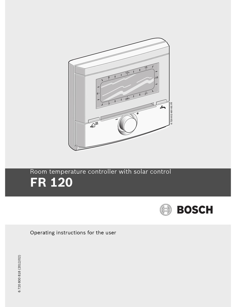
Bosch FR 120 User manual

Installation and operating instructions
Room temperature controller with solar control
FR 120
6 720 612 481-00.1R
6 720 800 817 (2012/02)

6 720 800 817 (2012/02)
2| Overview of controls and symbols
Overview of controls and symbols
Fig. 1 Controls
6 720 617 762-01.2O
3
34
1
menu info
1
2
35
6
7
8
4
912
h
15
18
21
24
h
3
6
advance advance

6 720 800 817 (2012/02)
Overview of controls and symbols | 3
Controls
1Turn rotary selector in +direction:
scroll menu/information up or increase
setting
Turn rotary selector in – direction:
scroll menu/information down or
decrease setting
Press rotary selector : open menu or
confirm setting/value or switch heating
circuit
2Operating mode selector for heating
circuits:
Automatic mode
Constant Comfort
Constant Economy
Constant Frost
3: Bring forward the next switching
point and the associated operating mode
= Comfort, = Economy, = Frost
for the heating circuit to the current time.
4Activate DHW heating immediately.
The DHW cylinder is heated to the
required temperature for 60 minutes or,
with combi boilers, comfort mode is
activated for 30 minutes.
5: Open/close menu
6: Show settings
7: Delete/reset setting
8: Return to next menu up
Tab. 1
menu
info
Symbols
Current room temperature
Flashing segment:
Current time (09:30 to 09:45)
Solid segments: time set for
operating mode = Comfort
today or DHW On (or ≥50 °C)
(1 segment = 15 min)
Empty segments: time set for
operating mode = Economy
today or DHW Off (or > 20 °C and
< 50 °C) (1 segment = 15 min)
No segments: time set for
operating mode = Frost today
or DHW ≤20 °C
(1 segment = 15 min)
Operating mode Comfort for
heating circuit
Operating mode Economy for
heating circuit
Operating mode Frost for
heating circuit
Automatic mode for heating
circuit
Holiday mode
Burner operation
Return to next menu up
Other display information (menu
points) are available. They can be
viewed by turning the rotary
selector .
Tab. 2
9
21
15
3

6 720 800 817 (2012/02)
4| Contents
Contents
1 Key to symbols and safety instructions . 6
1.1 Key to symbols . . . . . . . . . . . . . . . . 6
1.2 Safety instructions . . . . . . . . . . . . . 7
2 Technical data for the accessory item . . . 8
2.1 Standard delivery . . . . . . . . . . . . . . 9
2.2 Specification . . . . . . . . . . . . . . . . . . 9
2.3 Supplementary accessories . . . . . . . 9
2.4 Cleaning . . . . . . . . . . . . . . . . . . . . . 9
2.5 Sample system . . . . . . . . . . . . . . . 10
3 Installation (for contractors only) . . . . . 12
3.1 Installation . . . . . . . . . . . . . . . . . . . 12
3.1.1 Fitting the heating controller . . . . . 12
3.1.2 Fitting other accessories . . . . . . . . 13
3.1.3 Disposal . . . . . . . . . . . . . . . . . . . . . 13
3.2 Electrical connections . . . . . . . . . . 14
3.2.1 Connecting the BUS link . . . . . . . . 14
3.2.2 Connect the analogue 1-2-4
interface . . . . . . . . . . . . . . . . . . . . .15
4 Commissioning (contractors only) . . . . 16
5 Operation . . . . . . . . . . . . . . . . . . . . . . . . 18
5.1 Heating and DHW programs . . . . . 19
5.1.1 General . . . . . . . . . . . . . . . . . . . . . 19
5.1.2 7-day program . . . . . . . . . . . . . . . . 19
5.1.3 Structure of programs . . . . . . . . . . 19
5.2 Display views and menu navigation 20
5.3 Setting programs . . . . . . . . . . . . . . 21
5.3.1 Changing an individual switching
point . . . . . . . . . . . . . . . . . . . . . . . .21
5.3.2 Deleting an individual switching
point . . . . . . . . . . . . . . . . . . . . . . . .23
5.3.3 Resetting an entire program
(overwriting with factory settings) 23
5.4 Resetting all settings
(for heating contractors only) . . . 24
5.5 Manually setting operating modes 25
5.5.1 Selecting the operating mode for
heating . . . . . . . . . . . . . . . . . . . . . 25
5.5.2 Advancing heating mode before the
programmed time (bringing forward
the next switching point) . . . . . . . 25
5.5.3 Changing DHW mode
(time-limited) . . . . . . . . . . . . . . . . 26
5.5.4 Holiday program . . . . . . . . . . . . . . 26
5.6 Changing the set room
temperature . . . . . . . . . . . . . . . . . 27
5.6.1 Permanently changing the set
room temperature . . . . . . . . . . . . 27
5.6.2 Changing the set room temperature
for a limited period . . . . . . . . . . . . 27
6 Adjusting the MAIN MENU . . . . . . . . . . . 28
6.1 Menu structure . . . . . . . . . . . . . . . 28
6.2 Heating program . . . . . . . . . . . . . . 31
6.2.1 Time programs for heating . . . . . . 31
6.2.2 Temperature levels for the
operating modes . . . . . . . . . . . . . 32
6.3 DHW program . . . . . . . . . . . . . . . . 32
6.3.1 Time program for DHW with
combi boiler . . . . . . . . . . . . . . . . . 33
6.3.2 Timer/temperature program for
DHW with DHW cylinder . . . . . . . . 34
6.3.3 Time program for DHW circulation
pump (only with DHW cylinder) . . 34
6.3.4 DHW parameters (only with DHW
cylinder) . . . . . . . . . . . . . . . . . . . . 35
6.3.5 Thermal disinfection of hot water
(with DHW cylinder only) . . . . . . . 36
6.4 General settings . . . . . . . . . . . . . . 37
6.4.1 Time and Date . . . . . . . . . . . . . . . . 37
6.4.2 Display formats . . . . . . . . . . . . . . . 37
6.4.3 Key lock . . . . . . . . . . . . . . . . . . . . . 37
6.4.4 Language . . . . . . . . . . . . . . . . . . . . 37
6.5 Solar settings . . . . . . . . . . . . . . . . 38
Chapters against a grey
background are intended for
installers. The pages concerned
are identified by a grey vertical bar
at the side of the page.
6 720 800 817 (2012/02)
Contents | 5
7 Viewing information . . . . . . . . . . . . . . . . 39
8 Menu settings INSTALLER SETTINGS
(for contractors only) . . . . . . . . . . . . . . . 42
8.1 Summary and settings of the
INSTALLER SETTINGS menu . . . . . 42
8.1.1 INSTALLER SETTINGS:
System configuration . . . . . . . . . . . 42
8.1.2 INSTALLER SETTINGS:
Heating parameters . . . . . . . . . . . . 43
8.1.3 INSTALLER SETTINGS:
Solar system config . . . . . . . . . . . . 43
8.1.4 INSTALLER SETTINGS:
Solar sys parameters . . . . . . . . . . . 43
8.1.5 INSTALLER SETTINGS:
Fault history . . . . . . . . . . . . . . . . . 44
8.1.6 INSTALLER SETTINGS:
Cust service address . . . . . . . . . . . 44
8.1.7 INSTALLER SETTINGS:
System info . . . . . . . . . . . . . . . . . . 44
8.2 Configuring the heating system . . . 45
8.3 Parameters for heating . . . . . . . . . . 46
8.4 Configuring the solar thermal
system . . . . . . . . . . . . . . . . . . . . . . 47
8.5 Parameters for solar thermal
system . . . . . . . . . . . . . . . . . . . . . . 47
8.5.1 Commissioning the solar thermal
system . . . . . . . . . . . . . . . . . . . . . . 48
8.5.2 Parameters for the standard solar
thermal system . . . . . . . . . . . . . . . 48
8.5.3 Parameters for solar optimisation . 49
8.6 Fault history . . . . . . . . . . . . . . . . . . 51
8.7 Viewing and entering the customer
service address . . . . . . . . . . . . . . . 51
8.8 Viewing system information . . . . . . 51
9 Troubleshooting . . . . . . . . . . . . . . . . . . . 52
9.1 Troubleshooting using the display
(for heating contractors only) . . . . 52
9.2 Troubleshooting without using
display . . . . . . . . . . . . . . . . . . . . . . 57
10 Energy saving tips . . . . . . . . . . . . . . . . . . 58
11 Environmental protection . . . . . . . . . . . . 59
12 Commissioning report for the heating
system . . . . . . . . . . . . . . . . . . . . . . . . . . . 60
13 Individual time program settings . . . . . 61
13.1 Heating program for the assigned
heating circuit . . . . . . . . . . . . . . . . 61
13.2 DHW program . . . . . . . . . . . . . . . . 62
13.3 DHW circulation program
(only with DHW cylinder) . . . . . . . 63
Index . . . . . . . . . . . . . . . . . . . . . . . . . . . 64

6 720 800 817 (2012/02)
6| Key to symbols and safety instructions
1 Key to symbols and safety instructions
1.1 Key to symbols
Warnings
Keywords at the start of a warning indicate the
type and seriousness of the ensuing risk if
measures to prevent the risk are not taken.
•NOTE indicates that material losses may
occur.
•CAUTION indicates that minor to medium
injury may occur.
•WARNING indicates that severe injury may
occur.
•DANGER indicates a risk to life.
Important information
Additional symbols
Conventions used in these for representing the
menu structure:
•Individual menu levels are separated by the
> symbol, e.g. Holiday > Start
•Parameters that can be set/selected on a
menu are marked with a bullet point • .
•The operation of control elements is indicated
by the symbol for the control:
–means turn rotary selector
–means press rotary selector
–means press and release menu key
–means press and release info key
–means press and release delete/reset
key
–means press and release menu up key
–means press and release advance
switching time key
–means press and release immediate
DHW key
Warnings in this document are
framed and identified by a warning
triangle printed against a grey
background.
If there is a danger due to
electricity, the exclamation mark in
the warning triangle is replaced by a
lightning symbol.
Important information where there
is no risk to people or property is
indicated with the adjacent symbol.
It is bordered by lines above and
below the text.
Symbol Explanation
BAction step
ÆCross-reference to other parts of
this document or to other
documents
•List/list entry
–List/list entry (second level)
Tab. 3
menu
info

6 720 800 817 (2012/02)
Key to symbols and safety instructions | 7
1.2 Safety instructions
BThese instructions must be observed to
ensure correct operation.
BInstall and commission the heating appliance
and all accessories in accordance with the
instructions provided.
BThis accessory must only be installed by
suitably qualified installers.
BOnly use these accessories in conjunction
with the heating appliances listed. Follow the
connection diagram!
BNever connect this accessory to the 220 to
240 V mains.
BPrior to the installation of this accessory:
Isolate the heating appliance and all other
BUS subscribers from the power supply
(220 to 240 V AC).
BFor wall mounting: never install this accessory
in wet areas.
BInstruct customers about the functions and
operation of the accessory.
BRisk of scalding during thermal disinfection:
Supervise short periods of operation with
water temperatures over 60 °C or fit a
thermostatic DHW mixer.
BWhen there is a risk of frost, leave the heating
appliance switched on and follow the frost
protection information.
Risk of damage due to operator error.
Incorrect operation can cause injury and/or
material damage.
BEnsure children do not operate this accessory
unsupervised or play with it.
BMake sure that only people who are capable of
operating this accessory properly have access
to it.

6 720 800 817 (2012/02)
8| Technical data for the accessory item
2 Technical data for the accessory item
•The controller has a power reserve sufficient
for at least 6 hours of operation. If the
controller is without power for a period longer
than the power reserve then the time and date
will be deleted. All other settings are saved.
Heating appliance
FR 120 with
BUS-enabled
Heatronic 3
FR 120 with Bosch
Heatronic
(analogue 1-2-4
interface)
Wall mounting X X
1 non-mixed heating circuit X X
HK 2 ... HK 10 via FR 10/ FR 120 X 1)
1) with IPM ...
Time/temperature level profile for associated heating
circuit
X X
Heat-up optimisation X X
DHW heating X
DHW heating via heating appliance with DHW heating
acc. to instantaneous water heater principle
XX 2)
2) controlled by the heating appliance
DHW heating via DHW cylinder on heating appliance X X 2)
DHW heating via DHW cylinder downstream of low loss
header
X
Thermal disinfection X
Time program for DHW heating X
Time program for DHW circulation pump X
Time/temperature level profile for DHW X
Solar thermal system X 3)
3) with ISM ...
Thermal disinfection of solar cylinder X 3)
Tab. 4 Operating characteristics of these controllers

6 720 800 817 (2012/02)
Technical data for the accessory item | 9
2.1 Standard delivery
Fig. 2 Standard delivery
1Controller top section
2Base for wall mounting
3Slide cover
4Installation and operating instructions
2.2 Specification
2.3 Supplementary accessories
See also the pricelist.
•IPM 1: Module for controlling one
mixed or one non-mixed heating circuit.
•IPM 2: Module for controlling up to two mixed
heating circuits. Controlling one non-mixed
heating circuit in the heating system is
possible.
•ISM 1: Module for controlling solar DHW
heating.
•FR 10: Room temperature controller without
heating program to extend the heating system
by one additional heating circuit (not
permissible in Germany).
2.4 Cleaning
BIf required, use a damp cloth to wipe the
controller casing. Never use aggressive or
acidic cleaning agents for this.
Dimensions Fig. 5, page 12
Rated voltage 10...24 V DC
Rated current
(excluding
illumination)
6 mA
Controller output 2-wire BUS
1-2-4 interface
Permiss. ambient
temp.
0 ... +50 °C
IP rating III
Protection class IP20
Tab. 5 Specification
2
4
1
3
6 720 613 058-01.1R
8

6 720 800 817 (2012/02)
10 | Technical data for the accessory item
2.5 Sample system
Fig. 3 FR 120 and combi boiler: Simplified system scheme (see technical guides for installation
illustration and further options)
230 V AC
VF
HW 6 720 800 003-01.1O
MF4
P4
M4
TB4
HK4HK5...HK10
M
MF3
P3
M3
TB3
HK3
M
IPM 2
FR 120
FK
FR 120FR 120FR 120
230 V AC
MF2
P2
M2
TB2
HK2
M
MF1
P1
M1
TB1
HK1
M
IPM 2
HP
230V/AC
FR 101) FR 101) FR 101)
T
1
T
2
KW
S...solar
TWM
230 V/AC
SP
ISM 1
ZW...
WW

6 720 800 817 (2012/02)
Technical data for the accessory item | 11
Fig. 4 FR 120 and heating appliance with DHW cylinder connection: Simplified system scheme (see
technical guides for installation illustration and further options)
Key to Fig. 3 and Fig. 4:
FR 10 Room temperature controller for
additional heating circuit
FR 120 Room temperature controller
FK Flat-plate collector
HK1...10 Heating circuits
HP Heating circuit pump
HW Low loss header
IPM 2 Module for two heating circuits
ISM 1 Module for solar DHW heating
KW Cold water connection
M1...10 Mixer motor
MF1...10 Flow temperature sensor, mixed
heating circuit
P1...10 Heating circuit circulation pump
PE Thermal disinfection pump
S...solar Solar cylinder
SF Cylinder temperature sensor (NTC)
SP Solar circuit pump
T1Collector temperature sensor
T2Cylinder temperature sensor, bottom
TB1...10 Temperature monitor
TWM Thermostatic DHW mixer (to protect
combi boiler against overheating)
VF Common flow temperature sensor
WW DHW connection
ZS... Heating appliance with cylinder
connection
ZW... Combi boiler
1) Option FR 10 or FR 120
230 V AC
VF
HW 6 720 800 003-02.1O
MF
4
P
4
M
4
TB
4
HK
4
HK
5
...HK
10
M
MF
3
P
3
M
3
TB
3
HK
3
M
IPM 2
FR 120
FK
FR 120FR 120FR 120
230 V AC
MF
2
P
2
M
2
TB
2
HK
2
M
MF
1
P
1
M
1
TB
1
HK
1
M
IPM 2
HP
230V/AC
FR 10
1)
FR 10
1)
FR 10
1)
T
1
T
2
KW
S...solar
230 V/AC
SP
PE
ISM 1
SF
ZS...
WW
ZP
TWM
T
WWKG

6 720 800 817 (2012/02)
12 | Installation (for contractors only)
3 Installation (for contractors only)
The detailed system scheme for installing the
hydraulic components and the associated control
devices can be found in the technical guides or
tender specifications.
3.1 Installation
3.1.1 Fitting the heating controller
The control quality of the controller is dependent
on where it is installed.
The installation location (= lead room) must be
suitable for controlling the associated heating
circuits.
BSelect the installation location.
Fig. 5
BRemove the top section and slide cover from
the base.
Fig. 6
BFit the base.
Fig. 7
BMake the electrical connections (ÆFig. 11 on
page 15 or 9 on page 14).
DANGER: Risk of electric shock!
BPrior to the installation of this
accessory:
Isolate the heating appliance and
all other BUS subscribers from the
power supply (220 to 240 V AC).
6 720 612 481-03.1R
0,3 m0,3 m
1,2 - 1,5 m
0,6 m
119 mm
134 mm
35 mm
The mounting surface on the wall
should be level.
1.
2.
3.
6 720 612 220-27.1J
6 720 645 340-07.1O
6 mm 3,5 mm6 mm

6 720 800 817 (2012/02)
Installation (for contractors only) | 13
BRefit top section and slide cover on base.
Fig. 8
3.1.2 Fitting other accessories
BFit accessories according to the legal
requirements and the installation instructions
supplied with them.
3.1.3 Disposal
BDispose of packaging in an environmentally
responsible manner.
BWhen replacing components, dispose of the
used components in an environmentally
responsible manner.
3.
2.
1.
6 720 612 220-06.1R

6 720 800 817 (2012/02)
14 | Installation (for contractors only)
3.2 Electrical connections
BUse electrical cable according to local codes
and requirements.
BRoute all LV cables/leads separately from
cables carrying 220 to 240 V or 380 to 415 V
to avoid inductive interference (minimum
separation 100 mm).
BIn case of external inductive interference,
shield the cables.
This ensures that the cables are shielded from
external interference (e.g. heavy current
cables, overhead wires, transformer stations,
radio and television set, amateur radio
stations, microwave ovens etc).
3.2.1 Connecting the BUS link
Permissible lead lengths from the BUS-enabled
Heatronic 3 to the controller:
BConnect the controller to a heating appliance
with BUS-enabled Heatronic 3.
Fig. 9 Controller connected to BUS-enabled
Heatronic 3.
Connection via BUS interface or
1-2-4 interface:
BTo achieve as even a radiator
temperature as possible,
connect the controller via the
2-wire BUS.
The flow temperature is only
heated to a level that allows the
required room temperature to be
reached. This demand-
dependent flow temperature
control is achieved through
longer pump run-on times,
allowing as low a flow
temperature as possible, and
therefore energy saving
operation. This type of control
offers the full range of setting
options and displayed
information.
BTo reduce the pump run-on time,
connect the controller via
1-2-4 interface.
Through the output control, the
boiler reacts quickly to changes
in room temperature. This type
of control reduces the range of
setting options and displayed
information. This classic type of
control is highly suitable for
combi boilers in apartments, for
example, because the displays in
these systems are extremely
convenient.
Lead length Cross-section
≤80 m 0.40 mm2
≤100 m 0.50 mm2
≤150 m 0.75 mm2
≤200 m 1.00 mm2
≤300 m 1.50 mm2
Tab. 6
FR 120
124BB
6 720 800 003-03.1O
ST 19
Heatronic 3
AF
BB

6 720 800 817 (2012/02)
Installation (for contractors only) | 15
Fig. 10 BUS links connected via branch box (A)
3.2.2 Connect the analogue 1-2-4 interface
Permissible lead lengths of FR 120 to the heating
appliance:
BConnect the controller to a heating appliance
with optional connections for analogue 1-2-4
interface (24 V DC).
Fig. 11 Controller connected via the analogue
1-2-4 interface.
If the BUS links feature different
cross-sections:
BConnect BUS links via a branch box.
B
2
BB
A
B
2
BB
B
2
BB
6 720 612 220-08.1J
100 mm 100 mm
Lead length Cross-section
≤20 m 0.75 mm2– 1.50 mm2
≤30 m 1.00 mm2– 1.50 mm2
≥30 m 1.50 mm2
Tab. 7
The third contact enables the
controller to recognise that it is not
connected via the BUS link but
instead via the analogue
1-2-4 interface.
6 720 800 003-04.1O
FR 120
124
124
124
124
DC 24V

6 720 800 817 (2012/02)
16 | Commissioning (contractors only)
4 Commissioning (contractors only)
For correct commissioning, it is essential that the
following steps are carried out in the order
shown.
1. Set the DIP switch on IPM 1 and IPM 2 in
accordance with the details in the instruc-
tions supplied.
2. Switch the system ON.
3. Program additional room temperature cont-
rollers FR 10 (not permissible in Germany)
or FR 120 in accordance with the details in
the manual supplied.
4. When commissioning for the first time or
after a complete reset (all settings have
been reset), you need to select the display
language:
–Turn to select the language and
press to confirm. (For how to
change the language Æchapter 6.4.4 on
page 37.)
5. If the power reserve has run out, set the time
and date as follows:
–Turn to select the hour and press
to confirm.
–Turn to select the minutes and
press to confirm.
–Turn to select the year and press
to confirm.
–Turn to select the month and press
to confirm.
–Turn to select the day and press
to confirm. (For how to change the
date and time Æchapter 6.4.1 on
page 37.)
6. Set the code for the heating circuit (only
FR 120 with BUS connection)
–If the controller is to control heating cir-
cuit HC1and DHW heating: Identification
CH circuit select code 1 with and
confirm with .
–If the controller is to control heating cir-
cuit HC2...10:
Identification CH circuit with
select a code between 2 and 10and con-
firm with .
7. During commissioning, automatic system
configuration starts immediately after entry
of the date and time.
–Wait for 60 seconds and then follow the
instructions displayed.
–If automatic system configuration does
not start of its own accord, start it from
the menu Æchapter 8.2 on page 45.
8. Switch off automatic Auto switch between
GMT - BST Æchapter 6.4.1 from page 37
9. Adjust other settings to suit the current sys-
tem, Æchapter 6 starting on page 28 and
chapter 8 starting on page 42.
10. Fill and vent the solar thermal system accor-
ding to its documentation and prepare it for
commissioning as described in chapter 8.4
on page 47.
11. Adjust other settings to suit the current solar
thermal system, Æchapter 8.5 starting on
page 47.
12. Commission the solar thermal system,
Æchapter 8.5.1 on page 48.
For each heating circuit, only one
FR 10 or FR 120 can be assigned
per code.
The functions of the controls and
the meanings of the symbols on the
display are explained on pages 2
and 3.

6 720 800 817 (2012/02)
Commissioning (contractors only) | 17
13. Inform the system user about the functions
and method of operation as follows:
–The contractor explains to the customer
how the heating appliance and controller
work and how to operate them.
–Explain to the user how to operate the
system on a day-to-day basis, e.g. time,
operating modes for the heating circuits,
DHW temperature, time programs for
heating circuits and DHW.
–Explain how to use the thermal disinfec-
tion function and the associated risk of
scalding.
–Hand all documents provided over to the
user.
14. Complete the commissioning report,
Æchapter 12 on page 60.

6 720 800 817 (2012/02)
18 | Operation
5 Operation
Introduction
With the FR 120 heating controller, you can
automatically control the room and DHW
temperatures with a heating and DHW program
created according to your own individual
requirements.
Fig. 12 Example of heating program
Once the controller is set to your personal
preferences, you hardly need the menus for
“everyday use”. Nevertheless, it is useful to be
familiar with basic navigation through the menus.
Therefore, you should read the whole of the
following sections 5.1 and 5.2 below and adjust a
heating or DHW program to your own
requirements as described in chapter .
Why not take the trouble – it will be worth your
while! The procedure for changing a switching
point will illustrate everything you need to know
about navigating through the menus and entering
settings. You can then make all other settings in
the same way with the aid of the information in
chapters 6 and 8.
The description of the menus reflects the
arrangement of the menu points in the heating
controller. The menu structure in chapter 6.1 and
the tables in chapters 7 and 8.1 show the entire
menu tree. They also provide details of the
setting ranges and factory settings for all
adjustable parameters. More information on the
menu points can be found in sections 6.2 to 6.5
for the user level, and sections 8.2 to 8.8 for the
contractor level.
The description of a menu points starts with its
menu path. That shows you how to reach the
menu point concerned by navigating through the
menus. The individual menu levels are separated
by symbol > , e.g. holiday > start.
Some menu points are dependent on others. In
such cases, a page reference directs you to a
description of the menu point on which it
depends. Make use of such page references to
other menu points. They will help you to
understand associated functions.
If the FR 120 is connected to the
heating appliance via the analogue
connection (1-2-4 interface), only
the heating program, the
parameters for central heating and
the controller-specific settings
(e.g. Time) are active. DHW, solar
and system-specific settings
(e.g. System info) are not available.
In this case, DHW can be switched
directly via the heating appliance.
The functions of the controls and the
meanings of the symbols on the
display are explained on pages 2
and 3.
[°C]
[t]
6 720 612 481-70.1J
The controller provides the option
of setting the required room
temperature for the operating mode
concerned.

6 720 800 817 (2012/02)
Operation | 19
5.1 Heating and DHW programs
5.1.1 General
The programs for heating and DHW enable you to
achieve maximum energy savings while still
enjoying optimum comfort in terms of room
temperature and availability of hot water. That is
achieved, for instance, by deactivating DHW
heating at times when nobody requires hot
water.
5.1.2 7-day program
The time program is set up so it repeats every
seven days. The program memory can store 6
switching times per day, i.e. a total of up to 42
switching times.
To simplify programming, you can set switching
times for groups of days as well as for individual
days.
The following groups of days are offered:
•All days
•Mon - Fri
•Sat + Sun
If, for example, you change and save a switching
time for menu point Mon - Fri, that change is
simultaneously applied to every day from
Monday to Friday.
5.1.3 Structure of programs
Programs for heating and DHW are always
structured in the same way. Up to six switching
points (switching times) can be specified. A
change of operating mode is specified for each
switching time. The specified operating mode
applies until changed by the next switching time.
Heating program
The heating program regulates the heating
operation. There are three modes for heating
operation:
•Comfort
•Economy
•Frost (frost protection)
For each of these operating modes, there is a set
room temperature stored in the heating
controller (Æchapter 5.6.1, page 27).
DHW program
The DHW program acts differently, subject to the
method of DHW heating:
•With combi boilers (boilers which produce hot
water instantaneously on demand), the DHW
program switches between the following
operating modes:
–On: if the eco button on the heating
appliance is not lit, hot water is available
very quickly on demand (comfort mode).
–Off: the built-in plate heat exchanger in the
heating appliance is not kept constantly
hot (eco mode); as a result energy is saved.
In eco mode, the hot tap has to be run for
a short while before the water becomes
hot.
•With boilers connected to a domestic hot
water cylinder, the hot water programme
specifies the desired water temperature
(specified temperature).
–If the temperature measured in the DHW
cylinder is below the set temperature, the
cylinder is reheated.
–Once the set temperature is reached (or
exceeded), cylinder reheating is stopped.

6 720 800 817 (2012/02)
20 | Operation
DHW circulation program
The DHW circulation program specifies when a
connected DHW circulation pump for domestic
hot water runs.
5.2 Display views and menu
navigation
The user interface of the FR 120 room
temperature-dependent heating controller is
implemented as a so-called "menu". Within that
menu, the various functions are arranged in a
hierarchical structure. For greater clarity, the
menu is subdivided into three sections (MAIN
MENU, INFO, INSTALLER SETTINGS). Each
section can be accessed by its own button. The
entire menu structure is shown in tabular form in
chapters 6.1, 7 and 8.1.
To navigate through the menu:
•Press to open MAIN MENU. From any
point within the MAIN MENU, press to
go back to the standard display.
•Press to open the INFO menu. From any
point within the INFO menu, press to go
back to the standard display.
•Hold down for at least 3 seconds to open
the INSTALLER SETTINGS menu. From any
point within the INSTALLER SETTINGS menu,
press to go back to the standard display.
•The selected menu point/parameter is
displayed in colours, i.e. white on
black.
•Arrows in the left margin indicate that there is
more information than can be shown on the
display at once. It can be viewed with .
•opens the submenu associated with the
selected menu point/parameter or activates
editing mode for the parameter (the
parameter setting starts flashing).
If the DHW program changes from a
higher to a lower temperature, the
water in the cylinder will not
immediately cool to the lower
temperature, i.e. water at a higher
temperature will continue to be
available for some time. However,
the cylinder will not be reheated
until the temperature falls below
the new set temperature.
menu
menu
info
info
menu
menu
i
n
f
o
inverse
Other manuals for FR 120
1
Table of contents
Other Bosch Temperature Controllers manuals

Bosch
Bosch Junkers NTC 10K User manual

Bosch
Bosch FR 120 Instruction Manual

Bosch
Bosch FR 100 Installation guide

Bosch
Bosch FW 100 User manual

Bosch
Bosch YPRM66XB User manual

Bosch
Bosch CRC200 User manual

Bosch
Bosch HEZ39050 User manual

Bosch
Bosch FB 100 User manual

Bosch
Bosch 8733951033 User manual

Bosch
Bosch C1210ES Reference manual