manuals.online logo
Brands
  1. Home
  2. •
  3. Brands
  4. •
  5. Bretford
  6. •
  7. Indoor Furnishing
  8. •
  9. Bretford EC7000 User manual

Bretford EC7000 User manual

Other Bretford Indoor Furnishing manuals

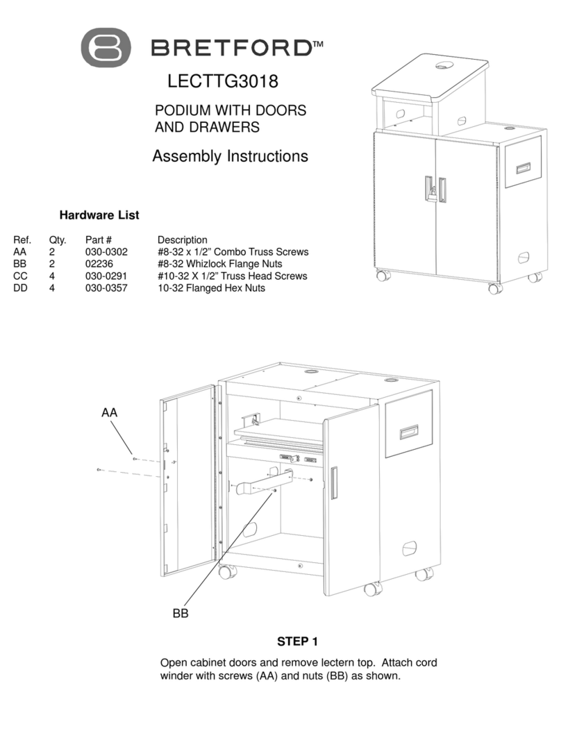
Bretford LECTTG3018 User manual

Bretford

Bretford LECTTG3018 User manual

Bretford Edu 2.0 User manual

Bretford

Bretford Edu 2.0 User manual

Bretford RHOMBII Owner's manual

Bretford

Bretford RHOMBII Owner's manual

Bretford CDQ2436 User manual

Bretford

Bretford CDQ2436 User manual

Bretford 3577 User manual

Bretford

Bretford 3577 User manual

Bretford TechGuard Connect User manual

Bretford

Bretford TechGuard Connect User manual

Bretford MDMLAP32NR User manual

Bretford

Bretford MDMLAP32NR User manual
Bretford Basics BB44 User manual

Bretford

Bretford Basics BB44 User manual

Bretford ECILS2M-BK User manual

Bretford

Bretford ECILS2M-BK User manual

Bretford LAP30ULV-CT User manual

Bretford

Bretford LAP30ULV-CT User manual

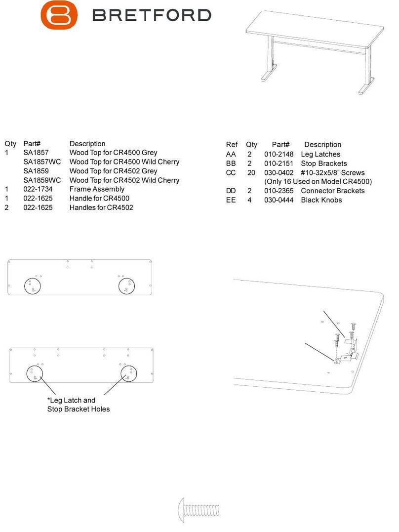
Bretford CR4500 User manual

Bretford

Bretford CR4500 User manual

Bretford EXPLORE User manual

Bretford

Bretford EXPLORE User manual

Bretford 1-Bay User manual

Bretford

Bretford 1-Bay User manual

Bretford EDU 2.0 User manual

Bretford

Bretford EDU 2.0 User manual

Bretford ec7000 User manual

Bretford

Bretford ec7000 User manual

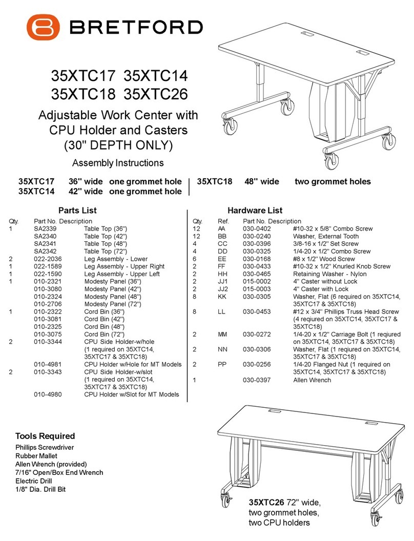
Bretford 35XTC17 User manual

Bretford

Bretford 35XTC17 User manual

Bretford 35SD27 User manual

Bretford

Bretford 35SD27 User manual

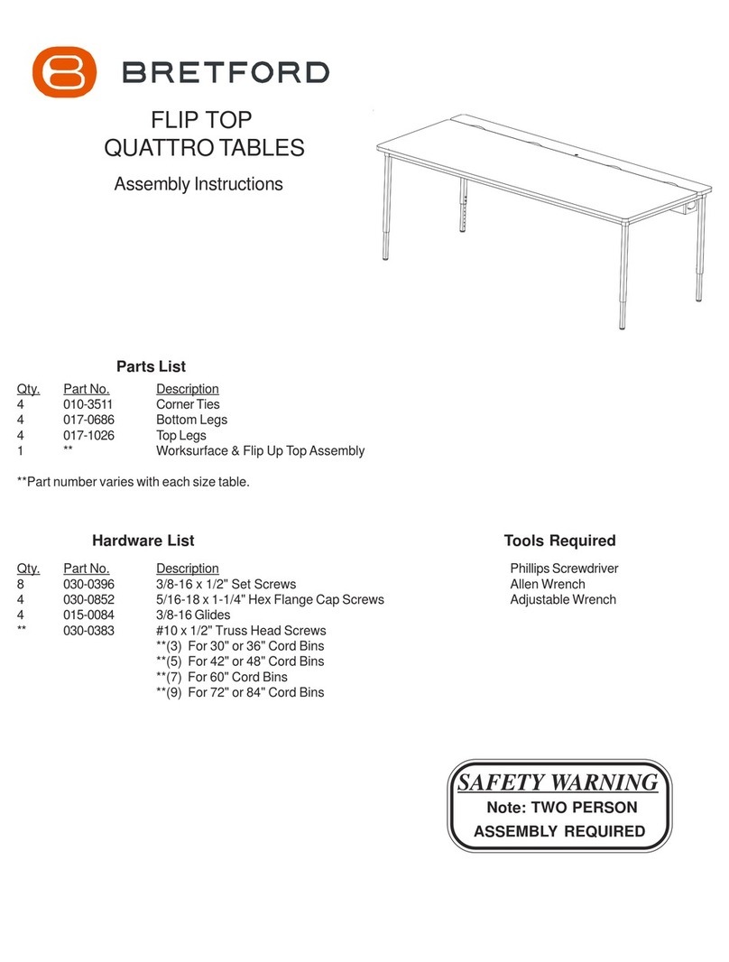
Bretford FLIP TOP QUATTRO TABLE User manual

Bretford

Bretford FLIP TOP QUATTRO TABLE User manual

Bretford TechGuard Connect User manual
Bretford

Bretford TechGuard Connect User manual

Bretford FPPC72V200 User manual

Bretford

Bretford FPPC72V200 User manual

Bretford TVSW12AC User manual

Bretford

Bretford TVSW12AC User manual
Bretford QUATTRO Computer Table User manual

Bretford

Bretford QUATTRO Computer Table User manual

Bretford TechGuard TLMTKIT5 User manual
Bretford

Bretford TechGuard TLMTKIT5 User manual

Popular Indoor Furnishing manuals by other brands

Regency LWMS3015 Assembly instructions

Regency

Regency LWMS3015 Assembly instructions

Furniture of America CM7751C Assembly instructions

Furniture of America

Furniture of America CM7751C Assembly instructions

Safavieh Furniture Estella CNS5731 manual

Safavieh Furniture

Safavieh Furniture Estella CNS5731 manual

PLACES OF STYLE Ovalfuss Assembly instruction

PLACES OF STYLE

PLACES OF STYLE Ovalfuss Assembly instruction

Trasman 1138 Bo1 Assembly manual

Trasman

Trasman 1138 Bo1 Assembly manual

Costway JV10856 manual

Costway

Costway JV10856 manual

moss DESIGN Caisson Credenza Assembly instructions

moss DESIGN

moss DESIGN Caisson Credenza Assembly instructions

Aquaglide FULL DECK 15.0 owner's manual

Aquaglide

Aquaglide FULL DECK 15.0 owner's manual

AREBOS AR-HE-SW30 user manual

AREBOS

AREBOS AR-HE-SW30 user manual

Till-Hilft Fulda 87005.330 Assembly instructions

Till-Hilft

Till-Hilft Fulda 87005.330 Assembly instructions

Twoey Outside 2010 quick start guide

Twoey Outside

Twoey Outside 2010 quick start guide

Hettich Easys 200 operating instructions

Hettich

Hettich Easys 200 operating instructions

The bedboss RELAX 404 Series owner's manual

The bedboss

The bedboss RELAX 404 Series owner's manual

Oeseder Möbelindustrie Bern 991 720 Assembly instructions

Oeseder Möbelindustrie

Oeseder Möbelindustrie Bern 991 720 Assembly instructions

Costway HW68469 user manual

Costway

Costway HW68469 user manual

Next ALIX A27743 Assembly instructions

Next

Next ALIX A27743 Assembly instructions

BROSA Hans Assembly guide

BROSA

BROSA Hans Assembly guide

Prodigg MINIKA PBA015T-FUR installation manual

Prodigg

Prodigg MINIKA PBA015T-FUR installation manual

manuals.online logo
manuals.online logoBrands
  • About & Mission
  • Contact us
  • Privacy Policy
  • Terms and Conditions

Copyright 2025 Manuals.Online. All Rights Reserved.

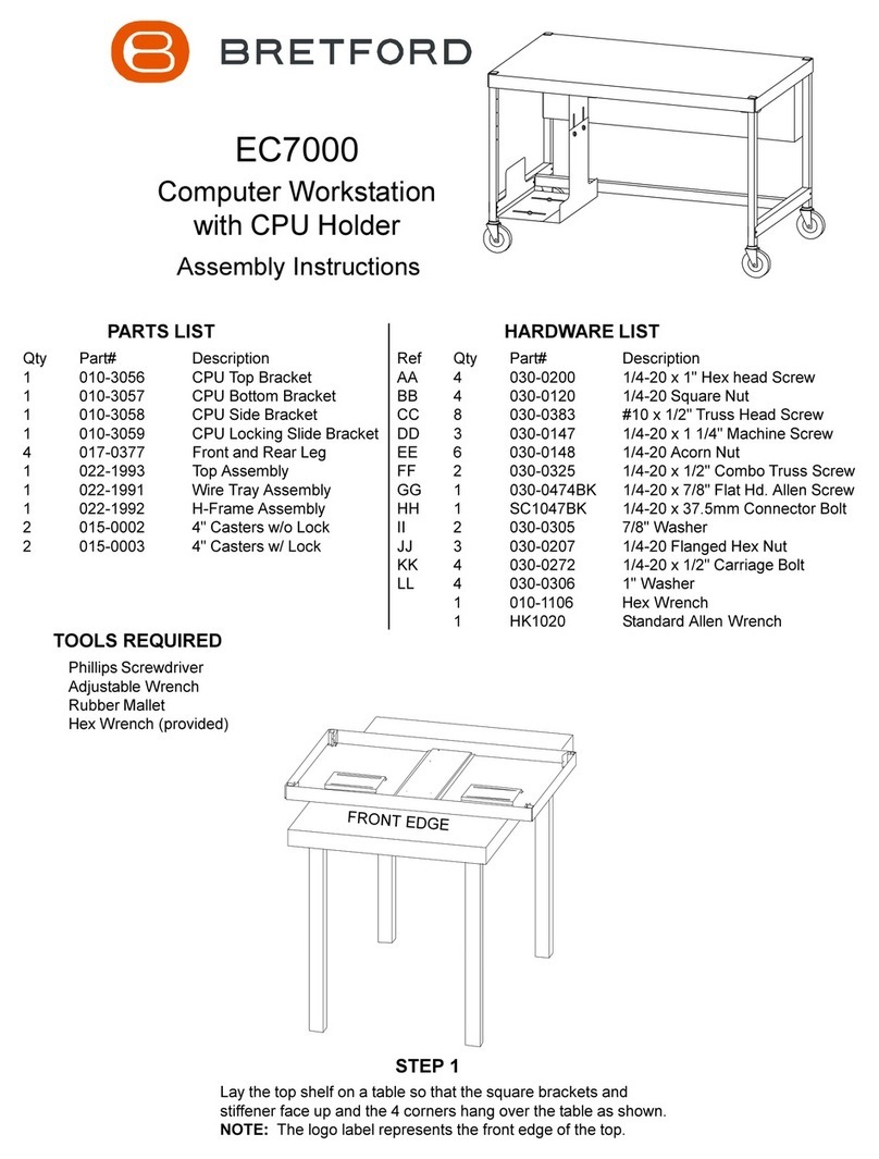
EC7000
Computer Workstation
with CPU Holder
Assembly Instructions
PARTS LIST HARDWARE LIST
Qty Part# Description
1 010-3056 CPU Top Bracket
1 010-3057 CPU Bottom Bracket
1 010-3058 CPU Si e Bracket
1 010-3059 CPU Locking Sli e Bracket
4 017-0377 Front an Rear Leg
1 022-1993 Top Assembly
1 022-1991 Wire Tray Assembly
1 022-1992 H-Frame Assembly
2 015-0002 4" Casters w/o Lock
2 015-0003 4" Casters w/ Lock
Ref Qty Part# Description
AA 4 030-0200 1/4-20 x 1" Hex hea Screw
BB 4 030-0120 1/4-20 Square Nut
CC 8 030-0383 #10 x 1/2" Truss Hea Screw
DD 3 030-0147 1/4-20 x 1 1/4" Machine Screw
EE 6 030-0148 1/4-20 Acorn Nut
FF 2 030-0325 1/4-20 x 1/2" Combo Truss Screw
GG 1 030-0474BK 1/4-20 x 7/8" Flat H . Allen Screw
HH 1 SC1047BK 1/4-20 x 37.5mm Connector Bolt
II 2 030-0305 7/8" Washer
JJ 3 030-0207 1/4-20 Flange Hex Nut
KK 4 030-0272 1/4-20 x 1/2" Carriage Bolt
LL 4 030-0306 1" Washer
1 010-1106 Hex Wrench
1 HK1020 Stan ar Allen Wrench
TOOLS REQUIRED
Phillips Screw river
A justable Wrench
Rubber Mallet
Hex Wrench (provi e )
STEP 1
Lay the top shelf on a table so that the square brackets an
stiffener face up an the 4 corners hang over the table as shown.
NOTE: The logo label represents the front e ge of the top.
FRONT EDGE
All manuals and user guides at all-guides.com
all-guides.com
EE
Sli e the H-frame between the legs as shown. The
shorter side faces the rear. Secure the frame to the legs
using screws (DD) an nuts (EE) as shown. NOTE: One
leg on the front si e DOES NOT GET HARDWARE, this is
left open for the CPU hol er. You eci e whether to leave
the right or left si e open.
DD
STEP 4
SHORTER SIDE
STEP 5
Insert each caster into the legs. If casters o not insert
easily, use a rubber mallet to tap each caster in place.
Make sure casters are SECURELY seate into the legs
before stan unit upright.
LEAVE OPEN FOR
CPU HOLDER (It can
be the right or left side
STEP 2 STEP 3
Position one leg into the square bracket so that the
cappe en is flush with the top of the shelf an the
holes face in as shown. LOOSELY attach with screws
(AA) an nuts (BB). Attach the remaining 3 legs in the
same manner.
BB
AA
Insert a self tapping screw (CC) approximately 3/4 of the
way into the first hole in each leg. Sli e each leg own so
that the square bracket rests on the shaft of the self
tapping screw, not the hea of the screw. T GHTEN ALL
SHELF HARDWARE.
CC
All manuals and user guides at all-guides.com
STEP 6
STEP 7
Sli e the locking bracket into the a justable bracket on the top shelf as shown. Align the
top bracket with both the a justable an locking bracket. Secure in place with screws
(FF). To a just top bracket, just loosen screws sli e bracket forwar or back war an
then tighten screws in place. NOTE: The locking an top bracket can be mounte to
either the right or left si e of the top shelf.
FF
TOP BRACKET
ADJUSTABLE BRACKET
BACK SIDE OF THE UNIT
Stan unit upright an position the wire tray between
the rear legs. Starting at the top, secure in place
using screws (CC) as shown.
LOCKING
BRACKET
All manuals and user guides at all-guides.com
Part #031-3240
Rev. 08.17.99 BW
Attach the si e bracket to the H-frame with screw (GG),
screws (HH), washers (II), nut (EE) an nut (JJ) as shown.
HH I I EE JJ
LL
KK
Attach the bottom bracket to the si e an top brackets with bolts (KK), washers (LL) an nuts (EE) an (JJ)
as shown. NOTE: To make any a justments to the height or wi th of the top or bottom brackets, just
loosen har ware, sli e bracket in esire irection an the retighten har ware in place.
SCREW (HH)
SCREW (GG)
NUT
(EE)
NUT
(JJ)
STEP 8
STEP 9
GG
EE JJ
LL EE
KK
JJ
Bretford Bretford Ltd.
11000 Seymour Avenue Technology House
Franklin Park, IL 60131 7 Lake nd Court, Taplow
T L: 847.678.2545 Bucks SL6 0JQ ngland
800.521.9614 T L: 01628 603558
FAX: 847.678.0852 FAX: 01628 604923
800.343.1779
www.bretford.com
All manuals and user guides at all-guides.com