manuals.online logo
Brands
  1. Home
  2. •
  3. Brands
  4. •
  5. Bticino
  6. •
  7. Intercom System
  8. •
  9. Bticino Video-Kit 2 368911 User manual

Bticino Video-Kit 2 368911 User manual

Istruzioni d’uso
Gebrauchanweisungen
Notice d’emploi
Instructions for use
Instrucciones de uso
Gebruiksaanwijzing
Istruçoes para o uso
Odhgìez Xrçshz
Bycnherwbb gj rcgkefnfwbb
Kullanım bilgileri
Instrukcja
Video - Kit
368911
PART. U3191A - 09/08-01 PC
3
w
35
185
106
o
o
o
o
45
4
Video - Kit
6
5÷10mm
3
1
24
5
7
8
5
- La telecamera non deve essere installata di fronte a grandi sorgenti luminose, oppure in luoghi dove il
soggetto ripreso rimanga molto in controluce. Per risolvere i problemi precedentemente descritti si
consiglia di variare l'altezza di installazione della telecamera, solitamente 160-165 cm, ad un’altezza di
180 cm e di orientare l’obiettivo verso il basso in modo da migliorare la qualità delle riprese.
- Nota: Le telecamere con sensore CMOS a colori presentano, in condizioni di scarsa luminosità, una
sensibilità inferiore rispetto alle telecamere in bianco/nero. Si consiglia pertanto, in ambienti poco
illuminati di prevedere una fonte di illuminazione aggiuntiva.
- Die Kamera darf nicht vor starken Lichtquellen oder an Orten installiert werden, wo das Subjekt sich
im Gegenlicht befindet. Um die zuvor erwähnten Probleme zu lösen, empfehlen wir die
Installationshöhe der Kamera zu ändern, d.h. sie anstatt auf 160-165 cm Höhe, auf 180 cm Höhe zu
installieren und das Objektiv nach unten zu orientieren, um die Aufnahmequalität zu verbessern.
- Bemerkung: Farbkameras mit CMOS-Aufnahmeelement besitzen bei schlechter Beleuchtung eine
geringere Empfindlichkeit als Schwarz/Weiß Kameras. Wir empfehlen daher eine zusätzliche
Beleuchtungsquelle vorzusehen.
- La télécaméra ne doit pas être installée en face de fortes sources lumineuses, ou bien dans des
endroits où le sujet pris reste très à contre-jour. Pour résoudre les problèmes précédemment décrits,
il est conseillé de porter la hauteur d'installation de la télécaméra, normalement 160-165 cm, à une
hauteur de 180 cm et d'orienter l'objectif vers le bas de façon à améliorer la qualité des prises de vue.
- Nota: les télécaméras avec capteur CMOS couleurs présentent, dans des conditions de faible luminosité,
une sensibilité inférieure aux télécaméras noir/blanc. Il est donc conseillé, dans des milieux peu
éclairés, de prévoir une source de lumière supplémentaire.
improve the quality of the views.
- The camera must not be installed in front of large light sources, or in places where the subject viewed
remains in deep shadow. To solve the problems described above change the height at which the
camera is installed, normally 160 to 165 cm, to a height of 180 cm, and face the lens downwards to
- Note: in poor lighting conditions cameras with colour CMOS detector are less sensitive than black/white
cameras. An extra lighting source should be added in poorly lit rooms.
- La telecámara no debe ser instalada delante de fuentes luminosas grande en lugares en donde el
individuo filmado se encuentre demasiado en contraluz. Para solucionar los problemas descritos
antes, es aconsejable modificar la altura de instalación de la telecamera, de 160-165 cm a 180 cm y
enfocar el objetivo hacia abajo para optimizar la calidad de la filmación.
- Nota: las telecámaras con sensor CMOS en colores presentan, en condiciones de escasa luminosidad,
una sensibilidad inferior respecto a las telecámaras en blanco/negro. Por lo tanto es aconsejable en
ambientes escasamente iluminados prever una fuente de iluminación extra.
- Installeer de camera niet tegenover grote lichtbronnen of op plaatsen waar de opname van het
onderwerp door sterk tegenlicht wordt gestoord. Voorgaande problemen zijn op te lossen door de
camera op een hoogte van 180 cm te installeren (in plaats van 160-165 cm) en het objectief omlaag te
richten zodat de kwaliteit van de opnames beter zal zijn.
- Opmerking: camera's met kleuren-CMOS-sensor zijn bij een zwakke verlichting minder gevoelig dan
zwart-wit camera's. Daarom is het raadzaam om zwak verlichte omgevingen van extra verlichting te
voorzien.
- A câmara não deve ser montada diante de fortes fontes de luz, ou então em lugares onde o elemento
que deve ser filmado fique muito em contraluz. Para resolver os problemas supramencionados
recomenda-se variar a altura da instalação da câmara, que habitualmente é de 160-165 cm, para uma
altura de 180 cm e orientar a objectiva para baixo a fim de melhorar a qualidade das filmagens.
- Nota: as câmaras com sensor CMOS em cores apresentam, quando há pouca luminosidade, uma
sensibilidade inferior em relação às câmaras em branco e preto. Portanto, recomenda-se, quando os
ambientes forem pouco iluminados providenciar uma fonte de iluminação adicional.
-Hkàmera den prépei na egkatastaueì mprostà se megàlez fvteinéz phgéz, çse shmeìa òpoy hlçch tvn
antikeìmenvn paraménei polù kòntra sto fvz. Gia thn epìlysh tvn problhmàtvn poy perigràfhkan
prohgoyménvz synistàtai na metabàllete to ùcoz egkatàstashz thz kàmeraz, synçuvz 160-165 ek, se
éna ùcoz 180 ek. kai na kateyuùnete to fakò proz ta kàtv étsi èste na beltiènetai hpoiòthta thz lçchz.
-Shmeìvsh: Oi kàmerez me égxrvmo aisuhtçra CMOS paroysiàwoyn, se synuçkez ellipoùz fvteinòthtaz,
mia pio xamhlç eyaisuhsìa se sxésh me tiz aspròmayrez kàmerez. Katà synépeia synistàtai, se lìgo
fvtisménoyz xèroyz na problécete mia pròsueth phgç fvtismoù.
IT
DE
FR
UK
ES
NL
PT
EL
6
Video - Kit
- Ytkmpz ecnfyfdkbdfnm ntktrfvthe yfghjnbd cbkmys[ bcnjxybrjd cdtnf6 bkb ;t - d vtcnf[6 ult cybvftvsq
j,]trn pyfxbntkmyjt dhtvz ,eltn yf[jlbnmcz ghjnbd cdtnf7 Lkz htitybz dsiterfpfyys[ ghj,ktv
cjdtnetv gjlyznm ntktrfvthe lj ecnfyjdjxyjq dscjns !*) cv6 gj chfdytyb. chtrjvtyletvjq
byfghfdbnm j,]trnbd dybp nfr6 xnj,s ekexibnm rfxtcndj c]tvrb7
- Ghbvtxfybt5 Wdtnyst ntktrfvths c xedcndbntkmysv lfnxbrjv CMOS d eckjdbz[ ckf,jq jcdtotyyjcnb
lf.n vtymie. xedcndbntkmyjcnm6 gj chfdytyb. cxthyj-,tksvb ntktrfvthfvb7 Gj'njve6 d
ckf,j-jcdtotyys[ vtcnf[ htrjvtyletncz j,tcgtxbnm ecnfyjdre ljgjkybntkmyjuj bcnjxybrf cdtnf7
,BNFSBCZLÔ¿ÔLLBZOBLMBSÔLBS¿ÔTÔOBWFZBmFLJMFOz[OFOJOB¿ÔSÔ¿FLJMEFHzMHFEFLBMEÔ»ÔZFSMFSFLVSVMNBNBMÔEÔS
%BIBzODFUBSJGFEJMNJ¿QSPCMFNMFSJmz[NMFNFLJmJOHFOFMEFDNPMBOLBNFSBLVSNBZLTFLMJ»JOJO
DNZLTFLMJ»FEF»J¿UJSJMNFTJWFNFSDF»JOmFLJNLBMJUFTJOJJZJMF¿UJSFDFL¿FLJMEFB¿B»ÔZBEP»SVZzOMFOEJSJMNFTJ
UBWTJZFFEJMJS
/PU3FOLMJCMOSEFUFLUzSMLBNFSBMBSZFUFSTJ[BZEÔOMÔL¿BSUMBSÔOEBTJZBICFZB[LBNFSBMBSBHzSFEBIBBMmBL
IBTTBTJZFUHzTUFSJSMFS#VOFEFOJMFB[BZEÔOMBOEÔSÔMBONFLBOMBSEBJMBWFCJSBZEÔOMBUNBLBZOB»ÔOÔOzOHzSMNFTJ
UBWTJZFFEJMJS
RU
TR
PL
CMOS
- Kamera nie może być instalowana naprzeciwko silnych źródeł światła lub w miejscach, gdzie obserwowany obiekt
pozostaje w głębokim cieniu (lub “pod światło”). Aby temu zapobiec, można zmienić wysokość zainstalowania
kamery (na przykład 180 cm zamiast zalecanych 160-165 cm) i skierować obiektyw w dół, aby uzyskać lepszą jakość
obrazu.
- Uwaga: w warunkach słabego oświetlenia kolorowe kamery CMOS są mniej czułe niż kamery czarno-białe. W
miejscach i pomieszczeniach słabo oświetlonych zalecane jest zamontowanie dodatkowego oświetlenia.
7
1
2
30 mm
168 mm
150 mm
160 ÷ 165 cm
IT Altezza consigliata salvo diversa normativa vigente.
DE Empfohlene Höhe falls die gesetzlichen Vorschriften
nichts anderes vorschreiben.
FR Hauteur conseillée sauf autre norme en vigueur.
UK Recommended height, unless different regulations
are specified.
ES Altura recomendada salvo normativa vigente diferente.
NL Aanbevolen hoogte behoudens andere normen in
voege.
PT Altura aconselhada a não ser se a norma em vigor
for diferente.
EL Συνιστούμενο ύψος πλην διαφορετικής ισχύουσας
νομοθεσίας
RU Рекомендуемая высота, если нет других норма-
тивных предписаний.
TR Yürürlükteki kanunlarca farklı şekilde belirlenenler
hariç olarak, tavsiye edilen yükseklik
PL Zalecana wysokość z zastrzeżeniem innych
obowiązujących przepisów
.
8
Video - Kit
1 2
4
5
6
789
10
11
3
12
IT Display
DE Display
FR Moniteur
UK Display
ES Pantalla
NL Display
PT Ecrã
EL Οθόνη
RU Дисплей
TR Ekran
PL Wyświetlacz
1 - IT Microfono
DE Mikrofon
FR Micro
UK Microphone
ES Micrófono
NL Microfoon
PT Microfone
EL Μικρόφωνο
RU Микрофон
TR Mikrofon
PL Mikrofon
2 - IT Accensione posto esterno/ciclamento
DE Einschalten einer Türstation/Taktierung
FR Allumage poste externe/cyclage
UK Switching on entrance panel/cycling
ES Encendido de la placa exterior/visualización
cíclica de telecámaras
NL Inschakeling extern punt/cyclusopvolging
PT Ligação unidade externa/mudança cíclica
EL Άναμμα εξωτερικής θέσης/έναρξης κύκλου
RU Включение наружной точки / циклирование
TR Dış ünite/periyodik işletme çalıştırılması
PL Włączenie miejsca zewnętrznego/ przewijania
3 -
/
9
IT Volume (altoparlante)
DE Lautstärke (Lautsprecher)
FR Volume (haut-parleur)
UK Volume (Loudspeaker)
ES Volumen (Altavoz)
NL Volume (Luidspreker)
PT Volume (Altifalante)
EL Ένταση (ηχείου)
RU Звук (громкоговорители)
TR Ses yüksekliği (hoparlör)
PL Natężenie dźwięku (głośnik)
5 -
IT Accensione luci scale
DE Treppenlicht einschalten
FR Allumage lumière escaliers
UK Switching on staircase lights
ES Encendido de la luz de la escalera
NL Inschakeling lichten trapzaal
PT Ligação das luzes escadas
EL Άναμμα φώτων σκάλας
RU Включение света на лестницах
TR Merdiven ışıklarının yakılması
PL Włączenie światła na klatce schodowej
4 - IT Tasto di connessione + Led
DE Schalttaste + Led
FR Touche de connexion + Led
UK Connection key + Led
ES Tecla de conexión + Led
NL Toets aansluiting + Led
PT Tecla de conexão + Led
EL Πλήκτρο σύνδεσης + Led
RU
Кнопка подключения + Светодиод
TR Bağlantı tuşu + Led
PL Klawisz łączący + Led
6 -
IT Regolazione luminosità
DE Helligkeitseinstellung
FR Réglage luminosité
UK Brightness control
ES Ajuste de la luminosidad
NL Regeling lichtsterkte
PT Regulação da luminosidade
EL Rùumish fvteinòthtaz
RU htuekbhjdrf zhrjcnb
TR Parlaklık ayarı
PL Regulacja jasności
7 - IT Altoparlante
DE Lautsprecher
FR Haut-parleur
UK Loudspeaker
ES Altavoz
NL Luidspreker
PT Altifalante
EL Ηχείο
RU Громкоговоритель
TR Hoparlör
PL Głośnik
8 - IT Regolazione colore
DE Farbeneinstellung
FR Réglage couleur
UK Colour setting
ES Ajuste del color
NL Kleurregeling
PT Regulação da cor
EL ρύθμιση χρώματος
RU Регулировка цвета
TR Renk ayarı
PL Regulacja koloru
9 -
IT
Regolazione suoneria ed esclusione
DE Ruflautstärkeregrlung und
Rufabschaltung
FR Réglage sonnerie et exclusion
UK Bell adjustment and exclusion
ES Ajuste timbre y deshabilitación
NL Afstelling en uitschakeling bel
PT Regulação campainha e exclusão
EL
rùumish koydoynioù kai ejaìreshz
RU
htuekbhjdfybt pdjyrf b jnrk.xtybt
TR
Alarm ayarlama ve hariç bırakma
PL
Regulacja głośności sygnału / wyłączenie
11 - IT
DE
FR
UK
ES
NL
PT
EL
RU
TR
PL
Pulsanti programmabili
Programmierbare Tasten
Touches programmables
Programmable pushbuttons
Pulsadores programables
Programmeerbare drukknoppen
Botões programáveis
programmatiwòmena koympià
ghjuhfvvbhetvst ryjgrb
programlanabilir butonlar
przyciski programowalne
12 -
IT Tasto serratura + Led
DE Schlosstaste + Led
FR Touche serrure + Led
UK Door lock key + Led
ES Tecla cerradura + Led
NL Toets slot + Led
PT Tecla da fechadura + Led
EL Πλήκτρο κλειδαριάς + Led
RU Кнопка замка + Светодиод
TR Kilit tuşu + Led
PL Klawisz zamka+ Led
10 -
)(
+
+
10
Video - Kit
ON
OFF
J1 J2
BUS
1
2
5
1
PM
N
ART.344182
2
3
45
6
7
1
IT Spostare su ON solo nell’ultimo videocitofono della tratta di ogni appartamento e di ogni montante.
DE Bei der letzten V ideo-Hausstation ist der Schalter auf ON zu stellen.
FR Déplacer sur ON (MARCHE) seulement dans le dernier vidéophone du parcours de chaque appartement ou de
chaque colonne montante.
UK Move to ON only in the last video internal unit of the stretch of each apartment or each riser.
ES Mueva a ON sólo el último vídeointerfono de la trama de cada departamento o de cada montante.
NL Zet slechts de laatste (beeld)huistelefoon van iedere appartementlijn verdiepingslijn op ON.
PT Desloque sobre ON somente no último intercomunicador vídeo do trecho de cada apartamento ou de
cada montante.
EL Metakinçste sto ON mòno sto teleytaìo uyrothléfvno me ouònh ç xvrìz toy méroyz kàue
diamerìsmatoz ç kàue diaklàdvshz.
RU gthtdtcnb yf ON DRK njkmrj yf gjcktlytv dbltjljvjajyt wtgb rf;ljq rdfhnbhs b
rf;ljq cnjqrb
TR Her daire ve her taflıma kolonu hattının sadece son dahili ünitesini ON üzerine getirin.
PL Ustawić w pozycji ON tylko w ostatnim wideodomofonie w obrębie pionu lub linii w mieszkaniu.
1 -
11
IT Sede dei configuratori
DE Sitz der Konfiguratoren
FR Logement configurateurs
UK Configurator seat
ES Alojamiento configuradores
NL Alojamento configurador
PT Plaats van de configuratiemodules
EL uésh prosarmostèn
RU Uytplj lkz rjyabuehfnjhjd
TR Konfiguratörler yuvası
PL gniazdo konguratorów
2 - IT J2: Master/Slave, estrarre per slave
DE
J2: Master/Slave, für Slave herausziehen
FR J2: Master/Slave, extraire pour salve
UK J2: Master/Slave, extract for slave
ES J2: Master/Slave, extraiga para slave
NL
J2: Master/Slave, uittrekken voor slave
PT J2: Master/Slave, extrair para slave
EL J2: Master/Slave, εξάγετε για slave
RU J2: Основной/ Подчиненный режим
(Master/Slave), для Подчиненного – извлечь.
TR J2: Master/Slave, slave için çıkarın
PL J2: Master/Slave, wyciągnąć dla Slave’u
3 -
IT Morsetti di collegamento per funzioni aggiuntive
DE Anschlussklemmen für zusätzliche Funktionen
FR Bornes de branchement pour fonctions
supplémentaires
UK Connection terminals for additional functions
ES Bornes de conexión para funciones adicionales
NL Klemmen van verbinding voor bijkomende
functies
PT Bornes de conexão para funções adicionais
EL Ακροδέκτες σύνδεσης για πρόσθετες λειτουργίες
RU Соединительные выводы для дополнительных функций
TR İlave işlevler için bağlantı terminalleri
PL Zacisk łączący funkcji dodatkowych
6 -
IT Morsetto per alimentazione supplementare
DE Klemme für zusätzliche Stromversorgung
FR Borne d’alimentation supplémentaire
UK Terminal for additional power supply
ES Borne para alimentación adicional
NL Klem voor supplementaire voeding
PT Borne para alimentação suplementar
EL Ακροδέκτης για συμπληρωματική τροφοδότηση
RU Вывод для дополнительного питания
TR Yedek besleme için terminal
PL Zacisk zasilania dodatkowego
5 -
IT Morsetto per collegamento al BUS
DE Klemme für den BUS-Anschluss
FR Borne de branchement au BUS
UK BUS connection terminal
ES Borne de conexión al BUS
NL Klem voor de verbinding met de BUS
PT Borne para conexão com o BUS
EL Ακροδέκτης για σύνδεση σε BUS
RU Вывод для подключения к шине (BUS)
TR BUS bağlantısı için terminal
7 -
IT J1: Jumper da rimuovere in caso di alimentatore
supplementare
DE J1: Falls eines zusätzlischen Netzgeräts muß der
Jumper entfernt werden
FR J1:
Cavalier à retirer en cas d’alimentation supplémentaire
UK J1: Jumper to be removed when there is an extra
power supply
ES J1:
Puente extraíble en caso de alimentador adicional
NL J1: Te verwijderen jumper bij het gebruik van een
extra voeding
PT J1: Jumper a ser removido se houver alimentador
suplementar
EL J1: poy afaireìtai se perìptvsh
symplhrvmatikoù trofodotikoù
RU J1: Vjcn - elfkbnm d ckexft gjlrk.xtybz
ljgjkybntkmyjuj ,kjrf gbnfybz
TR J1: Yedek besleyici durumunda sökülecek Jumper
PL J1: Usunąć zworkę, jeżeli jest dodatkowy zasilacz
4 -
JUMPER :J1
J2:/
PL Zacisk połączenia do BUS
BUS
12
Video - Kit
DYBVFYBT5 Ghb ecnfyjdrt dbltjljvjajyf
cj,k.lfnm cktle.obt ghfdbkf5
-ecnfyfdkbdfnm njkmrj dj dyenhtyyb[ gjvtotybz[
-ljk;ty ,snm pfoboty jn gjgflfybz rfgtkm bkb
,hspu djls
-yt pfrhsdfnm dtynbkzwbjyyst jndthcnbz
-ghbvtyznm njkmrj lkz lde[ghjdjlys[ cbcntv
SCS Bticino.
Bcgjkmpjdfybt ghb,jhf yt gj yfpyfxtyb. vj;tn
ytufnbdyj jnhfpbnmcz yf tuj [fhfrnthbcnbrf[
,tpjgfcyjcnb
%JLLBUEBIJMJOJUFB¿B»ÔEBLJNPOUBKLVSBMMBSÔOBVZNBMÔEÔS
TBEFDFLBQBMÔPSUBNMBSBLVSVMNBMÔEÔS
EBNMBNBZBWFZBTVQTLSUNFMFSJOFNBSV[
CÔSBLÔMNBNBMÔEÔS
IBWBMBOEÔSNBEFMJLMFSJOJLBQBUNBZÔO
TBEFDFLBCMPMV4$4#5JDJOPTJTUFNMFSJOEF
LVMMBOÔMNBMÔEÔS
fSOOIFSGBSLMÔLVMMBOÔNÔFNOJZFUz[FMMJLMFSJOJUFIMJLFZF
BUBCJMJS
Attenzione: il videocitofono deve rispettare le seguenti
regole installative:
- deve essere installato solo in ambienti interni
- non deve essere esposto a stillicidio o a spruzzi d’acqua
- non ostruire le aperture di ventilazione
- deve essere usato unicamente su sistemi 2 fili SCS
BTicino.
Ogni uso improprio dell’articolo puó comprometterne le
caratteristiche di sicurezza.
Attention: le vidéophone doit respecter les règles
d'installation suivantes:
- il doit être monté seulement à l'intérieur
- il ne doit pas être exposé à des suintements ou
à des éclaboussures
- ne pas boucher les ouvertures d'aération
- il doit être utilisé uniquement sur des systèmes 2
fils SCS BTicino.
Tout usage impropre de la référence peut
compromettre les caractéristiques de sécurité.
Caution: the video internal unit must respect the
following installation rules:
- it must only be installed indoors
- it must not be exposed to water drops or splashes
- do not block the ventilation openings
- it must be used only on SCS BTicino 2-wire systems
An improper use of the item can compromise its
safety features
Achtung: die Video-Hausstation muss unter
Beachtung folgender
Regeln installiert werden:
- es darf nur im Inneren installiert werden
- es darf nicht Wassertropfen oder -spritzer
ausgesetzt werden
- Belüftungsschlitze nicht verstopfen
- Es darf nur mit "2--Draht-Bus-System" der SCS
BTicino verwendet werden.
Jeder ungeeigneter Gebrauch des Geräts kann seine
Sicherheitseigenschaften beeinträchtigen.
Atención: el videointerfono debe respetar las siguientes
normas de instalación:
- se debe instalar sólo al cubierto
- no debe estar expuesto a goteo o salpicones de agua
- no tape las aberturas de ventilación
- se debe utilizar exclusivamente en sistemas 2 hilos
SCS BTicino.
Cualquier uso impropio del artículo puede comprometer
sus características de seguridad.
Atenção: o intercomunicador vídeo deve respeitar as
seguintes regras para ser instalado:
- deve ser instalado somente internamente
- não deve ser exposto a estilicídio ou borrifos de água
- não deve obstruir as aberturas de ventilação
- deve ser usado somente em sistemas de 2 fios da SCS
BTicino.
Qualquer uso impróprio do artigo pode comprometer as
suas características de segurança.
Let op: Bij de installatie van de huistelefoon moet men
de volgende voorschriften in acht nemen:
- binnenshuis installeren
- niet aan waterdruppels en -stralen blootstellen
- de ventilatieopeningen niet versperren
- uitsluitend in 2-dradige SCS BTicino systemen installeren
Ieder oneigenlijk gebruik kan de veiligheid van het product
schaden.
Prosoxç: hsyskeyç endoepikoinvnìaz me bìnteo prépei
na threì
toyz akòloyuoyz kanònez egkatàstashz:
-prépei na egkatastaueì mòno se kleistò xèro
-den prépei na ektìuetai se stàjimo çpitsiliéz neroù
-mhn boylènete ta anoìgmata ejaerismoù
-prépei na xrhsimopoihueì apokleistikà se
systçmata 2kalvdìvn SCS BTicino.
Kàue akatàllhlh xrçsh toy eìdoyz mporeì na uései
se kìndyno ta xarakthristikà asfaleìaz toy.
IT
DE
FR
UK
ES
NL
PT
EL
RU
TR
PL
Uwaga: wideodomofon powinien być instalowany zgod-
nie z następującymi zasadami:
- instalacja wyłącznie w budynku
- nie może być narażony na wilgoć i zalewanie wodą
- nie zasłaniać otworów wentylacyjnych
- może byś stosowany wyłącznie w systemie
2-przewodowym Bticino
Nieprawidłowe stosowanie i użycie może
ograniczyć bezpieczeństwo produktu.
13
A=Pulsante apertura serratura
Schalter Türöffner
Poussoir d’ouverture serrure
Door lock pushbutton
Pulsador apertura cerradura
Drukknop opening
Botão para abertura do trinco
Koympì anoìgmatoz kleidariàz
Ryjgrf jnrhsnbz pfvrf
,BQÔLJMJEJBmNBE»NFTJ
S+S- = 18V - 4A impulsivi - 250mA mantenimento (307max)
S+S- = 18V - 4A impulsstrom - 250mA Haltestrom (307max)
S+S- = 18V - 4A impulsifs - 250mA entretien (307max)
S+S- = 18V - 4A impulsive - 250mA holding current (307max)
S+S- = 18V - 4A impulsivos - 250mA mantenimiento (307max)
S+S- = 18V - 4A impulsief - 250mA onderhoud (307max)
S+S- = 18V - 4A instant
âneos - 250mA continuos
(307max)
S+S- = 18V - 4A palmik
à-250mA diatçrhshz
(307max)
S+S- = !*D -$F bvgekmcyst -@%)vF gjllth;fybt(307max)
44 7"FNQ
MTJZPOMVN"NVIBGB[B
(307max)
(307max)
Schema base
Übersichtszeichnung
Schéma de base
Basic diagram
Esquema básico
Basis schema
B = Chiamata al piano
Floor call
Appel à l’étage
Etagenruf
Llamada al piso
Oproep aan verdieping
Chamada ao piso
Klçsh ston òrofo
Dspjd yf 'nf;
,BUUBBSBNB
Esquema de base
Hlektrikò sxediàgramma
<fpjdfz c[tvf
5FNFM¿FNB
IT
DE
FR
UK
ES
NL
PT
EL
RU
TR
PL
5
1
Schemat podstawowy
Dzwonek przy drzwiach
Przycisk otwarcia zamka drzwi S+S- = 18V - 4A impuls - 250 mA podtrzymanie (maks. 30Ω)
14
Video - Kit
NO
NC
C
8A cosJ= 1 24Vdc 24Vac
4A cosJ= 0.7 24Vac
3A cosJ= 0.4 24Vac
S- S+ C NC NO
346250
B = Chiamata al piano
Floor call
Appel à l’étage
Etagenruf
Llamada al piso
Oproep aan verdieping
Chamada ao piso
Klçsh ston òrofo
Dspjd yf 'nf;
,BUUBBSBNB
S+
S-
Schema con serratura a relè
IT
Schéma avec serrure à relais
FR
Diagram with relay door lock
UK
Esquema con cerradura de relé
ES
Schema met slot met relais
NL
Esquema do trinco com relè
PT
Σχέδιο με κλειδαριά με ρελέ
EL
Схема с релейным замком
RU
Röleli kilitli şema
TR
5
1
DE Schema mit Schloss und Relais
Schemat ze zamkiem na przekaźnik
PL
Dzwonek przy drzwiach
A = Pulsante apertura serratura
Schalter Türöner
Poussoir d’ouverture serrure
Door lock pushbutton
Pulsador apertura cerradura
Drukknop opening
Botão para abertura do trinco
Koympì anoìgmatoz kleidariàz
Ryjgrf jnrhsnbz pfvrf
,BQÔLJMJEJBmNBE»NFTJ
Przycisk otwarcia zamka drzwi
15
Installare e collegare gli apparecchi come indicato nello schema.
Assicurarsi che durante le operazioni di montaggio degli apparecchi
l’alimentatore non sia collegato alla rete pubblica. L’alimentatore non
deve essere esposto a stillicidio o spruzzi d’acqua.
Non ostruire le aperture di ventilazione dell’alimentatore.
Prima di alimentare l’impianto vericare l’esattezza del cablaggio
ed accertarsi che la tensione di rete sia compatibile con quella
dell’alimentatore.
Posare i cavi seguendo lo schema riportato nelle pagine precedenti
in cui è indicato il numero dei cavi da predisporre e la dislocazione
sica degli apparecchi che compongono l’impianto.
La tabella della pagina seguente indica la sezione minima dei cavi in
funzione della distanza tra posto esterno e posto interno.
Die Gerate laut Plan montieren und anschlieBen.
Bei der Montage der Gerate darf das Netzgerat nicht am Niederspan-
nungsnetz angeschlossen sein.
Das Speisegerat darf nicht Tropfwasser oder Wasserspritzer ausge-
setzt werden.
Beluftungsschlitze des Speisegerats nicht verstopfen.
Bevor die Anlage mit Strom versorgt wird, sollte kontrolliert werden,
ob die Verkabeluna richtig vorgenommen wurde. Frufen Sie bitte
die Anschlusswerte
des Netzgerates mit der Netzspannung.
Bitte beachten Sie die Nummerierung der Drahte auf beigefugtem
Schaltplan.
In der Tabelle der nachfolgenden Seite ist der Mindestschnitt der
Kabel je nach Abstand zwischen Tür- und Hausstation angegeben
Monter et brancher les appareils comme indiqué sur le schéma.
S’assurer que pendant les opérations d’installation des appareils
l’alimentation n’est pas raccordée au réseau public. L’alimentation ne
doit etre exposée ni à stillation ou à pulvérisations d’eau.
Ne pas boucher les ouvertures d’aération de l’alimentation.
Avant d’alimenter l’installation, vérier que le cablage est correct
et s’assurer que la tension du réseau est compatible avec celle de
l’alimentation.
Poser les câbles d’après le schéma qui se trouve dans les pages
précédentes, sur lequel est indiqué le nombre de cables à placer et
la localisation physique des appareils qui forment
l’installation.
Le tableau de la page suivante indique la section minimale des câbles
en fonction de la distance entre poste extérieur et poste interne.
Install and connect the devices as indicated in the diagram.
Make sure that when the devices are mounted the power supply is
not connected to the public electric power line.
The power supply must not be exposed to dripping water or splashes.
Do not block the power supply ventilation openings.
Before energizing the installation chech that cabling is correct and
make sure that line voltage is compatible with power supply voltage.
Lay cables according to diagram shown in the previous pages, which
indicates the number of cables to be arranged and the layout of
devices that make up the installation.
The table on the following page indicates the minimum section
of the wires as a function of the distance between entrance panel
and audio handset.
Instalar y conectar los aparatos como se indica en el esquema. Ase-
gurarse de que durante las operaciones de montaje de los aparatos,
el alimentador no está conectado a la red pública.
El alimentador no debe estar expuesto a goteo o salpicones de agua.
No tape las aberturas de ventilación del alimentador.
Antes de alimentar la instalación, comprobar que el cableado es
correcto y asegurarse de que la tensión de red es compatible con la
del alimentador. Colocar los cables siguiendo el esquema que se da
en las páginas anteriores en las que se ha indicado el número de los
cables que hay que predisponer y la colocación sica de los aparatos
que componen la instalación. La tabla en la página siguiente indica
la sección mínima de los cables en función de la distancia entre la
unidad exterior y la unidad interior.
Installeer en verbind de apparatuur zoals aangegeven in het
schema.
Controleer voordat u de installatie aansluit op het lichtnet of de
bekabeling goed is aangelegd en of de netspanning geschikt is
voor de voeding. De voeding mag niet worden blootgesteld aan
waterdruppels of -stralen. Niet de ventilatieopeningen van de
voeding versperren.
Vergewis u ervan dat de voeding niet op het lichtnet is aangesloten
tijdens de installatie.
Leg de kabels aan volgens het schema op de volgende bladzijden
waarin het nummer van de kabels en de plaatsing van de apparaten
is aangegeven.
De tabel van de volgende pagina geeft de minimum doorsnede
van de kabels in functie van de afstand tussen binnenplaats en
buitenplaats.
Instalar e ligar os aparelhos conforme indicado no esquema.
Assegurar-se de que durante as opera,cóes de montagem dos
aparelhos, o alimentador nao está ligado à rede pública.
O alimentador nao deve ser exposto a estililicídio ou a borrifos de
água. Não obstrua as aberturas de ventila,cáo do alimentador.
Antes de ligar a corrente na instalaçao vericar se os cabos sao
correctos e certicar-se de que a tensao de rede é compativel
com a do alimentador.
Colocar os cabos se~quindo o esquema das páginas anteriores
onde se indica o número dos cabos a preparar e a disposicao sica
dos aparelhos que formam o sistema.
A tabela da página seguinte indica a secção mínima dos cabos
em
função da distância entre a unidade exterior e a unidade interior.
Egkauistàte kai syndéete tiz syskeyéz òpvz ypodeiknùetai
sto sxédio.
Bebaivueìte òti sth diàrkeia tvn energeièn topouéthshz tvn
syskeyèn to trofodotikò den eìnai syndeméno sto dìktyo toy
reùmatoz. To trofodotikò den prépei na ektìuetai se stàjimo
ç katàbregma me nerò.
Mhn boylènete ta anoìgmata aerismoù toy trofodotikoù.
Prin trofodotçsete thn egkatàstash elégjte thn akrìbeia
thz kalvdìvshz kai bebaivueìte òti h tàsh eìnai symbatç me
aytç toy trofodotikoù. Topouetçste ta kalèdia sùmfvna me
to sxédio poy paratìuetai stiz prohgoùmenez selìdez stiz
opoìez ypodeiknùetai o ariumòz tvn kalvdìvn proz etoimasìa
kai h fysikç topouéthsh tvn syskeyèn poy apoteloùn thn
egkatàstash.
Ecnfyjdbnm b gjlrk.xbnm ghb,jhs6 rfr erfpfyj d c[tvt7
Cktlbnm pf ntv6 xnj,s dj dhtvz vjynf;f ghb,jhjd ,kjr
gbnfybz yt ,sk gjlrk.xty r ctnb ‘ktrnhjgbnfybz7 <kjr
gbnfybz ljk;ty ,snm pfoboty jn gjgflfybz rfgtkm bkb ,hspu
djls7
Yt pfrhsdfnm dtynbkzwbjyyst jndthcnbz ,kjrf gbnfybz7
Gthtl ntv6 rfr gjlfnm njr d cbcntve6 ghjdthbnm ghfdbkmyjcnm
dsgjkytyyjq ghjdjlrb6 f nfr;t tckb yfghz;tybt d ctnb
cjjndtncndetn [fhfrnthbcnbrfv ,kjrf gbnfybz7
Dsgjkybnm ghjdjlre d cjjndtncndbb cj c[tvjq6 ghbdtltyyjq
yf ghtlsleob[ cnhfybwf[6 ult erfpfyj xbckj nht,etvs[
rf,tktq b abpbxtcrjt hfpvtotybt ghb,jhjd rjvgktrne.ob[
cbcntve7 D yb;tghbdtltyys[ nf,kbwf[ erfpfys vbybvfkmyst
ctxtybz ghjdjlybrjd6 d pfdbcbvjcnb jn hfccnjzybz vt;le
dyenhtyytq b dytiytq njxrfvb7
Cihazları flemada gösterildi¤i gibi kurunuz ve ba¤layınız. Cihazların
montaj ifllemlerinin gerçeklefltirilmesi esnasında, besleyicinin genel
flebekeye ba¤lı olmadı¤ını kontrol ederek emin olunuz.
Besleyici su damlamaları veya püskürmelerine maruz kalma-
malıdır.
Besleyicinin havalandırma açıklıklarını tıkamayınız.
Tesise elektrik vermeden önce kablo ba¤lantılarının do¤rulu¤unu
kontrol ediniz ve flebeke geriliminin besleyici gerilimine uygun
oldu¤undan emin olunuz. Kabloları, hazır edilmesi gereken
kablo sayısının ve tesisi oluflturan cihazların fiziki yerleflimlerinin
gösterildi¤i, önceki sayfalarda bulunan flemaya uygun olarak
döfleyiniz. Afla ıdaki sayfadaki tablo dıfl ünite ile iç ünite arasındaki
mesafeye göre kabloların minimum kesitini gösterir.
Zainstalować i podłączyć elementy instalacji według wskazówek
podanych na schemacie. Upewnić się, że podczas instalacji zasilacz
nie jest podłączony do sieci. Zasilacz nie może być narażony na
wilgoć lub zalewanie wodą. Nie zasłaniać otworów wentylacyjnych
zasilacza. Przed podłączeniem zasilania do instalacji, upewnij się,
że podłączenia są wykonane prawidłowo, a napięcie podane z
sieci jest zgodne z napięciem pracy zasilacza. Kable powinny
być ułożone zgodnie ze schematem podanym w instrukcji,
obejmującym liczbę przewodów oraz zyczne rozmieszczenie i
połączenie elementów wchodzących w skład instalacji.
Tabela na następnej stronie zawiera dane dotyczące minimalnego
przekroju przewodów, jakie należy zastosować, w zależności od
odległości i liczby aparatów wewnętrznych.
IT PT
EL
RU
TR
PL
DE
FR
UK
ES
NL
16
Video - Kit
140m 200m
200m
200m
200m
200m
200m
130m
17
Konguration Türstation:
P = muss nicht konguriert werden
N = muss nicht konguriert werden
T = ZEITGEBER SCHLOSSRELAIS
S = muss nicht konguriert werden
Conguración placa exterior:
P = no debe estar congurado
N = no debe estar congurado
T = TEMPORIZADOR RELÉ CERRADURA
S = no debe estar congurado
Conguratie externe plaats:
P = moet niet gecongureerd worden
N = moet niet gecongureerd worden
T = TIMER DEURSLOTRELAIS
S = moet niet gecongureerd worden
Entrance panel conguration:
P = must not be congured
N = must not be congured
T = DOOR LOCK TIMER RELAY
S = must not be congured
Congurazione posto esterno:
P = non deve essere congurato
N = non deve essere congurato
T = TEMPORIZZATORE SERRATURA
S = non d
eve essere congurato
Conguration poste extérieur:
P = ne doit pas être conguré
N = ne doit pas être conguré
T = TEMPORISATEUR RELAIS SERRURE
S = ne doit pas être conguré
0= aucun
configurateur
123456 7
1 sec. 2 sec. 3sec.
comme
poussoir
6 sec. 8sec. 10 sec.
4 sec.
numéro duconfigurateur
ATTENTION: Chaque fois que l’on modie la congu-
ration, il faut retirer, puis redonner l’alimentation à
l’installation, après avoir attendu environ 1 minute.
0= kein
Konfigurator 123456 7
1 Sek. 2 Sek. 3Sek.
Wie
Taste
6 Sek. 8Sek. 10 Sek.
4 Sek.
Konfiguratornummer
ACHTUNG: Jedes Mal, wenn die Konfiguration
geändert wird, den Strom abschalten, etwa 1 Minute
warten und dann wieder einschalten.
ATTENZIONE:Tutte le volte che si modica la congu-
razione è necessario togliere e ridare l’alimentazione
all’impianto, attendendo circa 1 minuto.
0= geen
configurator 1234567
1 sec. 2 sec. 3sec.
alsde
drukknop
6 sec. 8sec. 10 sec.
4 sec.
Configurator nummer
LET OP: Na iedere wijziging in de conguratie moet de
installatie ongeveer 1 minuut van het elektriciteitsnet
worden afgesloten.
0= ningun
configurador 1234567
1 seg. 2 seg. 3seg.
come
pulsador
6 seg. 8seg. 10 seg.
4 seg.
Numero del configurador
ATENCIÓN: Cada vez que modica la conguración,
es necesario cortar y volver a dar alimentación a la
instalación, después de esperar aproximadamente
1 minuto.
CAUTION: Every time the conguration is altered
the system must be switched o and back on again,
waiting for about 1 minute.
0= nessun
configuratore
123456 7
1 sec. 2 sec. 3sec.
come
pulsante
6 sec. 8sec. 10 sec.
4 sec.
numero del configuratore
0= no
configurator 1234567
1 Sec. 2 Sec. 3Sec.
As
pushbutton
6 Sec. 8Sec. 10 Sec.
4 Sec.
Number of the configurator
IT
DE
FR
UK
ES
NL
18
Video - Kit
Dıfl ünite konfigürasyonu:
P = konfigüre edilmemelidir
N = konfigüre edilmemelidir
T= K‹L‹TLEME RÖLES‹ ZAMAN AYARLAYICISI
S = konfigüre edilmemelidir
diamòrfvsh ejvterikoù shmeìoy:
P = den prépei na diamorfvueì
N = den prépei na diamorfvueì
T
= XRONODIAKOPTHS RELE KLEIDARIAS
S = den prépei na diamorfvueì
Conguração unidade externa:
P = não deve ser congurado
N = não deve ser congurado
T = TEMPORIZADOR DO RELÉ DA FECHADURA
S = não deve ser congurado
DYBVFYBT5 gjckt k.,jq vjlbabrfwbb rj-
yabuehfwbb ytj,[jlbvj j,tcnjxbnm cbcntve
ghbvthyj yf ! vbyene7
Rjyabuehfwbz dytiytq njxrb
P = yt gjlkt;bn rjyabuehfwbb
N = yt gjlkt;bn rjyabuehfwbb
T
‚ HTKT DHTVTYB PFVRF
S = yt gjlkt;bn rjyabuehfwbb
0= kanénaz
diamorfvtçz 1234567
1
deyt
.2
deyt
.3
deyt
.
Stàmpa
plçktroy
6
deyt
.8
deyt
.10
deyt
.
4 deyt.
Ariumòz thz diamòrfvshz
PROSOXH: Kàue forà poy tropopoieìtai h
diamòrfvsh eìnai aparaìthto na kòcete kai
na epanaférete thn trofodòthsh sthn egkatà-
stash, anaménontaz perìpoy 1 leptò.
0= nenhum
configurador 1234567
1 seg. 2 seg. 3seg.
como
botão
6 seg. 8seg. 10 seg.
4 seg.
Numero do configurador
ATENÇÃO: Todas as vezes que se modicar a con-
guração é necessário ligar e desligar a instalação da
energia eléctrica, esperando cerca de 1 minuto.
D‹KKAT: Kon

gürasyonun de
¤
ifltirildi
¤
i her defa,
tesisin beslemesini kesmek ve sonra yaklaflık 1
dakika bekleyerek yeniden beslemek gereklidir.
0= ,tp
rjyabuehfnjhf 1234567
1 c7
2
c7
3
c7 Rfr
ryjgrf
6
c7
8
c7
10
c74 c7
yjvth rjyabuehfnjhf
0= konfi-
güratör yok 1234567
1
san.
2
san.
3
san. tus
gibi
6
san.
8
san.
10
san.4 san.
Konfigüratör numarası
Konguracja panelu zewnętrznego:
P = nie może być kongurowane
N = nie może być kongurowane
T = CZAS DZIAŁANIA PRZEKAŹNIKA ZAMKA
S = nie może być kongurowane
0= bez
konfiguratora 1234567
1
sek.
2
sek.
3
sek. jak
przycisk
6
sek.
8
sek.
10
sek.4 sek.
numer konfiguratora
UWAGA: Przy każdej zmianie konguracji system
musi zostać wyłączony, a po upływie 1 minuty po-
nownie podłączony do zasilania.
26
PT
EL
RU
TR
PL
19
Regolazione del volume:
Se si manifestasse il disturbo del schio, (eetto Larsen), ridurre
prima la potenza del microfono , agendo con un cacciavite sul
potenziometro corrispondente, no ad un livello accettabile. Qualora
il fenomeno persista, agire sul potenziometro dell’altoparlante
in modo da eliminare l’inconveniente. Se il volume è troppo basso,
aumentare prima il volume dell’altoparlante ed eventualmente
anche quello del microfono, tenendo presente che è preferibile una
trasmissione chiara e priva di disturbi, che una al limite dell’innesco
(Larsen).
Regulação do volume:
Se se manifestar uma interferência no som (efeito de Larsen),
começar por diminuir a potência do microfone , rodando o poten-
ciómetro correspondente com uma chave de parafusos, até obter um
nível aceitável. Se o fenómeno persistir, regular o potenciómetro do
altifalante de modo a eliminar o problema. Se o volume estiver
demasiado baixo, começar por aumentar o volume do altifalante e
depois, se necessário, o do microfone, tendo presente que é melhor
ter uma transmissão clara e sem interferências, que uma no limiar de
início de efeitos Larsen.
Einstellung der Lautstärke:
Beim etwaigen Auftreten eines Pfeiftones (Larsen-Eekt), zuerst
die Lautstärke des Mikrophones bis auf einen annehmbaren Wert
herabsetzen, indem man das entsprechende Potentiometer mit einem
Schraubendreher einstellt. Sollte die Störung weiterhin bestehen, dann
das Potentiometer des Lautsprechers
bis zur Beseitigung des Pfeiftones
einstellen. Ist die Lautstärke nun zu niedrig, dann zuerst die des Lautspre-
chers und erst danach evtl. auch die des Mikrophones erhohen, wobei
ein deutlicher und störungsfreier Empfang einem an der Störungsgrenze
liegendem (Larsen-Eekt) vorzuziehen ist.
Réglage du volume:
Lors de siement (eet de Larsen), reduire d’abord la puissance
du micro , sur le potentiomètre correspondant, à l’aide d’un tourne-
vis, jusqu’à l’obtention d’un niveau satisfaisant. Si le siement persiste,
régler le potentiomètre du hautparleur jusqu’à l’élimination de
celui-ci. Si le volume est trop bas, augmenter d’abord la puissance du
haut-parleur et éventuellement celle du micro, en considérant qu’une
réception claire et sans parasite est préférable à une communication
à la limite de l’accrochage (eet de Larsen).
Adjustment volume:
In case of a whistle (Larsen eect), rst reduce the microphones
power, adjusting the corresponding potentiometers with a screw
driver, until an acceptable level is reached. Should the whistle persist,
adjust the loudspeakers volume in order to eliminate the trouble.
If the volume is too low level then, increase rst the potentiometer of
the loudspeaker and secondly the one for the microphone, bearing in
mind that a clear and noise free reception is preferable than one just
before whistling (Larsen).
Regulación del volumen:
Si se manifesta el silbido de acoplamiento, (efecto Larsen),
reducir primero la potencia del micrófono , girando con un
destornillador el potenciómetro correspondiente, hasta obtener un
nivel aceptable. Si el fenómeno persistiera, regular el potenciómetro
del altavoz hasta eliminar la interferencia. Si el volumen es dema-
siado bajo, aumentar primero el volumen del altavoz y eventualmente
también el del micrófono, teniendo en cuenta que es preferible una
transmissión clara y limpia de interferencias, que una al limite del
acoplo (Larsen).
De geluidssterkte regelen:
Als er een uittoon hoorbaar is (eect van Larsen): verminder eerst
het vermogen van de microfoon met behulp van een schroevendraaier
zijn stroomregelaar zo te regelen dat de geluidssterkte van het geuit
aanvaardbaar is. Als het verschijnsel niet verdwijnt, dan moet u ook de
stroomregelaar van de luidspreker
bijstellen.
Als de geluidssterkte nu
te klein is, verhoog dan eerst de geluidssterkte van de luidspreker en daarna
eventueel ook die van de microfoon, en denk er bij het bijstellen aan dat
een duidelijk hoorbaar en ongestoord geluid beter is dan een harder geluid
op de grens van het Larsen eect.
Rùumish toy çxoy:
Eàn paroysiasteì h parenòxlhsh toy sfyrìgmatoz, (efé
Larsen), meièste prèta thn isxù toy mikrofènoy , drèntaz
me éna katsabìdi sto antìstoixo potensiòmetro, méxri éna
apodektò epìpedo. Eàn to pròblhma paraménei, dràte sto po-
tensiòmetro toy hxeìoy étsi èste na ejaleifteì h dysxéreia.
Eàn h éntash eìnai polù xamhlç, ayjçste prèta thn éntash
toy hxeìoy ki endexoménvz kai toy mikrofènoy, lambànontaz
ypòch òti eìnai protimòterh mia kauarç kai xvrìz paràsita
metàdosh, apò mìa sta òria toy kacìmatoz (Larsen).
Htuekbhjdfybt pderf5
D ckexft gjzdktybz cdbcnf | aatrn Kfhctyf\ cyfxfkf
cybpbnm ehjdtym pderf vbrhjajyf , jnhtuekbhjdfd jn-
dthnrjq cjjndtncnde.obq gjntywbjvtnh lj ye;yjuj ehjdyz7
Tckb ltatrn yt bcxtpytn6 njulf jnhtuekbheqnt gjntywbjvtnh
pderjdjq rjkjyrb
lj gjkyjuj bcxtpyjdtybz cdbcnf7 Lkz
edtkbxtybz ehjdyz pderf cyfxfkf gjdscbnm ehjdtym pderf
pderjdjq rjkjyrb6 f gjnjv6 tckb gjnht,etncz6 nj b vbrhjajy6
exbnsdfz ghb njv6 xnj xbcnfz gthtlfxf ,tp gjvt[ ghtlgjxnbn-
tkmytt rfxtcnde pderf yf ghtltkmyjv ehjdyt |Kfhcty\7
Ses ayarı:
Çınlama paraziti ile karflılaflılması halinde (Larsen etkisi),
iliflkin potansiyometre üzerinde bir tornavida ile hareket ederek,
kabul edilebilir bir seviyeye kadar önce mikrofonun gücünü
azaltınız. Parazitin devam etmesi halinde, istenmeyen bu
durumu ortadan kaldıracak flekilde hoparlörün potansiyome-
tresi üzerinde müdahalede bulununuz. Ses çok alçak ise, önce
hoparlörün sesini ve gerekirse mikrofonun sesini de yükseltiniz.
Bunu yaparken temiz ve parazitsiz bir yayının çınlama sınırında
bir yayına tercih edildi¤ini unutmayınız (Larsen).
Regulacja poziomu głośności dźwięku (A):
W przypadku pojawienia się sprzężenia/gwizdu (efekt Larsena),
należy najpierw zmniejszyć moc mikrofonu , regulując odpowiedni
potencjometr śrubokrętem, aż do osiągnięcia wymaganego poziomu.
Jeżeli nie przyniesie to pożądanego efektu, regulować potencjometr
głośnika , aż do usunięcia sprzężenia. W razie zbyt niskiego poziomu
głośności, należy najpierw zwiększyć moc głośnika, a dopiero potem
mikrofonu, mając na uwadze, że lepszy jest przekaz niezakłócony,
niż taki, który występuje bezpośrednio przed wystąpieniem gwizdu
(Larsen).
IT
DE
FR
UK
ES
NL
PT
EL
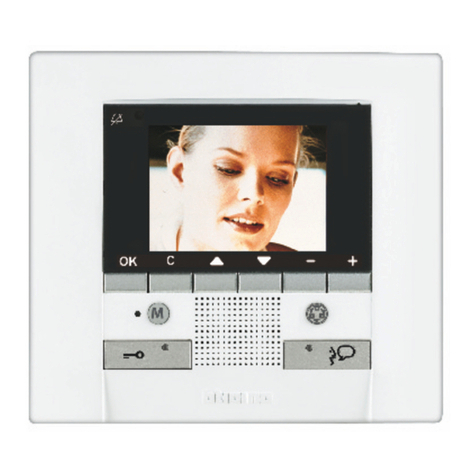
RU
TR
PL
20
Video - Kit
Selezione suoneria
La suoneria di chiamata del citofono è selezionabile tra 16
dierenti tipi di melodie. Si possono dierenziare le seguenti
tipologie di chiamata:
• Chiamata al piano
• Chiamata da posto esterno
• Chiamata intercom
Selecção toques
Os toques de chamada do intercomunicador podem ser
seleccionados em 16 tipos de melodias diferentes. Podem
ser diferenciados os seguintes tipos de chamada:
• Chamada ao piso
• Chamada da unidade externa
• Chamada Intercom
Läutwerk wählen
Für das Läutwerk der Rufe des haustelefons stehen 16
verschiedene Melodien zur Verfügung. Die Rufe können
folgendermaßen dierenziert werden:
• Etagenruf
• Ruf von der Türstation
• Intercom Anruf
Sélection sonnerie
La sonnerie d’appel du phone peut être sélectionnée parmi
16 diérents types de mélodies. On peut diérencier les
typologies d’appel suivantes:
• Appel à l’étage
• Appel de poste extérieur
• Appel intercom
Bell selection
The door entry unit call bells can be selected from 16
dierent types of tune. The following types of call can be
dierentiated:
• Call to the oor
• Call from entrance panel
• Intercom Call
Selección del timbre
El timbre del llamada del interno fono se puede seleccionar
entre 16 melodías diferentes. Es posible diferenciar las
siguientes tipologías de llamadas:
• Llamada a la planta
• llamada desde puesta exterior
• Llamada interna
Beltoon kiezen
De oproepbeltoon van de telefoon biedt de keus uit 16
melodiën. Het is mogelijk om de volgende types oproepen
te kenmerken:
• Oproep aan de verdieping
• Oproep vanuit het deurstation
• Intercom oproep
Epilogç hxhtikçz syskeyçz
To koydoùnisma klçshz thz syskeyçz endoepikoin-
vnìaz me sçma bìnteo epilégetai metajù 16 diafore-
tikèn tùpvn melvdìaz. Mporoùn na diaforopoihuoùn
oi akòloyuez typologìez klçshz:
• Klçsh ston òrofo
• Klçsh apò ejvterikò shmeìo
• Klçsh Intercom
Ds,jh pdjyrf
Djpvj;yjcnm ds,jhf jlyjq bp 16 hfpys[ vtkjlbq
lkz dspsdyjuj pdjyrf c dbltjljvjajyf7 Gj nbgfv
dspjds vjuen ,snm hfpltktys yf cktle.obt5
• Dspjd yf nf;
• Ddspjd c yfhe;yjq njxrb
• Dspjd gj bynthrjve
Alarm seçimi
Sistemi arama alarmı 16 farklı melodi tipi arasından seçi-
lebilir. Afla¤’dbıdaki arama tipleri farklılafltırılabilirler:
• Katta arama
• Dıfl üniteden ça¤rı
• ‹nterkom arama
Wybór dźwięku sygnału wywołania
Dźwięk sygnału wywołania może być wybrany spośród 16
dostępnych dźwięków. Możliwe jest przypisanie różnych
dźwięków do różnych źródeł wywołania, np.:
• Wywołanie z dzwonka przy drzwiach
• Wywołanie z panelu zewnętrznego
• Wywołanie interkomowe
IT
DE
FR
UK
ES
NL
PT
EL
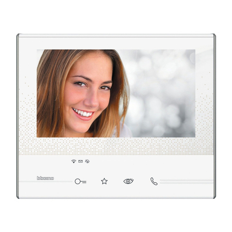
RU
TR
PL

Other Bticino Intercom System manuals

Bticino 366811 User manual

Bticino

Bticino 366811 User manual

Bticino 342982 User manual

Bticino

Bticino 342982 User manual

Bticino 322040 User manual

Bticino

Bticino 322040 User manual

Bticino 367511 User manual

Bticino

Bticino 367511 User manual

Bticino elkesan V16M User manual

Bticino

Bticino elkesan V16M User manual

Bticino Terraneo 306000 User manual

Bticino

Bticino Terraneo 306000 User manual

Bticino 322020 User manual

Bticino

Bticino 322020 User manual

Bticino 313271 User manual

Bticino

Bticino 313271 User manual

Bticino TERRANEO 312124 User manual

Bticino

Bticino TERRANEO 312124 User manual

Bticino 374004 User manual

Bticino

Bticino 374004 User manual

Bticino 2 WIRE VIDEO DOOR ENTRY AND HOME VIDEO SURVEILLANCE... User manual

Bticino

Bticino 2 WIRE VIDEO DOOR ENTRY AND HOME VIDEO SURVEILLANCE... User manual

Bticino 343100 User guide

Bticino

Bticino 343100 User guide

Bticino Terraneo 363211 User manual

Bticino

Bticino Terraneo 363211 User manual

Bticino 346310 User manual

Bticino

Bticino 346310 User manual

Bticino 344782 Operating manual

Bticino

Bticino 344782 Operating manual

Bticino 374004 User manual

Bticino

Bticino 374004 User manual

Bticino B9576C User manual

Bticino

Bticino B9576C User manual

Bticino Terraneo 332550 User manual

Bticino

Bticino Terraneo 332550 User manual

Bticino Axolute 349311 User manual

Bticino

Bticino Axolute 349311 User manual

Bticino Axolute Outdoor 349140 User manual

Bticino

Bticino Axolute Outdoor 349140 User manual

Bticino Terraneo 342620 User manual

Bticino

Bticino Terraneo 342620 User manual

Bticino 8005543561447 User manual

Bticino

Bticino 8005543561447 User manual

Bticino terraneo User manual

Bticino

Bticino terraneo User manual

Bticino LINEA 3000 User manual

Bticino

Bticino LINEA 3000 User manual

Popular Intercom System manuals by other brands

HIK VISION DS-KD8003-IME1 user manual

HIK VISION

HIK VISION DS-KD8003-IME1 user manual

HIK VISION D Series quick start guide

HIK VISION

HIK VISION D Series quick start guide

HIK VISION DS-KH6320-WTDE1 quick start guide

HIK VISION

HIK VISION DS-KH6320-WTDE1 quick start guide

Planet HDP-1160PT user manual

Planet

Planet HDP-1160PT user manual

HIK VISION KH6 Series user manual

HIK VISION

HIK VISION KH6 Series user manual

Flyingvoice i86 Series user guide

Flyingvoice

Flyingvoice i86 Series user guide

V-Tec DT596/KP user manual

V-Tec

V-Tec DT596/KP user manual

V-Tec DT-DJ4 user manual

V-Tec

V-Tec DT-DJ4 user manual

ProAudio INTERCOM 200 series user manual

ProAudio

ProAudio INTERCOM 200 series user manual

V-tech IS741IS741 user manual

V-tech

V-tech IS741IS741 user manual

basIP AV-08FB user manual

basIP

basIP AV-08FB user manual

HIK VISION DS-KH6320-TDE1 Series Configuration guide

HIK VISION

HIK VISION DS-KH6320-TDE1 Series Configuration guide

Abus TVHS30000 operating instructions

Abus

Abus TVHS30000 operating instructions

Firecom 3010 Series Installation & operation manuals

Firecom

Firecom 3010 Series Installation & operation manuals

HIK VISION DS-KD8003-IME2 user manual

HIK VISION

HIK VISION DS-KD8003-IME2 user manual

Clear-Com ICS-102 instruction manual

Clear-Com

Clear-Com ICS-102 instruction manual

basIP AA-07FB user manual

basIP

basIP AA-07FB user manual

Bitron Video AV1860/30 instruction manual

Bitron Video

Bitron Video AV1860/30 instruction manual

manuals.online logo
manuals.online logoBrands
  • About & Mission
  • Contact us
  • Privacy Policy
  • Terms and Conditions

Copyright 2025 Manuals.Online. All Rights Reserved.