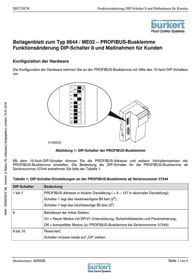
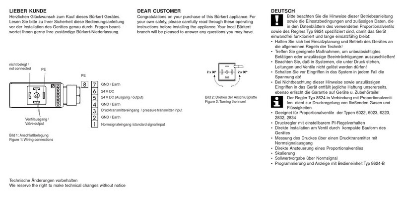
Burkert 8644 AirLINE User manual

Operating Instructions
Bedienungsanleitung
Manuel d‘utilisation
Type 8644
AirLINE
With decentralized peripheral system ET200S (Siemens)

We reserve the right to make technical changes without notice.
Technische Änderungen vorbehalten.
Sous réserve de modifications techniques.
© Bürkert Werke GmbH & Co. KG, 2002 - 2018
Operating Instructions 1805/10_EU-EN_00804729 / Original DE

3
Table of ConTenTs
1. OPERATING INSTRUCTIONS ........................................................................................................................................................6
1.1. Symbols ......................................................................................................................................................................................6
2. AUTHORIZED USE .............................................................................................................................................................................7
2.1. Restrictions ...............................................................................................................................................................................7
2.1.1. Explosion protection approval ................................................................................................................ 7
3. BASIC SAFETY INSTRUCTIONS .................................................................................................................................................8
4. GENERAL INFORMATION ................................................................................................................................................................9
4.1. Contact Addresses ................................................................................................................................................................9
4.2. Warranty ......................................................................................................................................................................................9
4.3. Licenses ......................................................................................................................................................................................9
4.4. Information on the Internet ...............................................................................................................................................9
5. SYSTEM DESCRIPTION ................................................................................................................................................................10
5.1. Application area ...................................................................................................................................................................10
5.2. Description of the system ..............................................................................................................................................10
5.3. Structure of the system ...................................................................................................................................................11
5.4. Characteristic features and advantages.................................................................................................................12
5.4.1. Characteristic features of AirLINE .............................................................................................................12
5.4.2. Advantages of AirLINE .....................................................................................................................................12
5.5. Diagram of the valve block ............................................................................................................................................13
5.6. Exploded drawing ...............................................................................................................................................................14
5.6.1. Exploded drawing - add-on dimension 11 mm ................................................................................14
5.6.2. Exploded drawing - add-on dimension 16.5 mm ............................................................................15
6. TECHNICAL DATA .............................................................................................................................................................................16
6.1. Operating Conditions ........................................................................................................................................................16
6.2. Technical data of the entire system ..........................................................................................................................16
6.3. Technical Data of the valve block ..............................................................................................................................17
6.4. Pneumatic data of the connection modules ........................................................................................................19
Type 8644 AirLINE - Siemens
english
Type 8644

4
6.4.1. Dimensioning of the connection modules .........................................................................................19
6.4.2. Performance features from the point of view of the entire system...............................................20
6.5. Electrical Data .......................................................................................................................................................................21
6.5.1. Electronic base module ME02, ME03 / 2-fold monostable ..........................................................21
6.5.2. Electronic base module ME02, ME03 / 4-fold monostable ..........................................................22
6.5.3. Electronic base module ME02, ME03 / 2-fold bistable .................................................................23
6.5.4. Electronic base module ME02 / 2-fold 2 x monostable .................................................................24
6.5.5. Electronic base module ME03 / 3-fold 10 mm monostable .........................................................25
7. STRUCTURE AND FUNCTION OF THE MODULES ........................................................................................................26
7.1. Valve block .............................................................................................................................................................................26
7.1.1. Connection modules / feeds ................................................................................................................26
7.1.2. Valve discs MK03 ....................................................................................................................................27
7.2. Connection modules .........................................................................................................................................................29
7.2.1. Structure of the connection module ...................................................................................................29
7.2.2. Connection modules, pneumatic - on left Type ME02 ...................................................................31
7.2.3. Connection modules, pneumatic - in middle Type ME02 ..............................................................32
7.2.4. Connection modules, pneumatic - on right Type ME02.................................................................33
7.2.5. Connection modules, pneumatic - on left Type ME03 ...................................................................34
7.2.6. Connection modules, pneumatic - in middle Type ME03 ..............................................................35
7.2.7. Connection modules, pneumatic - on right Type ME03.................................................................36
7.3. Electronic base module ...................................................................................................................................................37
7.3.1. General Description ................................................................................................................................37
7.3.2. Electronic base module ME02 / 2-fold monostable .......................................................................39
7.3.3. Electronic base module ME02 / 4-fold monostable .......................................................................40
7.3.4. Electronic base module ME02 / 2-fold bistable ..............................................................................41
7.3.5. Electronic base module ME02 / 2-fold 2 x monostable .................................................................42
7.3.6. Electronic base module ME03 / 2-fold monostable .......................................................................43
7.3.7. Electronic base module ME03 / 4-fold monostable .......................................................................44
7.3.8. Electronic base module ME03 / 3-fold 10 mm monostable .........................................................45
7.3.9. Electronic base module ME03 / 2-fold bistable ..............................................................................46
7.4. Pneumatic base module .................................................................................................................................................47
7.4.1. General Description ................................................................................................................................47
7.4.2. Pneumatic base module with integrated P shut-off ........................................................................48
7.5. Valves ........................................................................................................................................................................................50
english
Type 8644

5
7.5.1. General Description ................................................................................................................................50
8. INSTALLATION ...................................................................................................................................................................................53
8.1. Safety instructions .............................................................................................................................................................53
8.2. Removing the valve block from the top-hat rail .................................................................................................54
8.3. Installing the AirLINE system (e.g. in the control cabinet) ...........................................................................56
8.4. Changing the function module ....................................................................................................................................56
8.5. Fluid Installation ..................................................................................................................................................................57
8.5.1. Pneumatic connections - feed .............................................................................................................58
8.5.2. Removing the plug-in connections......................................................................................................58
8.5.3. Pneumatic connections - valve discs .................................................................................................59
8.6. Electrical Installation .........................................................................................................................................................60
9. MAINTENANCE, TROUBLESHOOTING .................................................................................................................................61
9.1. Safety instructions .............................................................................................................................................................61
9.2. Troubleshooting ...................................................................................................................................................................61
9.3. Maintenance of components ........................................................................................................................................62
9.3.1. UL handling ...............................................................................................................................................62
10. START-UP .............................................................................................................................................................................................63
10.1. Safety instructions .............................................................................................................................................................63
10.2. Fluid start-up .........................................................................................................................................................................63
10.3. Electrical start-up ................................................................................................................................................................63
10.3.1. Selection of the modules in the GSD file ..........................................................................................64
11. PACKAGING AND TRANSPORT ...............................................................................................................................................65
12. STORAGE ..............................................................................................................................................................................................66
13. DISPOSAL ............................................................................................................................................................................................66
english
Type 8644

6
Operating Instructions
1. OPERATING INSTRUCTIONS
The operating instructions describe the entire life cycle of the device. Keep these instructions in a location which is
easily accessible to every user, and make these instructions available to every new owner of the device.
WARNING!
The operating instructions contain important safety information!
Failure to observe these instructions may result in hazardous situations.
• The operating instructions must be read and understood.
1.1. Symbols
DANGER!
Warns of an immediate danger!
• Failure to observe the warning will result in a fatal or serious injury.
WARNING!
Warns of a potentially dangerous situation!
• Failure to observe the warning may result in serious injuries or death.
CAUTION!
Warns of a possible danger!
• Failure to observe this warning may result in a moderate or minor injury.
NOTE!
Warns of damage to property!
• Failure to observe the warning may result in damage to the device or the equipment.
Indicates important additional information, tips and recommendations.
Refers to information in these operating instructions or in other documentation.
→designates a procedure which you must carry out.
english
Type 8644

7
Authorized use
2. AUTHORIZED USE
Non-authorized use of the AirLINE may be dangerous to people, nearby equipment and the
environment.
• The device is designed for use in an environment where there is a risk of explosion. Pneumatically operated
devices may be used for control.
• Do not use the device outdoors unprotected.
• Use according to the authorized data, operating conditions and conditions of use specified in the contract
documents and operating instructions. These are described in the chapter entitled “6. Technical Data”.
• The device may be used only in conjunction with third-party devices and components recommended and
authorized by Bürkert.
• Do not supply the medium connectors of the system with aggressive or flammable mediums.
• Do not physically stress the housing (e.g. by placing objects on it or standing on it).
• Correct transportation, correct storage and installation and careful use and maintenance are essential for reli-
able and faultless operation.
• Use the device only as intended.
2.1. Restrictions
If exporting the system/device, observe any existing restrictions.
2.1.1. Explosion protection approval
The explosion protection approval is only valid if you use the modules and components authorized by Bürkert, as
described in these operating instructions.
The electronic modules may only be used in combination with the pneumatic valve types that have been approved
by Bürkert. Otherwise, the Ex approval will expire!
If you make unauthorized changes to the system, the modules or components, the explosion protection approval
will also be terminated.
english
Type 8644

8
Basic Safety Instructions
3. BASIC SAFETY INSTRUCTIONS
These safety instructions do not make allowance for any:
• Contingencies and events which may arise during the installation, operation and maintenance of the devices.
• Local safety regulations – the operator is responsible for observing these regulations, also with reference to the
installation personnel.
Danger – high pressure!
• Before dismounting pneumatic lines and valves, turn off the pressure and vent the lines.
Risk of electric shock!
• Before reaching into the device or the equipment, switch off the power supply and secure to prevent
reactivation!
• Observe applicable accident prevention and safety regulations for electrical equipment!
Risk of burns/risk of fire if used continuously through hot device surface!
• Keep the device away from highly flammable substances and media and do not touch with bare hands.
General hazardous situations.
To prevent injury, ensure:
• That the system cannot be activated unintentionally.
• Installation and repair work may be carried out by authorized technicians only and with the appropriate tools.
• After an interruption in the power supply or pneumatic supply, ensure that the process is restarted in a defined
or controlled manner.
• The device may be operated only when in perfect condition and in consideration of the operating instructions.
• Note that pipes and valves must not become detached in systems which are under pressure.
• Before reaching into the system, always switch off the power supply!
• Design the pressure supply with the largest possible volume to prevent a pressure drop when the system is
switched on.
• The general rules of technology apply to application planning and operation of the device.
NOTE!
Operate system with direct current only!
To prevent damage to the system, use only direct current for the system power supply.
Prevent a pressure drop!
To prevent a pressure drop, design the system pressure supply with the largest possible volume.
Electrostatic sensitive components / assemblies!
The device contains electronic components which react sensitively to electrostatic discharge (ESD). Contact
with electrostatically charged persons or objects is hazardous to these components. In the worst case scenario,
they will be destroyed immediately or will fail after start-up.
• Observe the requirements in accordance with EN 61340-5-1 and 5-2 to minimize or avoid the possibility of
damage caused by sudden electrostatic discharge!
• Also, ensure that you do not touch electronic components when the power supply voltage is present!
english
Type 8644

9
General Information
4. GENERAL INFORMATION
4.1. Contact Addresses
Germany
Bürkert Fluid Control Systems
Sales Center
Chr.-Bürkert-Str. 13-17
D-74653 Ingelfingen
Tel. + 49 (0) 7940 - 10 91 111
Fax + 49 (0) 7940 - 10 91 448
E-mail: [email protected]
International
Contact addresses can be found on the final pages of the printed operating instructions.
And also on the Internet at: www.burkert.com
4.2. Warranty
The warranty is only valid if the device is used as intended in accordance with the specified application conditions.
4.3. Licenses
The approval rating on the Bürkert labels refers to Bürkert products. To ensure that the complete valve cluster is
authorized, a gateway with a Type Examination Certificate must also be used. In this case a valve cluster can be
expanded up to 64 valves with authorized, type-tested units.
4.4. Information on the Internet
The operating instructions and data sheets for Type 8644 can be found on the Internet at:
www.burkert.com
Technical data, configuration files and a detailed description on the ET200S system and associated terminal
and electronic modules from Siemens can be found on the homepage:
www.automation.siemens.com ET200S
Bürkert has no influence on the reliability of this homepage or on technical or presentation changes to the
linked pages.
english
Type 8644

10
System Description
5. SYSTEM DESCRIPTION
5.1. Application area
The AirLINE system is designed for decentralized use in industrial environments. Electronics and fluidics can be
combined particularly easily and efficiently thanks to the modular design.
DANGER!
Danger of explosion!
If systems in the explosion-protected area are installed in a control cabinet, the following requirements must be met:
• The control cabinet must be authorized for use in the explosion-protected area.
• The control cabinet must be large enough to allow the resulting lost heat to be dissipated in a suitable man-
ner to the outside.
• The internal temperature of the control cabinet must not exceed the max. permitted ambient temperature for
the device.
Risk of electric shock!
• Before reaching into the device or the equipment, switch off the power supply and secure to prevent
reactivation!
• Observe applicable accident prevention and safety regulations for electrical equipment!
5.2. Description of the system
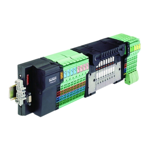
Figure 1: Type 8644 AirLINE Siemens
english
Type 8644

11
System Description
The Type 8644 Bürkert AirLINE is an electrical and pneumatic automation system which was developed for use in
the control cabinet or switch box. In a continuous system all electronic and pneumatic components are standardized,
enabling pneumatic, electric and electronic modules with various functions to be combined very easily with each
other by the observation of simple rules. All components are connected by a locking mechanism. At the same time
the required electrical connections are also established. For example, valves and power outputs can be combined
with one field bus connection only. A large number of electrical modules (terminals) can be combined very easily
with the valves mounted on special pneumatic modules (valve discs).
In its minimum configuration the system consists of the interface module IM151, a power module and the valve block.
Electronic modules of the ET200S system can be installed before and after the valve block. A power module must
always be provided after the interface module and without fail before the valve block. If the configuration requires
electronic modules after the valve block, a power module must be placed without fail after the valve block or before
the electronic modules, as the power supply voltage must be fed again. The maximum configuration of the decen-
tralized peripheral device comprises 64 nodes (including interface module, power modules, peripheral modules and
pneumatic base modules).
In its maximum configuration the valve block comprises 64x 11 mm (ME02) add-on dimension valves and 32x 16.5 mm
(ME03) add-on dimension valves which function monostably. If the configuration of the valve block also provides for
valves of Type 0461, a maximum of 24x 16.5 mm add-on dimension valves is authorized.
The ET200S supports the removal and insertion of modules during operation (RUN operating state). The function
module can be removed during operation the same as the electronic modules of the ET200S. However, the oper-
ating pressure must be switched off beforehand! To do this, it is essential to observe Chapter “7. Structure and
function of the modules”.
5.3. Structure of the system
Field bus
Central control
(e.g. PLC)
Interface
module
IM151
PM-E
DC
24V
PM-E
DC
24V
PM-E
DC
24V
Electronic modules
Electronic modules
Connection module
Connection module
Valve disc
Valve disc
2x
2x
4x
Valve disc
Valve
Valve
Field bus node 2
Field bus node ...
Field bus node n
Electronic
base module
Pneumatic
base module
Valve block
Figure 2: Schematic diagram of the Bürkert AirLINE system
english
Type 8644

12
System Description
5.4. Characteristic features and advantages
5.4.1. Characteristic features of AirLINE
• Easy to handle
• Function block-oriented structure of the switch box or control cabinet
• Automatic setup of potential groups, electric, data, and safety circuits
• Open, flexible and modular structure
• Combination of the valve discs and terminals in different granularity (2-fold, 4-fold,...) for space-optimized
station structure
5.4.2. Advantages of AirLINE
• Flow-optimized valve structure:
- Pressure range of vacuum up to 10 bar
- Flow-rate of approx. 300 l/min or 700 l/min with a valve width of 10 mm or 16 mm
• Integration of non-return valves in pneumatic base module (optional)
• Long service life thanks to flipper technology with oiled and unoiled air
• Simple combination of different functions, configuration and expansion thanks to high modularity
• Numerous valve functions: 3/2, 5/2 (monostable, bistable) and 5/3-way functions
• Mechanical emergency manual override
• Different pressure stages possible in one chain
• Integration of pressure gauges to indicate operating pressure
• Centralized compressed-air supply via connection modules on both sides, as well as intermediate feed
possible
english
Type 8644

13
System Description
5.5. Diagram of the valve block
Supply and vent connections
Working connections
4-fold valve disc
2-fold valve disc
Intermediate feed
Connection
module on right
Panel (optional pressure gauge to indicate
operating pressure on the station)
2-fold valve disc
Connection
module on left
Figure 3: Diagram of the modules of the Bürkert AirLINE system
english
Type 8644

14
System Description
5.6. Exploded drawing
5.6.1. Exploded drawing - add-on dimension 11 mm
Siemens
termination module
Siemens
field bus node
Siemens
power module
ME02
ME02
4-fold valve disc
ME02
2-fold valve disc
2-fold valve disc
ME02
M P11
Bulkhead
Type 0460
Type 6525
Type 6524
(2x3/2-way) Type 6524
Cover plate
Figure 4: Exploded drawing - add-on dimension 11 mm
english
Type 8644

15
System Description
5.6.2. Exploded drawing - add-on dimension 16.5 mm
Siemens
field bus node
Siemens
termination module
Siemens
power module
ME03
4-fold valve disc
ME03
2-fold valve disc
3-fold valve disc
2-fold valve disc
ME03
Accessories
ME03
MP12
Cover
Cover plate Type 0461
Type 6525
Type 6524
Type 6527
Type 6526
Figure 5: Exploded drawing - add-on dimension 16.5 mm
english
Type 8644

16
Technical Data
6. TECHNICAL DATA
6.1. Operating Conditions
WARNING!
Risk of injury!
Malfunction if used outside!
• Do not use Type 8644 AirLINE system outdoors and avoid heat sources which may cause the permitted tem-
perature range to be exceeded.
Permitted temperatures
Storage temperature: -20 ... +60 °C
Permitted air humidity: 75% on average, 85% occasionally
Permitted air pressure
Operation: 80 kPa to 106 kPa (up to 2,000 m above sea level)
Storage / transport: 70 kPa to 106 kPa (up to 3,000 m above sea level)
Protection class: Class 3 in accordance with VDE 106, IEC 60536
Protection class: IP20 in accordance with IEC 60529
6.2. Technical data of the entire system
Electrical power supply
Nominal voltage 24 V / DC
Tolerance -15 % / +20 %
Valve types: 0460, 0461 -10 % / +10 %
Valve type: 6524 (2 x 3/2-way) -15 % / +10 %
Current carrying capacity
Valve block (via connection module on left): max. 2.5 A
Valve type Valve flow
before power reduction after power reduction
6524 43 mA 28 mA
6524 (2 x 3/2-way) 43 mA 18 mA
6525 43 mA 28 mA
6526 (1W / 2 W) 42 / 85 mA 33 / 52 mA
6527 (1W / 2 W)
0460 41 mA -
0461 41 mA -
english
Type 8644

17
Technical Data
Max. power consumption
Logic current I_Log = I_Log_FBKN + ΣI_Module
I_Log Power consumption in the logic area
I_Log_FBKN Proportionate current in the field bus node ET200S max. 150 mA
I_Module Proportionate current in the logic area of the electronic base modules
max 10 mA each
Field bus node see Siemens handbook
The permitted ambient temperature depends on the modules used. The most critical module is essential
during assembly.
Module with: Valve type: 6524, 6525, 6526, 6527 0 ... +55° C
Module with: Valve type: 0460, 0461 0 ... +50° C
6.3. Technical Data of the valve block
Nominal operating mode Long-term operation (100 % ED)
Protection class (in terminal design) IP20
Protection class 3 in accordance with VDE 0580
Total current depends on electrical connection technology, expansion stage and control
Add-on dimension 11 mm
Operating principle
Valve
C/D (3/2-way)
Type 6524
2XC (2 x 3/2-way)
Type 6524
L/N (5/3-way)
Type 0460***
Operating principle
Valve
H (5/2-way)
Type 6525
-H (5/2-impulse)
Type 0460
Flow-rate 300 l/min 300 l/min 200 l/min
Pressure range
(with P shut-off)
2.5 ... 7 bar
5 – 7 bar
2.5 ... 7 bar 2.5 ... 7 bar
Output 1 W
*
2 x 1 W
with power reduction
2 x 0.9 W
Current before
power reduction
43 mA 2 x 43 mA 41 mA
Current after
power reduction
28 mA 2 x 18 mA -
Valve locations (max.) 64 32 32
Electrical modules 2-fold, 4-fold
monostable
2-fold 2 x monostable 2-fold bistable
Pneumatic modules 2-fold 2-fold bistable 2-fold bistable
english
Type 8644

18
Technical Data
Ambient temperature 0 ... +55 °C 0 ... +55 °C 0 ... +55 °C
Operating voltage 24 V / DC, -15 % / +20 % tolerance**,
Residual ripple for field bus interface 5 %
* Power reduction (in the module)
** For the Ex-version maximum +10 %
*** The following restrictions apply to the power supply tolerances of the entire system (see Technical Data of the
entire system): Valve type: 0460 ± 10 %
Add-on dimension 16.5 mm
Operating principle
Valve
C/D (3/2-way)
Type 6526
L/N (5/3-way)
Type 0461***
Operating principle
Valve
H (5/2-way)
Type 6527
H (5/2-impulse)
Type 0461
Flow-rate 700 l/min 500 l/min
Pressure range
(with P shut-off)
2 ... 10 bar 2.5 ... 7 bar
Output 1 W 2 W 2 x 1 W
Current before
power reduction
42 mA 85 mA 41 mA
Current after
power reduction
33 mA 52 mA -
Valve locations (max.) 32 24
Electrical modules 2-fold, 3-fold*, 4-fold 2-fold bistable
Pneumatic modules 2-fold, 3-fold*, 4-fold 2-fold bistable
Ambient temperature 0 ... +55° C 0 ... +55° C
Operating voltage 24 V / DC, -15 % / +20 % tolerance**,
Residual ripple for field bus interface 5 %
* 3 x 10 mm valves for add-on dimension of 16.5
** For the Ex-version maximum +10 %
*** The following restrictions apply to the power supply tolerances of the entire system (see Technical Data of the
entire system): Valve type: 0461 ± 10 %
Interface (PROFIBUS)
PROFIBUS Copper line (RS-485), connected via PROFIBUS plug,
supply isolated, shielding connected galvanically to the functional earth
Recommended cable lengths see PROFIBUS system data
english
Type 8644

19
Technical Data
6.4. Pneumatic data of the connection modules
Permitted temperature
(storage / transport) -20 ... +60° C
Permitted air humidity
(operation) 75 % on average, 85 % occasionally
CAUTION!
In the range of 0 – +55 °C take suitable measures against increased air humidity (> 85 %).
Slight condensation may occasionally occur on the external housing for a brief period, e.g. if the feed of a
vehicle is brought into a closed room.
Permitted air pressure
operation: 80 kPa to 106 kPa (up to 2,000 m above sea level)
Storage / transport: 70 kPa to 106 kPa (up to 3,000 m above sea level)
Protection class Class 3 in accordance with VDE 106, IEC 60536
Protection class IP20 in accordance with IEC 60529
6.4.1. Dimensioning of the connection modules
ME02 left ME03 left ME02 middle ME03 middle
Housing dimensions
(width x height x depth)
67 x 73 x 125 mm
(including catch
hook)
80 x 95 x 142 mm
(including catch
hook)
50 x 71 x 119 mm
(including catch
hook)
62 x 93 x 142 mm
(including catch
hook)
Weight 220 g 400 g 118 g 335 g
ME02 right ME03 right
Housing dimensions
(width x height x depth)
51 x 73 x 119 mm 61 x 95 x 142 mm
Weight 220 g 390 g
english
Type 8644

20
Technical Data
6.4.2. Performance features from the point of view of the entire
system
Connection module on left (ME02, ME03)
The connection module on left is electrically passive
→logical no process image, therefore no address is required
→mechanical ME02 - 47 mm installation dimension
ME03 - 56 mm installation dimension
→electrical no power consumption
→fluid left restriction of the valve block, left feed
Connection module in middle (ME02, ME03)
The intermediate feed is electrically passive
→logical no process image, therefore no address is required
→mechanical ME02 - 33 mm add-on dimension
ME03 - 42 mm add-on dimension
→electrical no power consumption
→fluid additional feed
Connection module on right
The connection module on right is electrically passive
→logical no process image, therefore no address is required
→mechanical ME02 - 47 mm installation dimension
ME03 - 56 mm installation dimension
→electrical no power consumption
→fluid right restriction of the valve block, right feed
english
Type 8644
Other manuals for 8644 AirLINE
7
Table of contents
Other Burkert Control System manuals

Burkert
Burkert ME02 Installation and operating instructions

Burkert
Burkert 5413 Series User manual

Burkert
Burkert 8644 AirLINE User manual

Burkert
Burkert 8644 AirLINE User manual

Burkert
Burkert 8644 AirLINE User manual

Burkert
Burkert 3232 User manual

Burkert
Burkert 8644 AirLINE User manual

Burkert
Burkert NAMUR 6517 User manual

Burkert
Burkert 8624 User manual