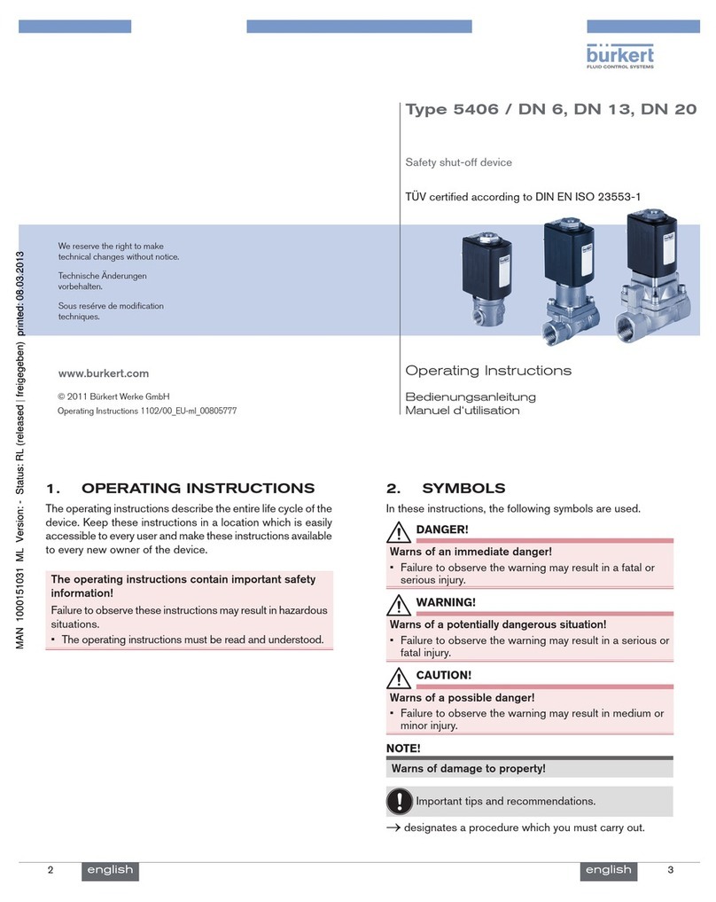
Burkert 0127 User manual

www.burkert.com
We reserve the right to make
technical changes without notice.
Technische Änderungen
vorbehalten.
Sous resérve de modification
techniques.
© 2008 - 2009 Bürkert Werke GmbH & Co. KG
Operating Instructions 0905/04_EU-ml_00893191
Operating Instructions
Bedienungsanleitung
Instructions de Service
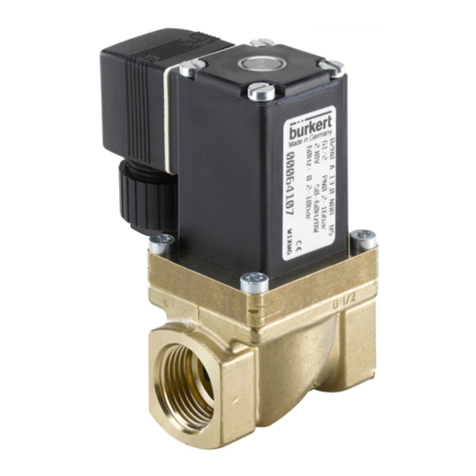
Rocker valve
2/2 or 3/2-way solenoid valve
2/2 oder 3/2-Wege Magnetventil
Vanne magnétique 2/2 ou 3/2
english
2
The operating instructions describe the entire life cycle of the
device. Keep these instructions in a location which is easily
accessible to every user and make these instructions available
to every new owner of the device.
Warning!
Important Safety Information!
Failure to observe these instructions may result in hazard-
ous situations.
The operating instructions must be read and under-•
stood.
english 3
The following symbols are used in these instructions.
Danger!
Warns of an immediate danger!
Failure to observe the warning may result in a fatal or•
serious injury.
Warning!
Warns of a potentially dangerous situation!
Failure to observe the warning may result in a serious or•
fatal injury.
Caution!
Warns of a possible danger!
Failure to observe this warning may result in a moder-•
ately severe or minor injury.
Caution! (without hazard symbol)
Warns of damage to property!
Important tips and recommendations for safe and
problem-free operation of the device.
designates a procedure which you must carry out.
→

english
4
Warning!
Incorrect use of the solenoid valve Type 0127 may be
a hazard to people, nearby equipment and the the sur-
rounding area.
Type 0127 must not be used outside.•
The permissible data, the operating and application con-•
ditions specified in the operating instructions and on the
rating plate must be observed during use.
Correct transportation, correct storage and installation,•
and careful operation and maintenance are essential for
reliable and problem-free operation.
Use Type 0127 only as instructed.•
The solenoid valve Type 0127 is not to be used in areas •
where there is a risk of explosion.
Do not introduce any aggressive or flammable media into •
the system's media connections.
Do not subject the housing to mechanical loads.•
Do not make any external modifications to the device •
housings.
english 5
Danger!
Risk of injury from high pressure!
Before loosening the lines and valves, turn off the pressure•
and vent the lines!
Risk of electric shock.
Risk of electric shock when reaching into the equipment.
Before starting work, always switch off the power supply•
and safeguard to prevent re-activation!
Observe applicable accident prevention and safety regula-•
tions for electrical equipment!
Risk of burns/danger of fire during long-term opera-
tion!
The device may become very hot during long-term opera-
tion.
A device that has already been in operation for an ex-•
tended period of time must only be handled with safety
gloves.
Keep readily flammable materials and media away from•
the device.
english
6
Warning!
Risk of injury from unintentional activation.
Take appropriate measures to prevent unintentional•
activation!
Warning!
Risk of injury during installation and maintenance work.
This work may be carried out by authorised technicians•
only and with the appropriate tools!
After an interruption in the power supply or pneumatic•
supply, ensure that the process is restarted in a defined
or controlled manner!
Caution!
The general rules of technology apply to applications
planning and operation of the device!
Failure to observe these rules may result in injuries and/
or damage to the device and possibly the area around it
as well.
Observe the general rules of technology!•
english 7
Operate the device only when it is in perfect condition
and in accordance with the operating instructions.
Failure to observe this operating manual and its operating in-
structions as well as unauthorised tampering with the device
release us from any liability and also invalidte the warranty
covering the device and accessories!
Caution!
Electrostatic sensitive components/modules!
The device contains electronic components which react
sensitively to electrostatic discharge (ESD). Contact with
electrostatically charged persons or objects is hazardous
to these components. In the worst case scenario, they will
be destroyed immediately or will fail after start-up.
Observe the requirements in accordance with EN 10001 – 1
to minimise or avoid the possibility of damage caused by
sudden electrostatic discharge.
Also ensure that electronic components do not come into
contact with a nearby power supply.
Type 0127

english
8
Check immediately upon receipt of delivery that the contents
are not damaged and that they correspond to the type and
quantity as indicated on the delivery note or packing list.
If there are any discrepancies, please contact us immedi-
ately.
Germany
Contact address:
Bürkert Fluid Control Systems
Sales Center
Chr.-Bürkert-Str. 13-17
D-74653 Ingelfingen
Tel.: +49 (0)7940 - 10 91 111
Fax: +49 (0)7940 - 10 91 448
E-mail: [email protected]
International
Contact addresses can be found on the final pages of the
printed operating instructions.
And also on the internet at:
www.burkert.com
Bürkert Company Locations
english 9
This document contains no promise or guarantee. Please
refer to our general terms of sales and delivery. The warranty
is only valid if the device valve Type 0127 is used as intended
in accordance with the specified application conditions.
The warranty extends only to defects in the Type
0127 and its components.
We accept no liability for any kind of collateral
damage which can occur due to failure or malfunc-
tion of the device.
The operating instructions and data sheets for Type 0127
can be found on the Internet at:
www.burkert.com
Documentation Manuals / Data
sheets Type 0127
The complete documentation is also available on CD which
can be ordered by quoting part no. 804625
english
10
Type 0127
The valve is modular in design and can be supplied with dif-
ferent line connections according to the application case. It
can be used individually and in blocks.
Warning!
Risk of injury
Malfunction if used outside!
Do not use Type 0127 outside and avoid heat sources•
which may cause the permitted temperature range to
be exceeded.
Ambient temperature 0 ... +55 °C
Medium temperature FFKM 0 ... +50 °C
FKM 0 ... +60 °C
english 11
Media neutral and aggressive liquids and
gases which do not corrode the
housings and seal materials
technical vacuum
Protection class IP54 with wires and individual device
socket
IP20 with multi-device socket
CE mark conforms to EMC Directive 2004/108/EEC
Dimensions see data sheet
Housing material PVDF, ETFE, PEEK
Sealing material FFKM, FKM
(EPDM on request)
Type 0127

english
12
Operating principles
A
A
P/NC
2/2-way valve, direct action,
closed with no current
B
B
P/NO
2/2-way valve, direct action,
opened with no current
I
A
P/NC
2/2-way valve, direct action,
closed with no current, any
direction of flow
T
A in/out
P/NC R/NO
3/2-way valve, direct-acting,
all-purpose
Pressure range vac ... 2 bar
Line connections Threaded connection G1/8,
NPT1/8 or UNF1/4-28
Flanged connection
Hose connection
Note the information specified on the rating plate for
voltage, type of current, and pressure.
english 13
Made in Germany
00450000 W14UN
CE
0127 T 1.6 FKM PD
G1/8 PN0-2bar
24V AC/DC 3W
Ident. no.
Voltage/frequency output
Nominal connection pressure
Type
Operating principle
Nominal width
Seal material
Housing material
english
14
Operating voltage 12 V DC
24 V DC
24 V UC
110-120 V UC
220-240 V UC
Voltage tolerance ± 10 %
Nominal power
12-24 V 3.0 W
110-240 V 3.4 W
Nominal operating mode Long-term operation,
duty cycle 100 %
for block assembly if temperatures of media or
surrounding area above +40 °C:
intermittent duty 40% (10 min)
Note the information specified on the rating plate for
voltage, type of current, and pressure.
english 15
Warning!
Risk of injury when installing the valve.
This work may be carried out by authorised technicians•
only and with the appropriate tools!
After an interruption in the power supply or pneumatic•
supply, ensure that the process is restarted in a defined
or controlled manner!
Danger!
Danger – high pressure!
Danger of severe injuries from reaching into the system.
Before loosening the lines and valves, turn off the pressure•
and vent the lines.
Installation position: any position, preferably with the drive
facing up.
Type 0127

english
16
Installation
Before installation, clean any possible dirt off the pipe-
→
lines and flange connections.
If required, install a dirt trap to prevent malfunctions.
→
Mesh size: 5 µm
Observe the direction of flow of the valve.
Operating principle*
A / I
T
B
* seealsothedescriptionoftheoperatingprinciplesinthechap-
terentitled"PneumaticData"
english 17
Identification of the valve connections on the housing:
NO Normally Open Connection normally open
for WWB
NC Normally Closed Connection normally closed,
for WWA or I
IN/OUT for pressure connection (distributor) or
work connection (mixer), for WWT
The valve housing must not be twisted by the fasten-
ing screws or by screwing in the connecting nipples
too far!
The housings with threaded or hose connection have fixing
eyelets for the screw connection from above with M3 and from
below with self-tapping screws BZ 3.9 x ... DIN 7971.
Housing with threaded connection:
Use PTFE tape as sealing material
→
Screw in the connecting thread by hand only →
Housing with hose connection:
Use flexible silicone or FKM hose with 1.6-2 mm inner
→
diameter
english
18
Valve with flanged connection:
Remove the locking plate (coloured orange).
→
Do not remove the flanged plate!
Warning!
Danger – escaping medium!
Leaking connections if seals not seated properly, if connec-
tion plate uneven or if surface quality of the connection plate
inadequate.
Make certain the seals included with delivery are prop-•
erly seated in the valve.
Ensure that the connection plate is even.•
Ensure that the surface quality of the connection plate is•
adequate.
Insert the seal into the valve.
→
Caution!
If the tightening torque is too great, the device may
be damaged!
Observe the max. tightening torque of the screws.•
english 19
Screw in screws to
0.3 ± 0.05 Nm
Caution:
Do not remove
flanged plate !
Attach valve to the connection plate. →
Dimensional drawing for connection plate:
NO
IN/OUT
NC
M2.5 min 8.5 deep
max. ø2
18
21.5
10.5
Arrangement of the bores:
3-way 2-way DF 2-way PEEK
Type 0127

english
20
Danger!
Risk of electric shock when reaching into the
equipment!
Before starting work, always switch off the power supply•
and safeguard to prevent re-activation!
Observe applicable accident prevention and safety•
regulations for electrical equipment!
Note the voltage and current type as specified on
the rating plate.
Voltage tolerance±10%
Connection to device socket:
Danger!
Risk of electric shock if protective conductor not
connected!
Always connect protective conductor!•
Earthing connection (if fitted): Middle plug tab
Ensure that the flat seal is seated correctly for the
electrical connection to the device socket.
english 21
Device socket
Type 1054
Flat seal
Valve
max. tightening torque: 0.4 Nm
Caution!
If the tightening torque is too great, the device may
be damaged!
Observe the max. tightening torque of the screw.•
Screw device socket to valve to a max. tightening
→
torque of 0.4 Nm.
Alternative electrical connection:
Two individual wires
english
22
The valve is maintenance-free under normal operating condi-
tions.
If malfunctions occur, check
the line connections
→
the operating pressure →
the power supply and valve control. →
If the valve still does not switch, please contact your Bürkert
Service.
Caution!
Using the wrong accessories or replacement parts
may be dangerous!
Incorrect accessories and spare parts may cause injuries
and damage the device and the surrounding area.
Use only original accessories and original spare parts•
supplied by Bürkert GmbH & Co. KG.
Accessories and replacement parts available on request.
english 23
Caution!
Transport damage/Storage damage
Transport and store the device, protected from wet and•
dirty conditions, in shock-resistant packaging.
Avoid the effects of heat and cold which could result•
in temperatures above or below the permitted storage
temperature.
Storage temperature: -20 ... +65°C.•
Caution!
Damage to the environment caused by device com-
ponents contaminated with media.
Observe the relevant disposal and environmental protec-•
tion regulations.
Dispose of the device and packaging in an environmentally
→
friendly manner.
Observe national waste disposal regulations.
→
Type 0127

www.burkert.com
We reserve the right to make
technical changes without notice.
Technische Änderungen
vorbehalten.
Sous resérve de modification
techniques.
© 2008 - 2009 Bürkert Werke GmbH & Co. KG
Operating Instructions 0905/04_EU-ml_00893191
Bedienungsanleitung
Deutsch
Wippenventil
2/2 oder 3/2-Wege Magnetventil
deutsch
26
Die Bedienungsanleitung beschreibt den gesamten Lebenszy-
klus des Gerätes. Bewahren Sie diese Anleitung so auf, dass
sie für jeden Benutzer gut zugänglich ist und jedem neuen
Eigentümer des Gerätes wieder zur Verfügung steht.
Warnung!
Wichtige Informationen zur Sicherheit!
Das Nichtbeachten der Bedienungsanleitung und der Sicher-
heitshinweise kann zu gefährlichen Situationen führen.
Die Bedienungsanleitung muss gelesen und verstan-•
den werden.
27
deutsch
In dieser Anleitung werden folgende Darstellungsmittel
verwendet.
gefahr!
Warnt vor einer unmittelbaren Gefahr!
Bei Nichtbeachtung sind Tod oder schwere Verlet-•
zungen die Folge.
Warnung!
Warnt vor einer möglicherweise gefährlichen Situation!
Bei Nichtbeachtung können schwere Verletzungen oder•
Tod die Folge sein.
Vorsicht!
Warnt vor einer möglichen Gefährdung!
Nichtbeachtung kann mittelschwere oder leichte Verlet-•
zungen zur Folge haben.
Vorsicht! (ohne Gefahrsymbol)
Warnt vor Sachschäden!
Wichtige Tipps und Empfehlungen für die Sicherheit
und einwandfreie Funktion des Gerätes.
markiert einen Arbeitsschritt den Sie ausführen müssen.
→

deutsch
28
Warnung!
Bei nicht bestimmungsgemäßem Einsatz des Magnet-
ventils Typ 0127 können Gefahren für Personen, Anlagen
in der Umgebung und die Umwelt entstehen.
Typ 0127 darf nicht im Außenbereich eingesetzt werden.•
Für den Einsatz sind die in der Bedienungsanleitung und•
auf dem Typschild spezifizierten zulässigen Daten, sowie
die Betriebs- und Einsatzbedingungen zu beachten.
Voraussetzungen für den sicheren und einwandfreien•
Betrieb sind sachgemäßer Transport, sachgemäße La-
gerung und Installation sowie sorgfältige Bedienung und
Instandhaltung.
Setzen Sie Typ 0127 nur bestimmungsgemäß ein.•
Das Magnetventil Typ 0127 darf nicht in explosionsgefähr-•
deten Bereichen eingesetzt werden.
Speisen Sie in die Medienanschlüsse des Systems keine •
aggressiven oder brennbaren Medien ein.
Belasten Sie das Gehäuse nicht mechanisch.•
Nehmen Sie keine äußerlichen Veränderungen an den •
Gerätegehäusen vor.
29
deutsch
gefahr!
Verletzungsgefahr durch hohen Druck.
Vor dem Lösen von Leitungen und Ventilen, den Druck•
abschalten und Leitungen entlüften!
Gefahr durch elektrische Spannung.
Gefahr eines Stromschlags bei Eingriffen in die Anlage.
Schalten Sie vor Beginn der Arbeiten in jedem Fall die•
Spannung ab und sichern Sie diese vor Wiedereinschal-
ten!
Beachten Sie die geltenden Unfallverhütungs- und Si-•
cherheitsbestimmungen für elektrische Geräte!
Verbrennungsgefahr/Brandgefahr bei Dauerbetrieb!
Das Gerät kann im Dauerbetrieb sehr heiß werden.
Ein Gerät das bereits länger in Betrieb ist nur mit Schutz-•
handschuhen anfassen.
Leicht brennbare Stoffe und Medien vom Gerät fern-•
halten.
deutsch
30
Warnung!
Verletzungsgefahr durch unbeabsichtigtes Betätigen.
Verhindern Sie durch geeignete Maßnahmen ein unbe-•
absichtigtes Betätigen!
Warnung!
Verletzungsgefahr bei Montage- und Wartungsarbeiten.
Diese Arbeiten dürfen nur durch autorisiertes Fach-•
personal und mit geeignetem Werkzeug durchgeführt
werden!
Gewährleisten Sie nach einer Unterbrechung der elek-•
trischen oder pneumatischen Versorgung einen definierten
oder kontrollierten Wiederanlauf des Prozesses!
Vorsicht!
Für die Einsatzplanung und den Betrieb des Gerätes
gelten die allgemeinen Regeln der Technik!
Beachten Sie die Regeln nicht, können Verletzungen ent-
stehen und/oder das Gerät, ggf. auch dessen Umgebung,
können beschädigt werden.
Halten Sie die allgemeinen Regeln der Technik ein!•
31
deutsch
Betreiben Sie das Gerät nur in einwandfreiem Zustand
und unter Beachtung der Bedienungsanleitung.
Bei Nichtbeachtung dieser Bedinungsanleitung und ihrer
Hinweise sowie bei unzulässigen Eingriffen in das Gerät
entfällt jegliche Haftung unsererseits, ebenso erlischt die
Gewährleistung auf Geräte und Zubehörteile!
Vorsicht!
Elektrostatisch gefährdete Bauteile/Baugruppen!
Das Gerät enthält elektronische Bauelemente, die gegen
elektrostatische Entladung (ESD) empfindlich reagieren.
Berührung mit elektrostatisch aufgeladenen Personen oder
Gegenständen gefährdet diese Bauelemente. Im schlimm-
sten Fall werden sie sofort zerstört oder fallen nach der
Inbetriebnahme aus.
Beachten Sie die Anforderungen nach EN 100015 - 1, um
die Möglichkeit eines Schadens durch schlagartige elektro-
statische Entladung zu minimieren bzw. zu vermeiden.
Achten Sie auch darauf, dass Sie elektronische Bauelemente
nicht bei anliegender Versorgungsspannung berühren.
Typ 0127
deutsch
32
Überzeugen Sie sich unmittelbar nach Erhalt der Sendung,
dass der Inhalt nicht beschädigt ist und in Art und Umfang mit
dem Lieferschein bzw. der Packliste übereinstimmt.
Bei Unstimmigkeiten wenden Sie sich bitte umgehend an
uns.
Deutschland
Kontaktadresse:
Bürkert Fluid Control Systems
Sales Center
Chr.-Bürkert-Str. 13-17
D-74653 Ingelfingen
Tel. : +49 (0) 7940 - 10 91 111
Fax: +49 (0) 7940 - 10 91 448
E-mail: [email protected]
International
Die Kontaktadressen finden Sie auf den letzten Seiten der
gedruckten Bedienungsanleitung.
Außerdem im Internet unter:
www.burkert.com
Bürkert Company Locations
33
deutsch
Diese Druckschrift enthält keine Garantiezusagen. Wir ver-
weisen hierzu auf unsere allgemeinen Verkaufs- und Liefer-
bedingungen. Voraussetzung für die Gewährleistung ist der
bestimmungsgemäße Gebrauch des Magnetventils Typ 0127
unter Beachtung der spezifizierten Einsatzbedingungen.
Die Gewährleistung erstreckt sich nur auf die Feh-
lerfreiheit des Typs 0127 und seiner Bauteile.
Für Folgeschäden jeglicher Art, die durch Ausfall
oder Fehlfunktion des Gerätes entstehen könnten,
wird keine Haftung übernommen.
Bedienungsanleitungen und Datenblätter zum Typ 0127
finden Sie im Internet unter:
www.buerkert.de
Technische Daten Bedienungsanlei-
tungen / Datenblätter Typ 0127
Desweiteren steht eine komplette Dokumentation auf CD
bereit, die unter der Identnummer 804625 bestellt werden
kann.
deutsch
34
Typ 0127
Das Ventil ist modular aufgebaut und kann je nach Einsatzfall
mit verschiedenen Leitungsanschlüssen geliefert werden.
Es ist einzeln und auch auf Blöcken einsetzbar.
Warnung!
Verletzungsgefahr
Funktionsausfall bei Einsatz im Außenbereich!
Setzen Sie den Typ 0127 nicht im Außenbereich ein und•
vermeiden Sie Wärmequellen, die zur Überschreitung des
zulässigen Temperaturbereichs führen können.
Umgebungstemperatur 0 ... +55 °C
Mediumstemperatur FFKM 0 ... +50 °C
FKM 0 ... +60 °C
35
deutsch
Medien neutrale und aggressive Flüssigkeiten und
Gase, die Gehäuse und Dichtwerkstoffe
nicht angreifen
technisches Vakuum
Schutzart IP54 mit Litzen und Einzelgerätesteckdose
IP20 mit Mehrfachgerätesteckdose
CE - Zeichen konform bzgl. EMV-Richtlinie 2004/108/EG
Maße siehe Datenblatt
Gehäusematerial PVDF, ETFE, PEEK
Dichtungsmaterial FFKM, FKM
(EPDM auf Anfrage)
Typ 0127

deutsch
36
Wirkungsweisen
A
A
P/NC
2/2 Wege-Ventil, direktwirkend,
stromlos geschlossen
B
B
P/NO
2/2-Wege-Ventil, direktwirkend,
stromlos geöffnet
I
A
P/NC
2/2-Wege-Ventil, direktwirkend,
stromlos geschlossen,
Durchflussrichtung beliebig
T
A in/out
P/NC R/NO
3/2-Wege-Ventil, direktwirkend,
universell einsetzbar
Druckbereich vac ... 2 bar
Leitungsanschlüsse Gewindeanschluss G1/8,
NPT1/8 oder UNF1/4-28
Flanschanschluss
Schlauchanschluss
Beachten Sie die auf dem Typschild angegebene
Daten für Spannung, Stromart und Druck.
37
deutsch
Made in Germany
00450000 W14UN
CE
0127 T 1,6 FKM PD
G1/8 PN0-2bar
24V AC/DC 3W
Ident-Nr.
Spannung-Frequenz-Leistung
Anschluss-Nenndruck
Typ
Wirkungsweise
Nennweite
Dichtwerkstoff
Gehäusewerkstoff
deutsch
38
Betriebspannung 12 V DC
24 V DC
24 V UC
110-120 V UC
220-240 V UC
Spannungstoleranz ± 10 %
Nennleistung
12-24 V 3,0 W
110-240 V 3,4 W
Nennbetriebsart Dauerbetrieb, ED 100 %
bei Blockmontage falls Temperaturen von Medien oder
Umgebung über +40 °C: Aussetzbe-
trieb 40% (10min)
Beachten Sie die auf dem Typschild angegebene
Daten für Spannung, Stromart und Druck.
39
deutsch
Warnung!
Verletzungsgefahr bei der Montage des Ventils.
Diese Arbeiten dürfen nur durch autorisiertes Fach-•
personal und mit geeignetem Werkzeug durchgeführt
werden!
Gewährleisten Sie nach einer Unterbrechung der elek-•
trischen oder pneumatischen Versorgung einen definierten
oder kontrollierten Wiederanlauf des Prozesses!
gefahr!
Gefahr durch hohen Druck!
Akute Verletzungsgefahr bei Eingriffen in die Anlage.
Vor dem Lösen von Leitungen und Ventilen, Druck abschal-•
ten und Leitungen entlüften.
Einbaulage: beliebig, vorzugsweise Antrieb nach oben.
Typ 0127

deutsch
40
Montage
Vor der Montage Rohrleitungen und Flanschanschlüsse
→
von eventuellen Verschmutzungen säubern.
Zum Schutz vor Störungen gegebenenfalls einen
→
Schmutzfänger einbauen. Maschenweite:
5 µm
Beachten Sie die Durchflussrichtung des Ventils.
Wirkungsweise*
A / I
T
B
* sieheauchdieBeschreibungderWirkungsweiseimKapitel
„PneumatischeDaten“
41
deutsch
Kennzeichnung der Ventilanschlüsse auf dem Gehäuse:
NO Normally Open Anschluss stromlos offen
bei WWB
NC Normally Closed Anschluss stromlos ge-
schlossen, bei WWA bzw. I
IN/OUT für Druckanschluss (Verteiler) bzw.
Arbeitsanschluss (Mischer), bei WWT
Das Ventilgehäuse darf durch die Befestigungs-
schrauben bzw. durch übermäßiges Eindrehen der
Anschlussnippel nicht verspannt werden!
Die Gehäuse mit Gewinde- oder Schlauchanschluss haben
Befestigungsaugen für die Verschraubung von oben mit M3
bzw. von unten mit Blechschrauben BZ 3,9 x ... DIN 7971.
Gehäuse mit Gewindeanschluss:
Als Dichtungsmaterial PTFE-Band verwenden
→
Die Anschlussgewinde nur von Hand einschrauben →
Gehäuse mit Schlauchanschluss:
Flexibler Silikon- oder FKM-Schlauch mit 1,6-2mm
→
Innendurchmesser verwenden
deutsch
42
Ventil mit Flanschanschluss:
Die Verschlussplatte (orange eingefärbt) entfernen.
→
Flanschplatte nicht ablösen!
Warnung!
Gefahr durch Mediumsaustritt!
Undichte Anschlüsse bei ungenauem Sitz der Dichtungen,
bei unebener Anschlussplatte oder unzureichender Oberflä-
chengüte der Anschlussplatte.
Achten Sie bei den mitgelieferten Dichtungen auf den•
richtigen Sitz im Ventil.
Achten Sie auf die Ebenheit der Anschlussplatte.•
Achten Sie auf ausreichende Oberflächengüte der•
Anschlussplatte.
Die Dichtung in das Ventil einlegen.
→
Vorsicht!
Durch ein zu großes Anzugsmoment kann das Gerät
beschädigt werden!
Beachten Sie das max. Anzugsmoment der Schrauben.•
43
deutsch
Schrauben mit
0,3 ± 0,05 Nm
einschrauben
Achtung:
Flanschplatte nicht
ablösen !
Ventil auf der Anschlussplatte befestigen. →
Masszeichnung für Anschlussplatte:
NO
IN/OUT
NC
M2,5 min 8,5 tief
max. ø2
18
21,5
10,5
Anordnung der Bohrungen:
3-Wege 2-Wege PVDF 2-Wege PEEK
Typ 0127

deutsch
44
gefahr!
Gefahr durch elektrische Spannung bei Eingriffen in
die Anlage!
Schalten Sie vor Beginn der Arbeiten in jedem Fall die•
Spannung ab und sichern Sie diese vor Wiedereinschal-
ten!
Beachten Sie die geltenden Unfallverhütungs- und•
Sicherheitsbestimmungen für elektrische Geräte!
Spannung und Stromart laut Typschild beachten.
Spannungstoleranz ±10%
Anschluss mit Gerätesteckdose:
gefahr!
Gefahr durch elektrische Spannung bei nicht ange-
schlossenem Schutzleiter!
Schutzleiter immer anschließen!•
Erdungsanschluss (falls vorhanden): Mittlere Steckerfahne
Für den elektrischen Anschluss mit Gerätesteckdo-
se auf den richtigen Sitz der Flachdichtung achten.
45
deutsch
Gerätesteckdose
Typ 1054
Flachdichtung
Ventil
max. Anzugsmoment: 0,4 Nm
Vorsicht!
Durch ein zu großes Anzugsmoment kann das Gerät
beschädigt werden!
Beachten Sie das max. Anzugsmoment der Schraube.•
Gerätesteckdose mit Ventil mit einem max. Anzugsmo-
→
ment von 0,4 Nm verschrauben.
Alternativer Elektroanschluss:
zwei Einzellitzen
deutsch
46
Das Ventil arbeitet unter Normalbedingungen wartungsfrei.
Überprüfen Sie bei Störungen
die Leitungsanschlüsse
→
den Betriebsdruck →
die Spannungsversorgung und Ventilansteuerung →
Falls das Ventil dennoch nicht schaltet, wenden Sie sich bitte
an Ihren Bürkert-Service.
Vorsicht!
Gefahr durch falsches Zubehör und Ersatzteile!
Falsches Zubehör und Ersatzteile können Verletzungen und
Schäden am Gerät oder seiner Umgebung verursachen.
Verwenden Sie nur Originalzubehör sowie Originalersatz-•
teile der Firma Bürkert GmbH & Co. KG.
Zubehör und Ersatzteile auf Anfrage.
47
deutsch
Vorsicht!
Transportschäden/Lagerschäden
Transportieren und Lagern Sie das Gerät vor Nässe und•
Schmutz und gesichert in einer stoßfesten Verpackung.
Vermeiden Sie Hitze - und Kälteeinwirkungen, die zur•
Über- bzw. Unterschreitung der zulässigen Lagertempe-
ratur führen könnten.
Lagertemperatur: -20 ... +65 °C.•
Vorsicht!
Umweltschäden durch von Medien kontaminierte
Geräteteile.
Halten Sie die diesbezüglich geltenden Entsorgungsvor-•
schriften und Umweltbestimmungen ein.
Entsorgen Sie Gerät und Verpackung umweltgerecht.
→
Beachten Sie die nationalen Abfallbeseitigungsvor- →
schriften.
Typ 0127

www.burkert.com
We reserve the right to make
technical changes without notice.
Technische Änderungen
vorbehalten.
Sous resérve de modification
techniques.
© 2008 - 2009 Bürkert Werke GmbH & Co. KG
Operating Instructions 0905/04_EU-ml_00893191
Instructions de Service
Français
Soupape à balancier
Vanne magnétique 2/2 ou 3/2
français
50
Les instructions de service décrivent le cycle de vie complet
de l’appareil. Conservez ces instructions de sorte qu’elles
soient accessibles à tout utilisateur et à disposition de tout
nouveau propriétaire.
Avertissement !
Informations importantes pour la sécurité !
Le non-respect des instructions de service et des consignes
de sécurité peut mener à des situations dangereuses.
Les instructions de service doivent être lues et com-•
prises.
51
français
Les moyens de représentation suivants sont utilisés dans
les présentes instructions de service.
DAnger !
Met en garde contre un danger imminent !
Le non-respect peut entraîner la mort ou de graves•
blessures.
Avertissement !
Met en garde contre une situation éventuellement
dangereuse !
Le non-respect peut entraîner de graves blessures ou•
la mort.
Attention !
Met en garde contre un risque possible !
Le non-respect peut entraîner des blessures légères ou•
de moyenne gravité.
Attention ! (sans symbole de danger)
Met en garde contre des dommages matériels !
Conseils et recommandations importants pour la
sécurité et le parfait fonctionnement de l’appareil.
identifie une opération que vous devez effectuer.
→

français
52
Avertissement !
L’utilisation non conforme de la soupape magnétique,
type 0127 peut présenter des dangers pour les person-
nes, les installations proches et l’environnement.
Le type 0127 ne doit pas être utilisé à l’extérieur.•
Il convient de respecter les données admissibles spé-•
cifiées dans les instructions de service et sur la plaque
signalétique ainsi que les conditions d’exploitation et
d’utilisation.
Les conditions pour l’utilisation sûre et parfaite sont un•
transport, un stockage et une installation dans les règles
ainsi qu’une utilisation et maintenance parfaites.
Veillez à ce que l’utilisation du type 0127 soit toujours•
conforme.
La vanne magnétique type 0127 ne doit pas être utilisée •
dans des zones présentant des risques d’explosion.
N’alimentez pas les raccords de fluides du système en •
fluides agressifs ou inflammables.
Ne soumettez pas le boîtier à des contraintes mécani-•
ques.
N’apportez pas de modifications à l’extérieur du boîtier •
de l’appareil.
53
français
DAnger !
Danger dû à la haute pression !
Avant de desserrer les conduites et les vannes, coupez•
la pression et purgez l’air des conduites !
Danger présenté par la tension électrique.
Danger d’un choc électrique lors d’interventions dans
l’installation.
Avant d’effectuer des travaux, coupez toujours la tension et•
empêchez toute remise sous tension par inadvertance !
Veuillez respecter les réglementations en vigueur pour•
les appareils électriques en matière de prévention des
accidents ainsi qu’en matière de sécurité !
Risque de brûlures/d’incendie en fonctionnement
continu !
L’appareil peut devenir très chaud en fonctionnement
continu.
Portez toujours des gants de protection pour toucher un•
appareil ayant fonctionné pendant longtemps.
Tenez les substances et les fluides facilement inflamma-•
bles à l’écart de l’appareil.
français
54
Avertissement !
Risque de blessures par actionnement non intention-
nel.
Empêchez tout actionnement non intentionnel en prenant•
des mesures appropriées !
Avertissement !
Risque de blessures lors des travaux de montage et
de maintenance.
Ces travaux doivent être effectués uniquement par des•
techniciens qualifiés et habilités disposant de l’outillage
approprié !
Après une interruption de l’alimentation électrique ou•
pneumatique, garantissez un redémarrage défini ou
contrôlé du processus !
Attention !
Les règles générales de la technique sont d’applica-
tion pour planifier l’utilisation et utiliser l’appareil !
Si ces règles ne sont pas respectées, il peut s’ensuivre
des blessures et/ou des dommages sur l’appareil ou son
environnement.
Respectez les règles générales de la technique !•
55
français
Utilisez l’appareil uniquement en parfait état et en
respectant les instructions de service.
Le non-respect de ces instructions de service avec ses con-
signes ainsi que les interventions non autorisées sur l’appareil
excluent toute responsabilité de notre part et entraînent la
nullité de la garantie légale concernant les appareils et les
accessoires !
Attention !
Eléments/sous-groupes sujets aux risques électros-
tatiques !
L’appareil contient des éléments électroniques sensibles aux
décharges électrostatiques (ESD). Ces éléments sont affec-
tés par le contact avec des personnes ou des objets ayant
une charge électrostatique. Au pire, ils sont immédiatement
détruits ou tombent en panne après mise en service.
Respectez les exigences selon EN 100015 – 1 pour mini-
miser ou éviter la possibilité d’un dommage causé par une
soudaine décharge électrostatique.
Veillez également à ne pas toucher des éléments électroni-
ques lorsqu’ils sont sous tension.
Type 0127

français
56
Dès réception de l’envoi, assurez-vous que le contenu n’est
pas endommagé et correspond au bon de livraison ou à la liste
de colisage pour ce qui concerne le type et la quantité.
En cas de différences, veuillez nous contacter immédiate-
ment.
Allemagne
Adresse :
Bürkert Fluid Control Systems
Sales Center
Chr.-Bürkert-Str. 13-17
D-74653 Ingelfingen
Tél. : +49 (0)7940 - 10 91 111
Fax : +49 (0)7940 - 10 91 448
E-mail : [email protected]
International
Les adresses se trouvent aux dernières pages des instruc-
tions de service imprimées.
Egalement sur internet sous
www.burkert.com
Bürkert Company Locations
57
français
Cet imprimé ne contient aucune promesse de garantie. A cet
effet, nous renvoyons à nos conditions générales de vente
et de livraison. La condition pour bénéficier de la garantie
légale est l’utilisation conforme de l'appareil type 0127, dans
le respect des conditions d’utilisation spécifiées.
La garantie ne couvre que l’absence de défaut du
robinet à bille synthétique du type 0127 et de ses
composants.
Nous déclinons toute responsabilité pour les dom-
mages de toute nature qui résultent de la panne ou
du dysfonctionnement de l’appareil.
Vous trouverez les instructions de service et les fiches tech-
niques concernant le type 0127 sur Internet sous :
www.buerkert.fr
Fiches techniques Fiches techniques
/ manuel d'utilisation Type 0127
Par ailleurs, une documentation complète est disponible
sur CD, elle peut être commandée sous le numéro d'identi-
fication 804625.
français
58
Type 0127
La soupape est de construction modulaire et peut être fournie
selon l’utilisation prévue avec différents raccords de conduite.
Elle peut être utilisée seule et également sur des blocs.
Avertissement !
Risque de blessures
Panne lors de l’utilisation à l’extérieur !
N’utilisez pas le type 0127 à l’extérieur et évitez les sour-•
ces de chaleur susceptibles d’entraîner un dépassement
de la plage de température admissible.
Température ambiante 0 ... +55 °C
Température du fluide FFKM 0 ... +50 °C
FKM 0 ... +60 °C
59
français
Fluides Liquides neutres et agressifs ainsi
que gaz n’attaquant pas le matériau
du corps et du joint
vide technique
Type de protection IP54 avec torons et prise d’appareil
simple
IP20 avec prise multiple
Label CE conforme en ce qui concerne la directive
CEM 2004/108/CE
Dimensions Cf. fiche technique
Matériau du boîtier PVDF, ETFE, PEEK
Matériau d’étanchéité FFKM, FKM
(EPDM sur demande)
Type 0127

français
60
Modes d’action
A
A
P/NC
Soupape magnétique 2/2, à ac-
tion directe, fermée sans courant
B
B
P/NO
Soupape magnétique 2/2, à ac-
tion directe, ouverte sans courant
I
A
P/NC
Soupape à 2/2 voies, à action
directe, fermée sans courant,
sens du débit indifférent
T
A in/out
P/NC R/NO
Soupape à 3/2 voies, à action
directe, utilisation universelle
Plage de pression vac ... 2 bars
Raccords de conduite Raccord fileté G1/8,
NPT1/8 ou UNF1/4-28
Raccord à bride
Raccord de tuyau
Respectez les données indiquées sur la plaque
signalétique pour la tension, le type de courant et la
pression.
61
français
Made in Germany
00450000 W14UN
CE
0127 T 1,6 FKM PD
G1/8 PN0-2 bars
24 V AC/DC 3 W
N° ID
Tension / Fréquence / Puissance
Raccord-Pression nominale
Type
Mode d’action
Diamètre nominal
Matériau du joint
Matériau du boîtier
français
62
Tension de service 12 V DC
24 V DC
24 V UC
110-120 V UC
220-240 V UC
Tolérance de tension ± 10 %
Puissance nominale
12-24 V 3,0 W
110-240 V 3,4 W
Mode opératoire nominal Fonctionnement continu,
ED 100 %
en montage dos à dos Si les températures des fluides
ou de l’environnement dépassent
+40 °C : fonctionnement inter-
mittent 40 % (10 mn)
Respectez les données indiquées sur la plaque
signalétique pour la tension, le type de courant et la
pression.
63
français
Avertissement !
Risque de blessures lors du montage de la vanne.
Ces travaux doivent être effectués uniquement par des•
techniciens qualifiés et habilités disposant de l’outillage
approprié !
Après une interruption de l’alimentation électrique ou•
pneumatique, garantissez un redémarrage défini ou
contrôlé du processus !
DAnger !
Danger dû à la haute pression !
Risque important de blessures en cas d’interventions dans
l’installation.
Avant de desserrer les conduites et les vannes, coupez la•
pression et purgez l’air des conduites.
Position de montage : au choix, de préférence entraînement
vers le haut.
Type 0127

français
64
Montage
Avant le montage, nettoyer la tuyauterie et les raccor-
→
dements à bride afin d’enlever les éventuelles saletés.
Installez éventuellement un panier comme protection
→
contre les dysfonctionnements. Mailles : 5 µm
Respectez le sens du débit de la soupape.
Mode d’action*
A / I
T
B
* voirégalementladescriptiondumoded’actionauchapitre
«Caractéristiquespneumatiques»
65
français
Identification des raccords de soupape au boîtier :
NO Normally Open Raccord ouvert sans courant
pour WWB
NC Normally Closed Raccord fermé sans courant,
pour WWA ou I
IN/OUT pour raccord de pression (distributeur) ou
raccord de travail (mélangeur), pour WWT
Le boîtier de la soupape ne doit pas être trop serré
par les vis de fixation ou en vissant trop fort le raccord
de connexion !
Les boîtiers avec raccord fileté ou raccord de tuyau sont dotés
d’œils de fixation pour raccord vissé en haut avec M3 et par
le bas avec des vis à tôle BZ 3,9 x ... DIN 7971.
Boîtier avec raccord fileté :
Utilisez une bande PTFE comme matériau d’étanchéité
→
Vissez les raccords uniquement à la main →
Boîtier avec raccord de tuyau :
Utilisez un flexible en silicone ou en FKM d’un diamètre
→
intérieur de 1,6 à 2 mm
français
66
Soupape avec raccord à bride :
Enlevez la plaque de fermeture (couleur orange).
→
N’enlevez pas la plaque de bridage !
Avertissement !
Danger dû à la sortie de fluide !
Raccords non étanches dus à une mauvaise position des
joints, une plaque de raccordement non plane ou d’une qualité
de surface insuffisante.
Veillez au positionnement correct des joints fournis dans•
la vanne.
Veillez à la planéité de la plaque de raccordement.•
Veillez à une qualité de surface suffisante de la plaque•
de raccordement.
Placez le joint dans la soupape.
→
Attention !
L’appareil peut être endommagé par un couple de
serrage trop fort !
Respectez le couple de serrage maxi des vis.•
67
français
Vissez les vis à 0,3
± 0,05 Nm
Attention :
N’enlevez pas la plaque
de bridage !
Fixez la soupape sur la plaque de raccordement. →
Plan coté pour la plaque de raccordement :
NO
IN/OUT
NC
M2,5 8,5 mini de prof.
ø maxi 2
18
21,5
10,5
Disposition des perçages :
3 voies PVDF 2 voies PEEK 2 voies
Type 0127

français
68
DAnger !
Danger présenté par la tension électrique lors d’inter-
ventions dans l’installation !
Avant d’effectuer des travaux, coupez toujours la•
tension et empêchez toute remise sous tension par
inadvertance !
Veuillez respecter les réglementations en vigueur pour•
les appareils électriques en matière de prévention des
accidents ainsi qu’en matière de sécurité !
Respectez la tension et le type de courant selon la
plaque signalétique.
Tolérance de tension ±10%
Raccordement avec prise de l’appareil :
DAnger !
Danger présenté par la tension électrique en l’absen-
ce de contact du conducteur de protection !
Raccordez toujours le conducteur de protection !•
Mise à la terre (si disponible) : raccordement d’alimentation
central
Veillez au positionnement correct du joint plat pour le
raccordement électrique avec la prise de l’appareil.
69
français
Prise de l’appareil
Type 1054
Joint plat
Soupape
Couple de serrage maxi : 0,4 Nm
Attention !
L’appareil peut être endommagé par un couple de
serrage trop fort !
Respectez le couple de serrage maxi de la vis.•
Vissez la prise de l’appareil à la soupape en respectant
→
un couple de serrage maxi de 0,4 Nm.
Raccordement électrique alternatif :
Deux torons simples
français
70
Dans des conditions normales, la vanne ne nécessite aucun
entretien.
En présence de pannes, vérifiez
les raccords de câbles
→
la pression de service →
l’alimentation en tension et la commande de la sou- →
pape.
Si malgré tout la vanne ne fonctionne pas, veuillez contacter
votre service après-vente Bürkert.
Attention !
Danger représenté par de mauvais accessoires et
pièces de rechange !
De mauvais accessoires ou des pièces de rechange ina-
daptées peuvent provoquer des blessures et endommager
l’appareil ou son environnement.
Utilisez uniquement des accessoires et des pièces de re-•
change d’origine de la société Bürkert GmbH & Co. KG.
Accessoires et pièces de rechange sur demande.
71
français
Attention !
Dommages dus au transport/au stockage
Transportez et stockez l’appareil à l’abri de l’humidité•
et des impuretés et dans un emballage résistant aux
chocs.
Evitez les effets de la chaleur et du froid pouvant entraîner•
le dépassement vers le haut ou le bas de la température
de stockage admissible.
Température de stockage : -20 ... +65 °C.•
Attention !
Dommages à l’environnement causés par des pièces
d’appareil contaminées par des fluides.
Respectez les prescriptions en matière d’élimination des•
déchets et de protection de l’environnement en vigueur.
Eliminez l’appareil et l’emballage dans le respect de
→
l’environnement.
Respectez les prescriptions nationales en matière d’éli-
→
mination des déchets.
Type 0127
Other manuals for 0127
1
Table of contents
Languages:
Other Burkert Control Unit manuals

Burkert
Burkert 6517 User manual

Burkert
Burkert 6510 User manual

Burkert
Burkert 6212 User manual

Burkert
Burkert 6014 User manual

Burkert
Burkert 2006 User manual

Burkert
Burkert 0312 User manual

Burkert
Burkert 3281 User manual

Burkert
Burkert 2100 series User manual

Burkert
Burkert AE3360 User manual

Burkert
Burkert 6012 User manual

Burkert
Burkert 6430 User manual

Burkert
Burkert 2031 User manual

Burkert
Burkert 6038 User manual

Burkert
Burkert AirLINE 8652 User manual

Burkert
Burkert WhisperValve 6724 User manual

Burkert
Burkert 2103 Series User manual

Burkert
Burkert 6020 User manual

Burkert
Burkert 0280 User manual

Burkert
Burkert 2832 User manual

Burkert
Burkert 6012 User manual