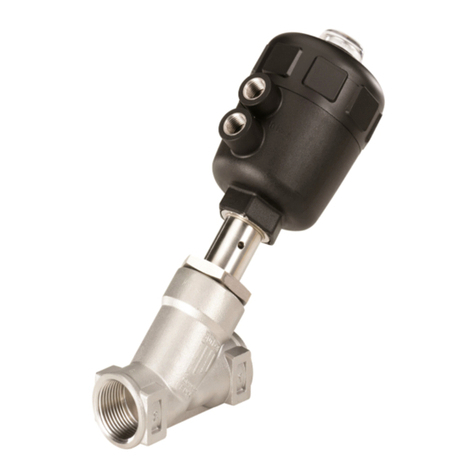
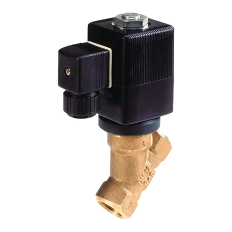
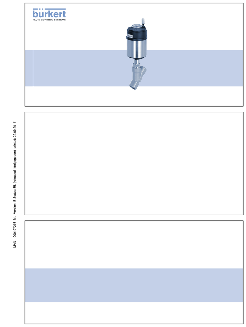
Burkert 2300 Series User manual

Operating Instructions
Bedienungsanleitung
Manuel d‘utilisation
Type 2300
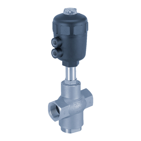
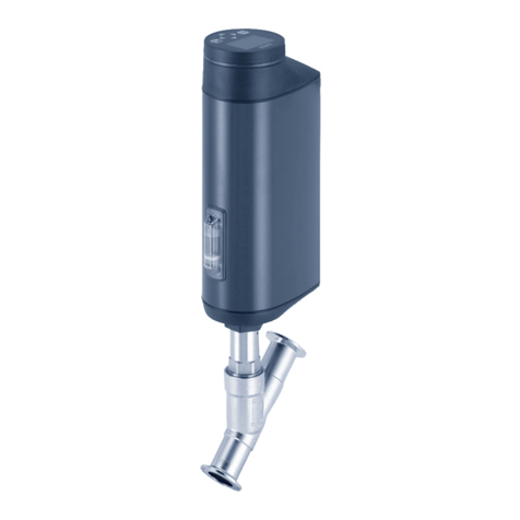
2/2-way angle-seat control valve
2/2-Wege-Schrägsitzregelventil
Vanne de réglage à siège incliné 2/2 voies

We reserve the right to make technical changes without notice.
Technische Änderungen vorbehalten.
Sous réserve de modifications techniques.
© Bürkert Werke GmbH & Co. KG, 2008 - 2018
Operating Instructions 1802/09_EU-ML_00805626 / Original DE

3
Contents
1 OPERATING INSTRUCTIONS............................................... 4
1.1 Symbols....................................................................... 4
1.2 Denitionofterm/abbreviation .................................. 4
2 INTENDED USE .................................................................... 5
3 BASIC SAFETY INSTRUCTIONS.......................................... 5
4 GENERAL INFORMATION .................................................... 7
4.1 Contactaddress.......................................................... 7
4.2 Warranty ...................................................................... 7
4.3 Informationontheinternet .......................................... 7
5 PRODUCT DESCRIPTION .................................................... 7
5.1 Generaldescription ..................................................... 7
5.2 Versions....................................................................... 7
5.3 Properties .................................................................... 8
5.4 Designatedapplicationarea........................................ 9
6 STRUCTURE AND FUNCTION ............................................. 9
6.1 Structure...................................................................... 9
6.2 Function..................................................................... 10
7 TECHNICAL DATA............................................................... 12
7.1 Conformity................................................................. 12
7.2 Standards .................................................................. 12
7.3 Typelabel .................................................................. 12
7.4 Operatingconditions ................................................. 12
7.5 Flowvaluesandcharacteristics ................................ 17
7.6 Generaltechnicaldata............................................... 21
8 INSTALLATION .................................................................... 22
8.1 Safetyinstructions..................................................... 22
8.2 Beforeinstallation...................................................... 23
8.3 Installation ................................................................. 24
8.4 Pneumaticconnection............................................... 28
8.5 Start-up ..................................................................... 29
8.6 Removal .................................................................... 29
9 ELECTRICAL CONTROL UNIT ........................................... 29
10 MAINTENANCE, CLEANING .............................................. 30
10.1 Safetyinstructions..................................................... 30
10.2 Maintenancework ..................................................... 30
10.3 Replacingthewearingparts...................................... 31
11 MALFUNCTIONS ................................................................ 40
12 REPLACEMENT PARTS...................................................... 41
12.1 Replacementpartsets .............................................. 41
12.2 Installationtools ........................................................ 43
13 PACKAGING, TRANSPORT, STORAGE ............................. 43
english
Type 2300

4
Operating instructions
CAUTION!
Warns of a possible danger!
▶Failuretoobservethiswarningmayresultinamoderately
severeorminorinjury.
NOTE!
Warns of damage to property!
▶Failuretoobservethewarningmayresultindamagetothe
deviceortheequipment.
Indicatesimportantadditionalinformation,tipsand
recommendations.
Referstoinformationintheseoperatinginstructionsorin
otherdocumentation.
▶designatesinstructionsforriskprevention.
→Designatesaprocedurewhichyoumustcarryout.
1.2 Denition of term / abbreviation
Theterm“device”usedintheseinstructionsalwaysstandsfor
theangle-seatcontrolvalveType2300.
Theabbreviation“Ex”usedintheseinstructionsalwaysstands
for“explosion-protected”.
1 OPERATING INSTRUCTIONS
Theoperatinginstructionsdescribetheentirelifecycleofthedevice.
Keep these instructions in a location which is easily accessible
toeveryuserandmaketheseinstructionsavailabletoeverynew
ownerofthedevice.
The operating instructions contain important safety information!
Failuretoobservetheseinstructionsmayresultinhazardous
situations.
▶Theoperatinginstructionsmustbereadandunderstood.
1.1 Symbols
DANGER!
Warns of an immediate danger!
▶Failuretoobservethewarningmayresultinafatalorserious
injury.
WARNING!
Warns of a potentially dangerous situation!
▶Failuretoobservethewarningmayresultinseriousinjuries
ordeath.
english
Type 2300

5
Intended use
2 INTENDED USE
Non-intended use of the angle-seat control valve Type 2300 may
be a hazard to people, nearby equipment and the environment.
▶Thedeviceisdesignedforthecontrolledowofliquidand
gaseousmedia.Operationispossibleonlyincombination
withasuitablecontrolunit.
▶Inthepotentiallyexplosion-riskareatheglobevalvetype
2300maybeusedonlyaccordingtothespecicationon
theseparateExtypelabel.Foruseobservetheadditional
informationenclosedwiththedevicetogetherwithsafety
instructionsfortheexplosion-riskarea.
▶DeviceswithoutaseparateExtypelabelmaynotbeusedin
apotentiallyexplosivearea.
▶Theadmissibledata,theoperatingconditionsandcondi-
tionsofusespeciedinthecontractdocuments,operating
instructionsandonthetypelabelaretobeobservedduring
use.Thesearedescribedinthechapterentitled“7Technical
data”.
▶Protectdevicefromdamagingenvironmentalinuences(e.g.
radiation,humidity,steam,etc.).Ifanythingisunclear,consult
therelevantsalesoce.
▶Thedevicemaybeusedonlyinconjunctionwiththird-party
devices and components recommended and authorized by
Bürkert.
▶Correcttransportation,correctstorageandinstallationand
carefuluseandmaintenanceareessentialforreliableand
faultlessoperation.
▶Usethedeviceonlyasintended.
3 BASIC SAFETY INSTRUCTIONS
Thesesafetyinstructionsdonotmakeallowanceforany
•contingenciesandeventswhichmayariseduringtheinstallation.
operationandmaintenanceofthedevices.
•localsafetyregulations;theoperatorisresponsibleforobserving
theseregulations,alsowithreferencetotheinstallationpersonnel.
DANGER!
Risk of injury from high pressure in the equipment or device!
▶Beforeworkingonequipmentordevice,switchothepres-
sureanddeaerateordrainlines.
Risk of injury from electric shock (when electrical component
installed).
▶Beforereachingintothedevice,switchothepowersupply
andsecuretopreventreactivation!
▶Observeapplicableaccidentpreventionandsafetyregulati-
onsforelectricalequipment!
english
Type 2300

6
Basic safety instructions
WARNING!
Risk of injury when opening the actuator!
Theactuatorcontainsatensionedspring.Iftheactuatoris
opened,thereisariskofinjuryfromthespringjumpingout!
▶Theactuatormustnotbeopened.
Risk of injury from moving parts in the device!
▶Donotreachintoopenings.
Danger due to loud noises.
▶Dependingontheoperatingconditions,thedevicemaygenerate
loudnoises.Moredetailedinformationonthelikelihoodofloud
noisesisavailablefromtherelevantsalesoce.
▶Wearhearingprotectionwheninthevicinityofthedevice.
CAUTION!
Risk of burns!
Thesurfaceofthedevicemaybecomehotduringlong-term
operation.
▶Donottouchthedevicewithbarehands.
Leaking medium when the packing gland is worn.
▶Regularlycheckreliefboreforleakingmedium.
▶Ifthemediaishazardous,protecttheareasurroundingthedis-
chargepointagainstdangers.
General hazardous situations.
Topreventinjury,ensurethat:
▶Thatthesystemcannotbeactivatedunintentionally.
▶Installationandrepairworkmaybecarriedoutbyauthorized
techniciansonlyandwiththeappropriatetools.
▶Afteraninterruptioninthepowersupplyorpneumatic
supply,ensurethattheprocessisrestartedinadenedor
controlledmanner.
▶Thedevicemaybeoperatedonlywheninperfectcondition
andinconsiderationoftheoperatinginstructions.
▶Observethesafetyregulationsspecictotheplantforapplica-
tionplanningandoperationofthedevice.
▶Theplantoperatorisresponsibleforthesafeoperationandhan-
dlingoftheplant.
▶Thegeneralrulesoftechnologyapplytoapplicationplanning
andoperationofthedevice.
To prevent damage to property of the device, ensure:
▶Supplythemediaconnectionsonlywiththosemediawhichare
speciedasowmediainthechapterentitled“7Technicaldata”.
▶Donotputanyloadsonthevalve(e.g.byplacingobjectson
itorstandingonit).
▶Donotmakeanyexternalmodicationstothevalves.Donot
paintthebodypartsorscrews.
▶Donottransport,installorremoveheavydeviceswithouttheaid
ofasecondpersonandusingsuitableauxiliaryequipment.
▶The exhaust air may be contaminated with lubricants in the
actuator.
english
Type 2300

7
General information
4 GENERAL INFORMATION
4.1 Contact address
Germany
BürkertFluidControlSystem
SalesCentre
Christian-Bürkert-Str.13-17
D-74653Ingelngen
Tel.+49(0)7940-1091111
Fax+49(0)7940-1091448
E-mail:[email protected]
International
Contactaddressesarefoundonthenalpagesoftheprinted
operatingmanual.
YoucanalsondinformationontheInternetunder:
www.burkert.com
4.2 Warranty
Thewarranty is onlyvalidif the device is usedasauthorized in
accordancewiththespeciedapplicationconditions.
4.3 Information on the internet
TheoperatinginstructionsanddatasheetsforType2300canbe
foundontheInternetat:www.burkert.com
5 PRODUCT DESCRIPTION
5.1 General description
The2/2-wayangle-seatcontrolvalveType2300issuitablefor
liquidandgaseousmedia.
Itusesneutralgasesorair(controlmedia)tocontroltheow
ofwater,alcohol,oil,fuel,hydraulicuid,salinesolution,lye,
organicsolventandsteam(owmedia).
Theoperationoftheangle-seatcontrolvalveType2300ispos-
sibleonlyincombinationwithancontrolunit.Possiblecontrol
unitsare:
PositionerType8692,8694and8696
ProcesscontrollerType8693
5.2 Versions
Thereare2versionsoftheangle-seatcontrolvalveType2300.
•Standardversion–withoutseparateExtypelabel.
Thestandardversionmustnotbeusedinthepotentially
explosivearea.
•Exversion–withseparateExtypelabel.
TheExversionmaybeusedinthepotentiallyexplosivearea.
Indoingso,observethespecicationsontheseparateExtype
labelandtheadditionalinformationenclosedwiththedevice
togetherwithsafetyinstructionsfortheExarea.
english
Type 2300

8
Product description
5.3 Properties
•DirectinstallationofthepositionersType8692/8694/8696or
theprocesscontrollerType8693.
•Hightightnessbyself-adjustingpackingglands(spindle
sealingelement).
•ClosestightlywhenusingthePTFEcontrolcone.
•Highowvaluesbythestreamlinedvalvebodymadeof
stainlesssteel.
•Simpleandfastreplacementofthecontrolcone.
•Actuatorcanberotatedsteplesslythrough360°.
•Maintenance-freeundernormalconditions.
5.3.1 Technical features
•Characteristic:modiedequal-percentageowcharacteristic.
•Theoreticalsettingratio(KvS /Kv0)50:1;alternatively,other
settingratioscanberealized.
•KvRvalue,i.e.thesmallestKvvalueatwhichtheangularity
toleranceaccordingtoDINIEC534-2-4isstillmaintained:
≤DN20 KvRat10%ofthestroke
>DN20 KvRat5%ofthestroke
5.3.2 Options
Controlunit:Dependingontherequirement,controlunitsin
variousdesignsareavailable.
•PositionerType8692,8694and8696
•ProcesscontrollerType8693
•Vacuum
•FoodconformityFDA
•DVGW
•ATEX
5.3.3 Device versions
Pilot pressure
Designswithlowerpilotpressure(reducedspringforce)are
availableonrequest.
ContactyourBürkertsalesoceorourSalesCentre.
E-mail:[email protected]
Actuator sizes
Dependingontheorice,theangle-seatcontrolvalveisavailable
forthefollowingactuatorsizes:
Orice DN Available actuator size ø [mm]
15 50 70 -
-
20 50 70
25 50 70 90
32
-
70 90
40
-
90 130
50 90 130
65 -130
Tab. 1: Actuator sizes
english
Type 2300

9
Structure and function
5.4 Designated application area
Observethemaximumpressurerangeaccordingtothe
typelabel!
•Neutralgasesandliquidsupto16bar.
•Steamupto11barabsolute/185°Cforseatsealsteel/steel.
Steamupto2.7barabsolute/130°CforseatsealPTFE/
steel.
•Aggressivemedia.
5.4.1 Application areas
e.g. Plantconstruction
Foodprocessing
Chemicalengineering
Sterilizerconstruction,temperaturecontrol
Gasdosing
Conveyorsystemsforvariousbulkmaterial(alsosen-
sitivefoodstu)
6 STRUCTURE AND FUNCTION
Theoperationoftheangle-seatcontrolvalveType2300
ispossibleonlyincombinationwithacontrolunit.
Possiblecontrolunitsare:
PositionerType8692,8694and8696
ProcesscontrollerType8693
6.1 Structure
Theangle-seatcontrolvalveconsistsofapneumatically
operatedpistonactuator,acontrolconeanda2/2-wayangle-
seatbody.
Viaadowelpin,thecontrolconeismodularlycoupledtothe
actuatorspindleforquickchangeovers.
Forthebody,almostanylineconnectionsarepossible.
Athreadedportandaweldedendareoeredasastandard
version.
Thevalveseatsareincorporateddirectly.Theowinletisalways
underseat.
Thedescriptionofthecontrolfunction(CF)canbefound
inchapterentitled“6.2.1Controlfunctions(CF)”.
english
Type 2300

10
Structure and function
Actuatorcover
Actuatorbody
Interfaceactuator/bodywithwrench
at
Angle-seatbody
Numbersforindicatingthedirection
ofow
Portconnection
ExhaustairportforCFA,CFB
PilotairportforCFI
PilotairportforCFA,CFB,CFI
2
1
Fig. 1: Angle-seat control valve Type 2300, structure and
description
6.2 Function
Theseatofthevalveisalwaysclosedagainstthemediumow.
Springforce(CFA)orpneumaticpilotpressure(CFBandCFI)
generatestheclosingforceonthecontrolcone.Theforceis
transferredviaaspindlewhichisconnectedtotheactuator
piston.
6.2.1 Control functions (CF)
WARNING!
For control function I – Danger if pilot pressure fails!
ForcontrolfunctionIcontrolandresettingoccurpneumatically.
Ifthepressurefails,nodenedpositionisreached.
▶Toensureacontrolledrestart,rstpressurizethedevicewith
pilotpressure,thenswitchonthemedium.
Control function A (CFA)
Normallyclosedbyspringaction.
english
Type 2300

11
Structure and function
Control function B (CFB)
Normallyopenbyspringaction.
Control function I (CFI)
Actuatingfunctionviareciprocal
pressurization.
6.2.2 Flow direction below the seat
Dependingontheversion,thevalveisclosedagainstthe
mediumowwithspringforce(controlfunctionA,CFA)orwith
pilotpressure(controlfunctionBorI,CFBorCFI).
Asthemediumpressureisunderthecontrolcone,thispressure
contributestotheopeningofthevalve.
WARNING!
Medium may be discharged if minimum pilot pressure is too
low or medium pressure too high!
IftheminimumpilotpressureistoolowforCFBandCFIorthe
permittedmediumpressureisexceeded,leaksmayoccur.
▶Observeminimumpilotpressure.
▶Donotexceedmediumpressure.
▶Seechapterentitled“7.4.3Pressureranges”.
Rest
position
CFA
Rest
position
CFB/CFI
Fig. 2: Flow direction below the seat
(Rest open/closed, closing against medium)
english
Type 2300

12
Technical data
7 TECHNICAL DATA
7.1 Conformity
Type2300conformswiththeEUDirectivesaccordingtotheEU
DeclarationofConformity.
7.2 Standards
Theappliedstandards,whichverifyconformitywiththeEU
Directives,canbefoundontheEU-TypeExaminationCerticate
and/ortheEUDeclarationofConformity.
AccordingtoPressureEquipmentDirectivethefollowingoperating
conditionsmustbeobserved:
Lineconnection
orice
Maximumpressureforcompressibleuids
ofGroup1(hazardousgasesandvapors
accordingtoArt.3No.1.3Letterarst
dash)
DN65 15bar
7.3 Type label
00285864
2300 A 25M PTFE VA
Tmed -10°C - +130°C
Flow 1 2
Pilot 5,5 - 7bar
Pmed 12bar W1XMS
CE
G1 Kvs16
CEidentication
Permittedpilot
pressure
Permittedmedium
pressure
Type
Controlfunction
(CF)
Oriceofthebody/
actuatorsize
Sealingmaterial1) Bodymaterial1)
Identication
numberofthe
device
Flowdirection
Permittedmedium
temperature
Dateof
manufacture
Maindimensions
oflineconnection
Flowcapacityinstandard
productionconditions
1) For description of versions see “7.6 General technical data”
7.4 Operating conditions
Observepermittedrangesonthetypelabelofthe
device!
english
Type 2300

13
Technical data
7.4.1 Temperature ranges
Actuator
size
[mm]
Actuator
material
Medium Environ-ment
2)
Seat seal
steel / steel
Seat seal
PTFE / steel
ø 50
PPS -10...+185°C -10...+130°C
-10...+60°C3)
-10...+100°C4)
ø 70
ø 90
ø 130
Tab. 2: Temperature ranges
2)
If a pilot valve/control unit is used, the max. ambient
temperature is +55 °C.
Theangle-seatcontrolvalveissuitableforsteam
sterilization.
3) Pilot air ports with push-in connector
4) Pilot air ports with threaded bushing.
7.4.2 Control medium
Inconjunctionwithpneumaticcontrolunits(positioneror
processcontrollers),pilotairaccordingtoDINISO8573-1must
beused:
•Class3(forwatercontent)
•Class5(fordustandoilcontent).
Thespecicationisdescribedindetailintheoperating
instructionsoftherespectivepositioner/processcon-
trollerinthechapterentitled“Technicaldata”.
7.4.3 Pressure ranges
Pilot pressure range5) on controlled operation
Actuator
size
Orice DN
[mm]
Pilot pressure range5) [bar]
CFA CFB
ø 50 mm 15–25 3.4–5.5 3.3–5.1
ø 70 mm 15–32 2.6–5.5 2.6–5.2
ø 90 mm 25–50 3.3–5.5 1.8–2.5
ø 130 mm 40–50 3.3–5.6 1.9–2.7
65 4.6–5.6 1.9–2.7
Tab. 3: Pilot pressure range on controlled operation
5) To ensure reliable operation with pneumatic control
units (positioner or process controller), observe the
permitted minimum and maximum pilot pressure!
english
Type 2300

14
Technical data
Maximum pilot pressure for valves
without pneumatic control unit
Actuator size Actuator material max. permitted pilot
pressure6)
ø 50 mm
PPS 10barø 70 mm
ø 90 mm
ø 130 mm 7bar
Tab. 4: Pilot pressure for valves without pneumatic control unit
6) Observe the maximum pressure range according to
the type label!
Operating pressure for control function A7)
Actuator size Orice DN
[mm]
Required pilot
pressure [bar]
Max. sealed
medium
pressure [bar]
ø 50 mm
15 5.5 16
20 5.5 10
25 5.5 5
ø 70 mm
15 5.5 16
20 5.5 16
25 5.5 12
32 5.5 6
ø 90 mm
25 5.5 16
32 5.5 16
40 5.5 12
50 5.5 7
ø 130 mm
40 5.5 16
50 5.5 16
65 5.6 16(15*)
Tab. 5: Operating pressure for control function A
*According to Pressure Equipment Directive for compressible uids of Group
1 (hazardous gases and vapors according to Art. 3 No. 1.3 Letter a rst dash)
7) The description of the control function (CF) can be found in
chapter entitled “6.2.1 Control functions (CF)”.
english
Type 2300

15
Technical data
Pilot pressure for control function B8)
Actuator
size
Orice DN
[mm]
Pilot pressure[bar] Max. per-
mitted medium
pressure [bar]
for medium pressure
0 bar max
ø 50 mm
15 4.6 6.6 16
20 5.1 7.0 9
25 5.1 7.0 5
ø 70 mm
15 4.4 5.3 16
20 5.2 6.8 16
25 5.2 7.0 12
32 5.2 7.0 6
ø 90 mm
25 2.4 4.2 16
32 2.4 5.3 16
40 2.5 6.5 16
50 2.5 7.0 14
ø 130 mm
40 2.7 4.5 16
50 2.7 5.6 16
65 2.7 7.0 16(15*)
Tab. 6: Pilot pressure for control function B
*According to Pressure Equipment Directive for compressible uids of Group
1 (hazardous gases and vapors according to Art. 3 No. 1.3 Letter a rst dash)
Designswithlowerpilotpressure(reducedspringforce)
areavailableonrequest.
8) The description of the control function (CF) can be found in
chapter entitled “6.2.1 Control functions (CF)”.
Required minimum pilot pressure depending on medium
pressure for circuit function B
DN20
DN25
0
2
4
6
8
10
12
14
16
012345678910
DN1
5
Pilot pressure [bar]
Medium pressure [bar]
ø 50 CFB
Fig. 3: Pressure graph, actuator ø 50 mm, control function B
english
Type 2300

16
Technical data
DN2
0
DN25
0
2
4
6
8
10
12
14
16
012345678910
DN15
DN32
Pilot pressure [bar]
Medium pressure [bar]
ø 70 CFB
Fig. 4: Pressure graph, actuator ø 70 mm, control function B
DN3
2
DN50
0
2
4
6
8
10
12
14
16
012345678910
DN2
5
DN4
0
Pilot pressure [bar]
Medium pressure [bar]
ø 90 CFB
Fig. 5: Pressure graph, actuator ø 90 mm, control function B
DN4
0
0
2
4
6
8
10
12
14
16
012345678910
DN50
DN65
Pilot pressure [bar]
Medium pressure [bar]
ø 130 CFB
Fig. 6: Pressure graph, actuator ø 130 mm, control function B
english
Type 2300

17
Technical data
7.5 Flow values and characteristics
Flow values for DN15
Stroke
[%] Kv value [m3/h] Stroke
[%] Kv value [m3/h]
50.16 60 3.5
10 0.17 70 4.0
20 0.22 80 4.5
30 0.4 90 4.8
40 1.2 100 5.0
50 2.7
Tab. 7: Flow values for DN15
Flow characteristics for DN15
Stroke [%]
Kv [m3/h]
0,0
5,0
4,5
4,0
3,5
3,0
2,5
2,0
1,5
1,0
0,5
020
40 60 80
100
Fig. 7: Flow characteristics for DN15
Flow values for DN20
Stroke
[%] Kv value [m3/h] Stroke
[%] Kv value [m3/h]
50.26 60 7.2
10 0.27 70 8.3
20 0.4 80 9.1
30 1.1 90 9.6
40 4.0 100 10.0
50 5.9
Tab. 8: Flow values for DN20
Flow characteristics for DN20
Stroke [%]
Kv [m3/h]
0,0
10,0
9,0
8,0
7,0
6,0
5,0
4,0
3,0
2,0
1,0
020 40 60 80 100
Fig. 8: Flow characteristics for DN20
english
Type 2300

18
Technical data
Flow values for DN25
Stroke
[%] Kv value [m3/h] Stroke
[%] Kv value [m3/h]
50.34 60 11.5
10 0.36 70 13.0
20 0.62 80 14.2
30 1.5 90 15.4
40 5.2 100 16.0
50 8.9
Tab. 9: Flow values for DN25
Flow characteristics for DN25
Stroke [%]
Kv [m3/h]
0
14
12
10
8
6
4
2
020 40 60 80 100
16
Fig. 9: Flow characteristics for DN25
Flow values for DN32
Stroke
[%] Kv value [m3/h] Stroke
[%] Kv value [m3/h]
50.43 60 13.8
10 0.52 70 16.4
20 0.82 80 19.2
30 1.4 90 21.3
40 4.0 100 23.0
50 9.3
Tab. 10: Flow values for DN32
Flow characteristics for DN32
Stroke [%]
Kv [m3/h]
0
20
18
16
14
12
10
8
6
4
2
020 40 60 80 100
22
24
Fig. 10: Flow characteristics for DN32
english
Type 2300

19
Technical data
Flow values for DN40 - Actuator size ø90
Stroke
[%] Kv value [m3/h] Stroke
[%] Kv value [m3/h]
50.47 60 21.5
10 0.62 70 25.3
20 1.1 80 28.8
30 2.6 90 31.6
40 10.0 100 34.0
50 17.0
Tab. 11: Flow values for DN40 - Actuator size ø90
Flow characteristics for DN40 - Actuator size ø90
Stroke [%]
Kv [m3/h]
0
35
30
25
20
15
10
5
020 40 60 80 100
Fig. 11: Flow characteristics for DN40 - Actuator size ø90
Flow values for DN40 - Actuator size ø130
Stroke
[%] Kv value [m3/h] Stroke
[%] Kv value [m3/h]
50.48 60 24.3
10 0.66 70 28.3
20 1.4 80 31.7
30 5.1 90 34.5
40 14.0 100 36.0
50 20.0
Tab. 12: Flow values for DN40 - Actuator size ø130
Flow characteristics for DN40 - Actuator size ø 130
Stroke [%]
Kv [m3/h]
0
35
30
25
20
15
10
5
020 40 60 80 100
40
Fig. 12: Flow characteristics for DN40 - Actuator size ø130
english
Type 2300

20
Technical data
Flow values for DN50 - Actuator size ø90
Stroke
[%] Kv value [m3/h] Stroke
[%] Kv value [m3/h]
50.85 60 28.6
10 1.1 70 35.6
20 1.6 80 40.6
30 2.7 90 45.0
40 10.2 100 49.0
50 20.0
Tab. 13: Flow values for DN50 - Actuator size ø90
Flow characteristics for DN50 - Actuator size ø90
Stroke [%]
Kv [m3/h]
0
50
45
40
35
30
25
20
15
10
5
020
40 60 80
100
Fig. 13: Flow characteristics for DN50 - Actuator size ø90
Flow values for DN50 - Actuator size ø130
Stroke
[%] Kv value [m3/h] Stroke
[%] Kv value [m3/h]
50.87 60 35.0
10 1.2 70 40.3
20 1.8 80 45.0
30 4.0 90 48.0
40 15.2 100 53.0
50 26.0
Tab. 14: Flow values for DN50 - Actuator size ø130
Flow characteristics for DN50 - Actuator size ø 130
Stroke [%]
Kv [m3/h]
00
20
40 60 80
100
20
5
10
15
25
30
35
40
45
50
55
Fig. 14: Flow characteristics for DN50 - Actuator size ø130
english
Type 2300
Other manuals for 2300 Series
6
Table of contents
Other Burkert Control Unit manuals

Burkert
Burkert 2106 User manual

Burkert
Burkert 6240 User manual

Burkert
Burkert 6517 User manual

Burkert
Burkert 6228 User manual

Burkert
Burkert 2030 User manual

Burkert
Burkert 0280 User manual

Burkert
Burkert 8647 AirLINE SP User manual

Burkert
Burkert 8640 User manual

Burkert
Burkert 2712 Series User manual

Burkert
Burkert 0142 User manual

Burkert
Burkert 2100 series User manual

Burkert
Burkert 2006 User manual

Burkert
Burkert 1066 User manual

Burkert
Burkert 2012 User manual

Burkert
Burkert 2933 User manual

Burkert
Burkert 8695 User manual

Burkert
Burkert 2101 User manual

Burkert
Burkert 0470 User manual

Burkert
Burkert 0124 User manual

Burkert
Burkert Type 2000 User manual